© 2016, IRJET | Impact Factor value: 4.45 | ISO 9001:2008 Certified Journal | Page 757
Effect of grit blasting and intermediate layer of MoSi
2on Life time of
thermal barrier coating
Mujeebulla Khan Guttal
1*, Dr.Abdul Sharief
21stjit, Ranebennur, Karbataka, India.
2P A College of Engineering Mangalore, Karnataka, India
*Mujeebulla khan Guttal, [email protected]
Abstract-
A set of specimens prepared with Thermal barrier coatings (TBC) by air plasma sprayed containing substrate Haynes 230 and bond coat NiCrAlY with top coat as 7 wt% Y2O3 stabilized ZrO2.Conventional thermal barrier coating containing top coating and bond coating. The present developed system introduces a protective intermediate layer on bond coat of MoSi2 for preventing oxidation along with substrate treated with grit blasting. The samples treated with thermal cycling to cause failure. The present work reveals the effect of surface roughness along with intermediate layer on thermal fatigue life of TBC. High interface roughness wasfound to promote longer fatigue lives along with intermediate layer oxidizes to prevent bond coat oxidation.Key words:TBC, Mosi2, ASP, YSZ, NiCrAlY
1. Introduction
–Gas turbines performance mainly depends on the temperature [4], an increase in efficiency can achieved
by increasing combustion temperature [5 –9]. A higher turbine entry temperature (TET) results in higher efficiency. Consequently, development of gas turbines has driven the service temperature to higher and higher level.
Thermal barrier coating (TBC) containing ceramic top coat(TC)which acts as resistant to heat, and bond coat(BC) to improve adhesion of top coat along with metallic substrate[10]. During operation thermal loads arise from the difference coefficient of thermal expansion (CTE) of the ceramic top coat (TC) and the metallic bond coat (BC). Failure occurs at interface of BC/TC because of thermally grown oxides (TGO).There are different ways that a TBC can fail, but growth of the TGO layer at the TC and BC interface plays a significant role in failure[11].
Bond coat oxidation can be reduced by following methods
(1) Lowering interface temperature-A simple way to decrease interface temperature is to apply a thicker top coat[12]. However, the thermal stresses in the top coat are then higher and in some cases the top coat delaminates even during the spraying process [13,14].
(2) Including an oxygen diffusion barrier between the top coat and the bond coat- A layer which is introduced to prevent the oxidation of BC.
© 2016, IRJET | Impact Factor value: 4.45 | ISO 9001:2008 Certified Journal | Page 758 2. Experiment
2.1 Materials
Four TBC coated specimens one with conventional two layer coating and other one having 3 layer along with intermediate layer substrate treated with grit blasting put through thermal cycling until failure. The sample substrates cut from 5 mm thick Haynes 230 sheet material in 30x50 mm rectangles. The substrates coated by 150μm of NiCrAlY deposited, and 250μm of 7%-yattria partially-stabilized zirconia deposited by atmospheric plasma spraying (APS).
2.2 Coating preparation
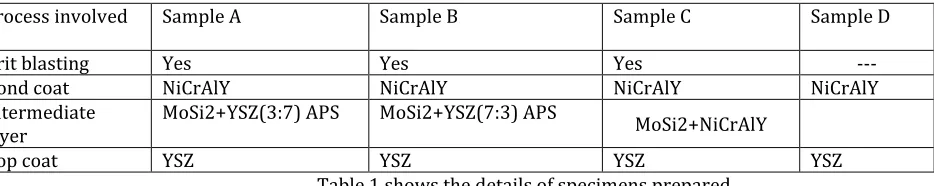
The roughness on substrate accomplished by grit blasting.Samples were grit-blasted by corundum with a grain size of 60-mesh to roughen and clean the substrate surface to achieve the required roughness for coating adhesion. The bond coat NiCrAlY deposited on the grit blasted roughened surface using APS with 150µm, then MoSi2 intermediate layer was deposited on the bond coating surface, and then the top YSZ coating sprayed on the MoSi2 surface. A blended composite powder of MoSi2and YSZ used at weight ratio of 3:7 for sample A 7:3 for sample B. All the coatingswere deposited using APS.Table 1 shows the details of specimens prepared
Process involved Sample A Sample B Sample C Sample D
Grit blasting Yes Yes Yes ---
Bond coat NiCrAlY NiCrAlY NiCrAlY NiCrAlY
Intermediate
layer MoSi2+YSZ(3:7) APS MoSi2+YSZ(7:3) APS MoSi2+NiCrAlY
[image:2.612.44.511.329.422.2]Top coat YSZ YSZ YSZ YSZ
Table 1 shows the details of specimens prepared
MoSi2shows the self-repair characteristic through formation of SiO2 during oxidation of MoSi2. The self-repair characteristic tested. NiCrAlY sprayed as the bond coating on the substrates APS. A composite coating of MoSi2 and NiCrAlY was then applied by APS using a different powder mixture of MoSi2 and NiCrAlY.Typical microphotographs of coatings A, B, C, and D shown in Fig.1.
Sample A
Sample B
Sample C
Sample D
[image:2.612.10.553.528.664.2]© 2016, IRJET | Impact Factor value: 4.45 | ISO 9001:2008 Certified Journal | Page 759 2.3 Thermal cyclic test
The samples were thermally cycled in a furnace until failure. One thermal cycle includes heating to 1100 °C for 1 hour and cooling by forced airflow to reach up to 1000 C which reached in about 10 min of cooling. After failure, this considered to occur when more than 25 % of the top coat had spalled.
2.4 Roughness generated on BC by grit blasting
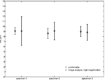
[image:3.612.134.471.279.538.2]Roughness of BC plays a vital role in fatigue life of TBC system because the roughness increases adhesion strength. The roughness generated by grit blasting measured by using cross sectioned specimen. The roughnesses measured by image analysis and compared with the profilometer. The test conducted to a sample length 800µm and the compared results shown in Figure 2
Figure 2. Comparison between the results from a profilometer and results obtained by image analysis.
3. Results
3.1 Influence of roughness generated by grit blasting
© 2016, IRJET | Impact Factor value: 4.45 | ISO 9001:2008 Certified Journal | Page 760 Figure.3 The influence of Ra and Rc on the thermal fatigue life
From the figure it observed that the Specimens A B and C with grit blasting observed to give much longer fatigue life because of the roughness produced in comparison with the specimen D without grit blasted specimen.
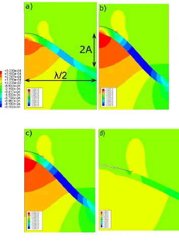
3.2 FE crack modeling
The FE analysis done on least representative cell of TBC. Figure 4 shows the models generated using FE code abacus. It assumed to have least representative cell on left boundary, and right kinetic boundary conditions applied. The crack growth developed for both in TGO/TC and BC/TGO interface.
© 2016, IRJET | Impact Factor value: 4.45 | ISO 9001:2008 Certified Journal | Page 761
[image:5.612.45.399.97.572.2]
© 2016, IRJET | Impact Factor value: 4.45 | ISO 9001:2008 Certified Journal | Page 762 Figure 5. The calculated energy release rate G for a) BC/TGO crack, and b) TGO/TC crack.
3.3 Role of Intermediate layer
MoSi2 exhibits the characteristic of self-repair through formation of SiO2 during oxidation of MoSi2. Preparation methods of the intermediate layer significantly influence durability of the triple layered TBCs. Specimens prepared with APS forms Mo5Si3 through oxidation of MoSi2 during spraying according to following reaction.
© 2016, IRJET | Impact Factor value: 4.45 | ISO 9001:2008 Certified Journal | Page 763 The cracks and pores formed in the intermediate layer during the thermal cyclic test sealed by a protective SiO2 coating and oxidation of the NiCrAlY bond coating prevented. The self-repair mechanism of intermediate layer is schematically shown in Fig.6. Case I presents the morphology of the cracks initiated at the parallel direction to the interface between the bond coating and the intermediate layer[9]. Case II presents propagation of existing longitudinal
cracks to the intermediate layer under the tensile stress which induced by the thermal cycle
.
[image:7.612.77.534.194.470.2]Fig. 6 Schematic diagrams of proposed self-repair mechanism of sprayed coatings for the cases I and II.
4. Discussions
It has observed that large variation in fatigue life caused by interface roughness generated by grit blasting and FE models shows the crack growth in TBCs. The performed modeling with FE may serve as a tool for evaluation of the relative behavior of crack growth in the suggested interface models.
In conventional double layer TBC oxygen atoms from the atmosphere penetrate TC mainly through cracks and pores to the bond coating and oxidize the BC that is NiCrAlY at high temperatures. as a result TGO formed at interface of TC/BC. The intermediate layer of MoSi2 used to form triple layer of TBC causes reduction in growth of TGO by filling the pores and cracks.
5. Conclusion
© 2016, IRJET | Impact Factor value: 4.45 | ISO 9001:2008 Certified Journal | Page 764 roughened surface. Profilimeter and image analysis used to find the various roughness parameters like Ra and Rc. It was found to have correlation with thermal fatigue life where higher values of roughness Ra and Rc gives longer life. These roughness parameters are applied to FE modeling of crack growth in specimens for shortest and longer life.
MoSi2 composite has introduced as an intermediate layer to the conventional duplex TBC systems to create a triple layered TBCs to prevent the oxidation of MCrAlY bond coating and improve the thermal cyclic performance. Specimen C with MoSi2 and NiCrAlY as intermediate layer was found to give longer thermal fatigue life of TBC. MoSi2 composite of intermediate layer of C forms SiO2 after oxidation. The formed SiO2 seals the pores and cracks and prevents oxidation of bond coat which reduces the formation TGO thereby increasing the thermal fatigue life of TBC.
REFERENCES
1) S. Sjostrom, H. Brodin, Thermomechanical fatigue life of TBCs - experimental and modelling aspects, Ceram. Eng.
Sci. Proc. 31 (2010) 23–39
2) Dong Liu • Peter E. J. Flewitt • Keith R. Hall, Residual Stress Evolution and Failure Modes in a Thermal Barrier
Coating Deposited on a Curved Substrate. Oxid Met (2014) 81:69–82
3) Baig M, Khalid F, Khan F, et al. Properties and residual stress distribution of plasma sprayed magnesia stabilized
zirconia thermal barrier coatings. Ceram Int, 2014, 40: 4853–4868
4) Wu L F, Zhu J G, Xie H M. Numerical and experimental investigation of residual stress in thermal barrier coatings
during APS process. J Therm Spray Technol, 2014, 23: 653–665
5) ZHU JianGuo1, CHEN Wei2 & XIE HuiMin3 Simulation of residual stresses and their effects on thermal barrier coating systems using finite element method. Sci China-Phys Mech Astron March (2015) Vol. 58 No. 3
6) K. Ito, H. Kuriki, and M. Enoki, A Numerical Study on Generation Mechanism of Vertical Cracks in Top Coat of
TBCs During APS Deposition, J.of Thermal Spray Techno, 17 March 2015
7) K. Ito, H. Kuriki, H. Araki, S. Kuroda, and M. Enoki, Detection of Segmentation Cracks in Top Coat of Thermal Barrier Coatings During Plasma Spraying by On-Contact Acoustic Emission Method, Sci. Technol. Adv. Mater., 2014, 15, p 035007
8) Jie Cai, Qingfeng Guan, Peng Lv, Xiuli Hou, Zhiping Wang, and Zhiyong Han, Adhesion Strength of Thermal
Barrier Coatings with Thermal-Sprayed Bondcoat Treated by Compound Method of High-Current Pulsed Electron Beam and Grit Blasting, J Thermal Spray Technol, 17 Aril 2015
9) A.C. Karaoglanli, H. Dikici, and Y. Kucuk, Effects of Heat Treatment on Adhesion Strength of Thermal Barrier Coating Systems, Eng. Fail. Anal., 2013, 32, p 16-22
10)N. Zacchetti: Proc. ITSC (1992) 865-870
11)
H. Brodin, R. Eriksson, S. Johansson, S. Sjostrom, Fracture mechanical modelling of a plasma sprayed TBC system,Ceram. Eng. Sci. Proc. 30 (2010) 113–124
.
12)A. Casu, J. Marques, R. Valien, D. Stover, Numerical simulation of crack growth mechanisms occurring near the
© 2016, IRJET | Impact Factor value: 4.45 | ISO 9001:2008 Certified Journal | Page 765
13)
H. Brodin, R. Eriksson, S. Johansson, S. Sjöström, in: D. Zhu, H.-T. Lin, D. Singh, J. Salem (Eds.), Advanced CeramicCoatings and Interfaces IV, Ceramic Engineering and Science Proceedings, John Wiley & Sons, Inc., Hoboken, NJ,
USA, 2010
.
14)S. Sjöström, H. Brodin, in: D. Zhu, H.-T. Lin, S. Mathur, T. Ohji (Eds.), Advanced Ceramic Coatings and Interfaces V,
volume 31 of Ceramic Engineering and Science Proceedings, John Wiley & Sons, Inc., Hoboken, NJ, USA, 2010.
15)K. Ma, J. Schoenung, Surf. Coat. Technol. 205 (2010) 2273.
16)M. Di Ferdinando, A. Fossati, A. Lavacchi, U. Bardi, F. Borgioli, C. Borri, C. Giolli, A. Scrivani, Surf. Coat. Technol.
204 (15) (2010) 2499.
17)R. Eriksson, Thermal Barrier Coatings — Durability Assessment and Life Prediction,(Ph.D. thesis) Linköping
University, 2013.
18)K. Yuan, R. Eriksson, R. Lin Peng, X.-H. Li, S. Johansson, Y.-D. Wang, Mcraly coating design based on oxidation–
diffusion modelling. Part I: microstructural evolution, Surf. Coat. Technol. (2014).
19)S.Z. Hao, L.M. Zhao, D.Y. He, Nucl. Inst. Methods Phys. Res. B 312 (2013) 97–103.
20)S.Z. Hao, Y. Zhang, Y. Xu, N. Gey, T. Grosdidier, C. Dong, Appl. Surf. Sci. 285 (2013) 552–556.
21)X.X. Mei, J.Q. Fu, X.N. Li, W.F. Sun, C. Dong, Y.N. Wang, Appl. Surf. Sci. 258 (2012) 8061–8064.
22)
R. Ghasemi, R. Shoja-Razavi, R. Mozafarinia, H. Jamali, Ceram. Int. 39 (2013) 9483–9490.
23)M. Ranjbar-Far, J. Absi, G. Mariaux, D.S. Smith, Mater. Des. 32 (2011) 4961–4969.
24)
K. Bobzin,N. Bagcivan, T. Brogelmann, B. Yildrim, Surf. Coat. Technol. 237 (2013) 56–64.
25)M.H. Vidal-Sétif, C. Rio, D. Boivin, O. Lavigne, Surf. Coat. Technol. 239 (2014) 41–48.
26)G. Pujol, F. Ansart, J.-P. Bonino, A. Malié, S. Hamadi, Surf. Coat. Technol. 237 (2013)
© 2016, IRJET | Impact Factor value: 4.45 | ISO 9001:2008 Certified Journal | Page 766
Author Bibliography
Mujeebulla Khan Guttal
Is a research scholar conducting analysis on ‘Thermal stresses in composite materials’.
Presently working as assistant Professor in S.T.J.Institute of Technology. Ranebennur
Dr. Abdul Shareif