International Journal of Emerging Technology and Advanced Engineering
Website: www.ijetae.com (ISSN 2250-2459, Volume 2, Issue 9, September 2012)70
Image enhancement using Moving window-based double Haar
wavelet transform
G.venkateswarlu
1B. Jayanth nadh
2B.Hymavathi
31Pursuing M.Tech (DECS),2Assistant Professor Dept. of ECE ,SBIT, Khammam, India 3Matlab developer, nexxoft Infotel Ltd, Hyderabad, India
Abstract -In the image processing scenario the image enhancement takes high importance .Among so many image enhancement techniques the image enhancement is one of the main way. Visual information transmitted in the form of digital images is becoming a major method of communication in the modern age, but the image obtained after transmission is often corrupted with noise. The received image needs processing before it can be used in applications. Image enhancement involves the manipulation of the image data to produce a visually high quality image. Different noise models including additive and multiplicative types are used. They include Gaussian noise, Salt and Pepper noise, Speckle noise and Brownian noise. But wavelet transform considered to be better when compared with traditional techniques like median filtering etc.The proposed Double Haar Wavelet transform can make the image enhancement more effectively because of its improved low pass filter. Here, we propose an improved way in the choice of moving windows which can realize protecting the details and smoothing the noise. The estimate error of the wavelet coefficient for a pixel does not influence the estimates of the other pixels in the image. This technique can be used in the weather forecasting applications, for cleaning satellite images, in photo studios and in internet applications, etc, where the images are affected by Gaussian noise.
Keywords - DWT,Haar,Gaussian noise, Speckle noise, moving window
I. INTRODUCTION
The Images acquired through modern sensors may be contaminated by a variety of noise sources. We will assume that we are dealing with images formed from light using modern electro-optics. In particular we will assume the use of modern, charge-coupled device (CCD) cameras[1][3]
The various noise models like additive noise and multiplicative noise can be possible. They include Gaussian noise, Salt and Pepper noise, Speckle noise and Brownian noise Image addition also finds applications in mage morphing. By image multiplication, we mean the brightness of the image is varied.
There are number of different ways to remove or reduce noise in an image. Different image enhancement methods are better for different kinds of noise.
But wavelet transform gives better result when compared to traditional methods like median filtering.In this paper we focused on enhancement using Haar wavelet as it is very simple wavelet
II. WAVELET THEORY
Fourier transform is extremely useful for analyzing the signal because frequency content is very important for understanding the nature of signal and the noise that contains it. The only drawback is loss of time information. So to avoid this problem we go for Short Time Fourier Transfrom.Here both time and frequency information is present because we are using windowing technique to get the localized point information but the only drawback is the same window will be applied to all frequencies. To overcome this we go for Wavelet Transform. It allows the different window sizes for different frequencies. So we get the small duration analysis. It gives time-frequency analysis of a given signal. The major advantage of wavelets is the ability to perform local analysis. The wavelet can be manipulated in two ways Translation (time shift), scaling (level shift).
Wavelet analysis is capable of revealing aspects of data that other signal analysis techniques such as Fourier analysis miss aspects like trends, breakdown points, discontinuities in higher derivatives, and self-similarity. It can compress or de-noise a signal without appreciable degradation.
III. WAVELET TRANSFORM BASED ENHANCEMENT
The fig(1) shows the general wavelet de-nosing
procedure.
Add gauss ian noise
thres holdi
ng
enha ncem ent
International Journal of Emerging Technology and Advanced Engineering
Website: www.ijetae.com (ISSN 2250-2459, Volume 2, Issue 9, September 2012)71
Apply wavelet transform to the noisy signal to produce the noisy wavelet coefficients to the level •Select appropriate threshold limit at each level and threshold method (hardor soft thresholding) to best remove the noises.• Inverse wavelet transform of the thresholded wavelet coefficients to obtain a de-noised signal.
3.1 Thresholding
Two rules are generally used for thresholding the wavelet coefficients i.e soft/hard thresholding[2] Hard thresholding will kill all the wavelet coefficients whose magnitudes are less than the threshold to zero while keeping the remaining coefficients unchanged. soft thresholding kills the smaller wavelet coefficients as well. However, all the coefficients whose magnitudes are greater than the threshold will be reduced by the amount of the threshold. It has shown that hard thresholding provides an improved signal to noise ratio. Below Equations represents hard and soft thresholding. The thresholding procedure then sets the small wavelet coefficients representing w (n) to zero, while the large coefficients due to x (n) are only slightly affected. Thus, provided the threshold ε is chosen appropriately, the signal reconstructed from the manipulated wavelet coefficients will contain much less noise than y (n)does. In practice, the problem is to choose ε, because the amount of noise is usually not known a
priori. If ε is too small, the noise will not be efficiently removed. If it is too large, the signal will be distorted.
y(n) ,y(n) >ε
ŷ(n)= y(n) ,y(n) <-ε (hard)
0 ,|y(n)| ≤ε
y(n)-ε ,y(n) >ε
ŷ(n)= y(n)+ε ,y(n) <-ε (soft)
0 ,|y(n)| ≤ε
To calculate thresholds i,e,for the truncation of small-valued transform coefficients, global thresholding technique can be used, Global thresholds are calculated by setting the % of coefficients to be truncated. Level dependent thresholds are calculated using the Birge-Massart strategy.
This thresholding scheme is based on an approximation result from Birge and Massart and is well suited for signal compression. This strategy keeps all of the approximation coefficients at the level of decomposition J. The number of detail coefficients to be kept at level I starting from 1 to J is given by the formula: α is a de-noising parameter and its value is typically 1.5.
(
2
)
j
M
N
J
i
The value of M
denotes the how scarcely distributed the wavelet coefficients are in the transform vector.If L denotes the length of the coarsest approximation coefficients then M takes on the values in Table depending on the signal being analyzed.
3.2 Level of Decomposition
The maximum level to apply the wavelet transform depends on how many data points contain in a data set, since there is a down-sampling by 2 operations from one level to the next one. One factor that affects the number of level we can reach to achieve the satisfactory noise removal results is the signal-to-noise ratio (SNR) in the original signal.
3.3 Performance Measures
The following parameters are compared:
SNR=10log
10(σ
x2/
σ
e2)
σ
x 2
is the mean square of image signal
.
σe2 is the meansquare difference between original and reconstructed signal.
PSNR=10log
10((N.X
2
)/׀(X-r)
׀
2)
N is the length of the reconstructed signal, X is the maximum absolute square valve of the signal x and absolute of square(x-r) is the energy of the difference between the original and reconstructed signals.
Scarce
M
High
L
Medium 1.5*L
International Journal of Emerging Technology and Advanced Engineering
Website: www.ijetae.com (ISSN 2250-2459, Volume 2, Issue 9, September 2012)72
IV. DOUBLE HAAR WAVELET TRANSFORMx (n) is split by a low-pass filter II and high pass filters Hk(z); k=1,………..M-1 into the reference signal x0(n),
k=1,……...M each of which is declined by a factor of M. For reconstruction, interpolation by a factor of M is performed, followed reconstruction filters Gk (z), k=0,
1…M-1
Structure of discrete M-channel filter bank.
H
K(z) =1/M (z
– K +1– z
–K), K=1,…….,M-1
H
0(z)=1/M(1+z
-1+………+z
–M+1)
To obtain the reconstruction filters Gk(z),
k=0,1,……..M, we need to express the M-channel analysis filter as matrix notation. Let
The inverse matrix of H can be written as
Then the reconstruction filters, Gk (z), k=0, 1 …M;
The span of the low-pass filter H0 (z) is just M. After
decimating with a factor of M, the noise in the decimated reference signal will preserve its independent property. This property is very useful for some de-noising operators that ask the noise to be white in the different scales of wavelet transform domain.
The design of the Haar wavelet-based M-channel filter bank (HMF) is finished. When M>2, the HMF is non-orthogonal.
The HMF with M=3 is
called the DHWT. According to the definition of DHWT we have the reconstructed .
X (n-1) =X0(n)-X1(n) +X2(n)
V. MOVING WINDOW BASED DHWTFOR IMAGE DE -NOISING
1 In the horizontal direction, the original image x0(m,n) is
filtered by the filters H0(z), H1(z) and H2(z) respectively.
Three images x00’ (m, n), x01’ (m, n) and x02’ (m, n) are
produced.
2 In the vertical direction, the three images x00’(m,n) ,
x01’(m,n) and x02’(m,n) are filtered by the filters H0(z),
H1(z) and H2(z) respectively. This gives nine images x0j
(m, n), 0 < j < 8
x0j(m,n) ,0 <j < 8 with an interval of three, we obtain
nine sub images x0j ’(m,n) ,0 <j <8.
3 Down-sampling the images
4 Steps 1)–3) can be repeated on the sub image so as to get the other sub images in the next scale.
Thus, by reconstruction, the estimates of the nine pixels are equal to the average of their grays, which just forms a “mosaic.” Then, the center of the window is shifted by one pixel to the neighbor pixel[6]
In the worst case, the estimates of the pixels and are the average of the grays of the nine pixels in their respective windows, this just forms a 3 X 3 moving window-based mean filtering. Compared to the traditional de-noising in wavelet transform domain, the MWDHWT uses different wavelet coefficients for different pixels to obtain the estimates. Thus, the estimate error of the wavelet coefficients for a pixel does not influence the estimates of the other pixels in the image.
VI. RESULTS
DHWT is obtained by down sampling by "3" i.e., M=3 which say us that the no: of stages in decomposition are 3.
1
1 2....1 1
1 1
. .
1 2 2 1
M M H M 1 1 2 2 0 ( )
1 2....1 1
( )
1 1
.
. . .
.
1 2 1 1 1
( )
M M G z
M M z
G z z M G z
1 1 0
1
0 1 1
3
1 1 1
H 1 1 2 1 0 1 ( ) ( ) . . . . . . .
( ) M
H z
H z z
H
H z z
1 1... 0
0 0
1
. .
1 1 1
M 1
2 1 1
1 1 1
1 2 1
International Journal of Emerging Technology and Advanced Engineering
Website: www.ijetae.com (ISSN 2250-2459, Volume 2, Issue 9, September 2012)73
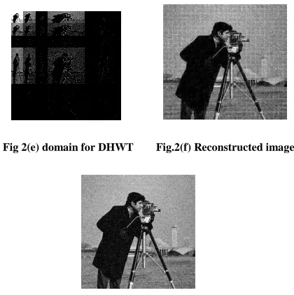
In Haar wavelet original image can be sub divided into 4 sub images. DHWT sub divides the original image into 9 sub images In Moving window based DHWT the size of the window can be fixed as per our wish, But this can in the form 3n X 3n.The main advantage in MWDHWT is the PSNR &SNR will be so high when compared with HWT and DHWT.because the wavelet can be applied more than once according to algorithm.The image of cameraman with 256X256 pixels, which is considered as reference to this project is shown in Fig.2(a).
The image which is corrupted with Gaussian noise of variance of 0.005 and zero mean is shown in Fig2(b). Its PSNR value is 23.5127 dB. From this, it gives that Moving Window-Based Double Haar Wavelet technique has produce higher SNR and PSNR values compared to Haar wavelet and Double Haar wavelet transform.
Fig.2(a) Original Image Fig.2(b) Noisy input
Fig.2(c)Haar Wavelet Fig.2(d)Haar Wavelet output
Fig 2(e) domain for DHWT Fig.2(f) Reconstructed image
Fig.2(g) Reconstructed image with MWHWT.
VII. CONCLUSIONS
Experimental results indicate that the new method of noise reduction significantly outperforms a standard procedure which is used to restore contaminated images with Gaussian noise. The new technique is fast and very easy to implement. As can be seen, the new class of wavelets eliminates efficiently Gaussian noise, while preserving important image structures like edges, corners, lines and fine texture. The application of “moving window-based double Haar wavelet transform for image enhancement” can be well studied for weather forecasting purposes, medical related areas. In weather forecasting the Gaussian noise reduction wavelet is used to remove the Gaussian noise on satellite images. In medical applications this wavelet is used to remove the noise on the X-ray’s.
REFERENCES
[1 ] Rafael C. Gonzalez and Richard E. Woods, “Digital Image Processing”, Prentice Hall Publications, Second edition, 1992 [2 ] Insight into wavelets from theory to practice B.KP.Soman,
K.I.Ramachandran, 2
nd
edition.
[3 ] Rafael C. Gonzalez and Richard E. Woods, “Digital Image Processing Using MATLAB”, Prentice Hall Publications, Second Edition, 1992
[4 ] M.Hansen and B.Yu, “Wavelet thresholding via MDL for natural images”IEEE Trans Inf.Theory,Vol 46,no. 8 ,pp.1778 -1788, Aug 2000
Haar
dhwt
Mwdhwt
threshold
0.3548
0.3464
0.3464
SNR(dB)
17.8980 15.1673
20.8128
[image:4.612.58.270.134.286.2] [image:4.612.345.555.142.353.2]International Journal of Emerging Technology and Advanced Engineering
Website: www.ijetae.com (ISSN 2250-2459, Volume 2, Issue 9, September 2012)74
[5 ] S.G.Chang, B.YU and M.Veterli, ”Adaptive wavelet thresholding for image enhancement and compression”, IEEE Trans .Image Process,Vol 9, no. 9,pp. 1532-1546,Sept 2000
[6 ] Xin Wang “Moving Window-Based Double Haar Wavelet Transform For Image Processing”,IEEE Trans .Image Process Vo15, no. 9, pp. 2771-2779, Sept.2006 .
AUTHORS
G.Venkateswarlu, Pursuing M.Tech DECS branch in SBIT, khammam. B.Tech ECE at SBIT, Khammam. His research interests include image processing applications .
B.Jayanthnadh, received his B.Tech degree in electronics and communication engineering from JNTUH,a.p,india and M.Tech in embedded systems from JNTUH .He presently working as an assistant professor in Swarna Bharathi Institute of science and Technology(SBIT) khammam.ap,india. His research interests include image processing applications and communication systems, embedded systems. He had two years of experience in SED,ECIL Hyderabad.