A Petri net-occam based methodology for the development
of dependable distributed control software.
GRAY, Peter A.
Available from Sheffield Hallam University Research Archive (SHURA) at:
http://shura.shu.ac.uk/19716/
This document is the author deposited version. You are advised to consult the
publisher's version if you wish to cite from it.
Published version
GRAY, Peter A. (1995). A Petri net-occam based methodology for the development of
dependable distributed control software. Doctoral, Sheffield Hallam University
(United Kingdom)..
Copyright and re-use policy
frrVN 3fe1
Sheffield Hallam University
ProQuest N um ber: 10697018
All rights reserved
INFORMATION TO ALL USERS
The quality of this rep ro d u ctio n is d e p e n d e n t u p o n the quality of the copy subm itted.
In the unlikely e v e n t that the a u th o r did not send a c o m p le te m anuscript and there are missing p a g e s , these will be n o te d . Also, if m aterial had to be rem o v ed ,
a n o te will in d icate the deletio n .
uest
P roQ uest 10697018
Published by ProQuest LLC(2017). C opyright of the Dissertation is held by the Author.
All rights reserved.
This work is p ro tected a g a in st u n au thorized copying under Title 17, United States C o d e Microform Edition © ProQuest LLC.
ProQuest LLC.
789 East Eisenhower Parkway P.O. Box 1346
A Petri Net-Occam Based Methodology
for the Development of Dependable
Distributed Control Software
Peter Andrew Gray
BSc MTech MSc
A thesis submitted in partial fulfilment of the
requirements of Sheffield Hallam University
for the degree of Doctor of Philosophy
Abstract
Analysis of flexible manufacturing cells (FMCs) shows their requirement for flexible, correct, reliable, safe and distributed control. A comparison of the state of the art in software engineering for parallel systems, and an examination of safety related systems, reveal a need for formal and rigorous techniques at all stages in the software life cycle. However, parallel software, safety related software and formal techniques are complex. It is better to avoid faults rather than eliminate or tolerate them, and although less flexible, avoidance is often simpler to implement.
There is a need for a tool which overcomes many of these complexities, and this thesis discusses and defines such a tool in the form of a methodology. The novelty of the work is in the combination of the core goals to manage these issues, and how the strategies guide the user to a solution which will not deadlock and which is comprehensible.
Place-transition Petri nets are an ideal representation for designing and modelling the interaction of concurrent (and distributed) processes. Occam is a high level real time parallel language designed to execute on one or a network of transputers. Transputers are processing, memory and communication building blocks, and, together with occam, are shown to be suitable for controlling and communicating the control as the DCS in FMCs.
The methodology developed in this thesis adopts the mathematically based tools of Petri nets, occam and transputers, and, by exploiting their structural similarities, incorporates them in a steps and tasks to improve the development of correct, reliable and hence safe occam code. The four steps: identify
concurrent and sequential operations, produce Petri net graphs for all controllers, combine controller Petri net graphs and translate Petri net graphs into occam; are structured around three core goals: Petri
net/occam equivalence, comprehensibility and pro-activity; which are manifest in four strategies: output- work-backwards, concurrent and sequential actions, structuralise and modularise, and deadlock
avoidance.
Contents
1. Introduction...1
1.1 Research Applicability...1
1.2 Traditional Production M ethods...1
1.3 Flexible Production... 2
1.4 Shortening Order-to-delivery and Manufacturing Lead Time...2
1.5 Shortening Time-to-market and Product Development Time...4
1.6 Integrated Flexible Production Systems...5
1.7 Fast Reconfiguration Requirement in FM Ss...6
1.8 The Research and Thesis...7
2. The Flexible Manufacturing Cell and Its Communication...9
2.1 Introduction... 9
2.2 Flexibility and Cellular M anufacturing... 9
2.3 Description of Existing PC Based C ell... 10
2.3.1 Choice of Component...10
2.3.2 Conveyor Track... 12
2.3.3 Pallets... 13
2.3.4 Transfer and Local Work Handling Equipment... 13
2.4 Control and Communication of Control... 15
2.5 The Control of the Existing PC Based FM C...21
2.6 The Communication of the Existing FMC...23
2.6.1 The LAN and PC Hardware and Software... 25
2.6.2 LAN Software... 25
2.7 Summary of Problems and Manufacturing Requirem ents... 27
3. Tools and Techniques in Dependable Distributed Control....29
3.1 Introduction...29
3.2 Dependability...29
3.2.1 Software Engineering... 29
3.2.2 Correctness...30
3.2.2.1 Validation and Verification...32
3.2.3 Reliability...33
3.2.4 Safety... 34
3.2.4.1 Safety Standards...34
3.2.4.2 Safety Integrity Level...36
3.2.4.3 Hazard Analysis...38
3.2.5 Software and Hardware... 38
3.3 Petri Nets... 40
3.3.1 General Petri N ets...40
3.3.1.1 Characteristics of Petri N ets...40
3.3.1.2 Petri Net Graphs...40
3.3.1.3 Firing rules... 42
3.3.1.4 Petri Net Properties... 42
3.3.1.5 Petri Net Analysis... 43
3.3.1.6 Reachability Tree...43
3.3.2.3 High Level Petri Nets...45
3.3.2.4 State Transition Diagrams (STDs)... 46
3.4 Occam and its Dependability...46
3.4.1 The Occam Language and Programming Environment...46
3.4.2 The Occam Toolset... 48
3.4.3 Occam Safety...49
3.4.4 Deadlock Correctness... 49
3.5 A Comparison of Transputers and other Shop Floor Controllers... 50
3.5.1 Distributed Control Systems and Networks...51
3.5.2 Models of Communication and Synchronisation...52
3.5.3 Communication Standards...55
3.5.4 Shop-floor Communication...57
3.5.5 The Transputer and Occam...57
3.5.5.1 Transputer Reliability...58
3.5.5.2 Transputer Communication... 58
3.5.5.3 Transputer Communication Reliability... 58
3.5.5.4 Occam and Transputer Communication... 59
3.5.5.5 Booting... 59
3.5.5.6 Configuration...60
3.5.5.7 The Transputer and the O SI7 Layer Reference Model...60
3.5.6 FIP (Factory Instrumentation Protocol)...61
3.5.7 Mini-Map with MMS... 62
3.5.8 9Tiles... 62
3.5.9 A Comparison Shop-floor Control Systems... 63
3.6 Similarities between Petri Nets and Occam...65
4. Distributed Control Development...66
4.1 Introduction...66
4.2 Software Engineering for Parallel Systems...66
4.2.1 A Review of the State of the A rt... 68
4.3 Concurrent and Distributed Processing... 70
4.4 Formal Development... 71
4.4.1 Informal, Formal and Rigorous Techniques... 71
4.4.2 Formal Methods...72
4.4.3 Formal Development Life-Cycle... 74
4.4.3.1 Requirements Analysis...74
4.4.3.2 System Specification... 75
4.4.3.3 Architectural Design... 76
4.4.3.4 Detail Design...76
4.4.3.5 Coding...76
4.5 Comprehensibility and Creativity...77
4.5.1 Idea Generation... 77
4.5.2 The Creative Process...77
4.5.3 Media for Development and Recording Creativity...77
4.5.4 Modelling Methods...78
4.5.5 Idea communication...78
4.5.6 The First Creative Steps... 78
4.5.7 A Repeated Procedure...78
4.5.8 Comprehensibility of Formal Methods...78
4.5.9 Conclusions...79
4.6 Petri Net Graphs and Pseudo Code...79
4.6.1 Petri Net Graphs and Pseudo Code in Modelling and Design... 79
4.6.1.1 Model Description or Representation...79
4.6.1.2 Description Detail Versus Visualisation...80
4.6.1.4 Granularity...82
4.6.2 Analysis Capabilities... 83
4.6.3 Conclusion... 83
4.7 Development with Petri Nets with O ccam ...83
4.7.1 Modelling Occam In Petri Nets... 83
4.7.1.1 Carpenter... 83
4.7.1.2 X u...84
4.7.1.3 Steinmetz... 84
4.7.1.4 Best...84
4.7.2 Performance... 84
4.7.2.1 Balbo...84
4.7.3 CASE Tools... 84
4.7.3.1 MARS... 84
4.7.3.2 Breant...85
4.7.4 Designing Petri Nets for Occam... 85
4.7.4.1 Kerridge... 85
4.7.4.2 Gorton...86
4.7.5 Tools for Designing Petri Nets and Occam... 86
4.7.5.1 Lau... 86
4.7.6 Designing Safety Systems with Petri Nets and Occam... 87
4.7.6.1 Birkinshaw...87
4.7.7 Non Petri Net Graphical Methodologies for Occam Code Production...89
4.7.7.1 Manson... 89
4.7.7.2 Jelly...90
4.7.7.3 Schafers... 91
4.7.8 Observations and Conclusions from the Examples...92
4.8 Occam Development Examples...93
4.8.1 Data Flow Diagrams...94
4.8.2 Programming Style...94
4.8.3 Occam Transformations... 95
4.8.4 The Design Phase of Software Development... 95
4.8.5 Models of Parallelism... 97
4.8.6 Discussion...97
4.9 M utual Exclusion... 97
4.10 Deadlock... 97
4.10.1 Conditions for Deadlock... 97
4.10.2 Deadlock Detection in Occam...100
4.10.3 Deadlock Elimination in Occam...101
4.10.4 Deadlock Avoidance in Occam...102
4.10.5 Discussion...104
4.11 A Comparison with SIFT ...104
4.12 Conclusions...105
4.12.1 The Needs of a Transputer Based FM C...105
4.12.2 The Needs of an Occam Based Methodology... 106
4.12.3 The Use of Petri Nets with Occam...107
4.12.4 Criticism of the Current Use of Petri Nets and Occam...108
4.12.5 Techniques Useful to a Petri Net Occam Based Methodology...109
5. Methodology for Design and Implementation o f a DCS...110
5.1 Introduction... 110
5.2 Aims of the Methodology...110
5.3 Techniques and Considerations in the Methodology...110
5.3.4 Concurrent and Sequential Actions...111
5.3.5 Deadlock Avoidance...I l l 5.3.6 Output-work-backwards... 112
5.3.7 Steps and Tasks... 112
5.3.8 Modularise and Structuralise... 113
5.3.9 The Need for a Cell Controller and Status Handler...113
5.3.10 Petri net entry places become occam alternatives... 113
5.3.11 Simple and Complex Places...117
5.3.12 Pseudo-code and Place Descriptions... 117
5.3.13 The Human Computer Interface...117
5.3.14 Testing...117
5.3.15 Timing...118
5.4 Core Goals and Strategies...118
5.5 The Description of the Methodology...120
5.6 Step 1- Concurrent and Sequential Operations... 121
5.6.1 Task 1 Identify concurrent and sequential operations... 121
5.6.2 Task 2 Create cell controller and status handler...121
5.7 Step 2- Produce Petri Net Graphs for each Controller... 121
5.7.1 Task 1 Identify the outputs for the controller... 121
5.7.2 Task 2 Draw the controller’s boundaries...123
5.7.3 Task 3 Draw ‘exit places’...123
5.7.4 Task 4 Draw a transition and arc for each exit place... 125
5.7.5 Task 5 Determine transition inputs... 125
5.7.6 Task 6 Draw the transitions’ input places and arcs...125
5.7.7 Task 7 Repeat tasks 4,5 and 6 ...126
5.7.8 Task 8 Consolidate entry and exit places...126
5.7.9 Task 9 Initial conditions... 126
5.8 Step 3- Combine Controller Petri Net G raphs... 130
5.9 Step 4- Translate Petri Net Graphs in to Occam... 130
5.9.1 Task 1 Names are Preserved...130
5.9.2 Task 2 Overall procedure... 131
5.9.3 Task 3 Controller procedures... 131
5.9.4 Task 4 Entry and exit places become channels... 131
5.9.5 Task 5 Transitions become IFs...132
5.9.6 Task 6 Initial conditions...132
6. Discussion o f the Methodology...133
6.1 Introduction... 133
6.2 Step 1 - Analysis of the FMC...133
6.3 Step 2 - Controller Petri Net Graphs...134
6.3.1 Starting Approaches...134
6.3.2 Communication... 134
6.3.3 Petri net and Occam Differences...135
6.3.4 Naming and Referencing Conventions... 135
6.3.5 Workstation Controllers...138
6.3.6 Cell Controller...141
6.3.7 Status Handler...144
6.4 Step 3 - Synthesis of the Controller Graphs...151
6.4.1 Graph Positioning... 151
6.4.2 Inter-Controller Communications...151
6.5 Step 4 - Conversion to Occam... 151
6.5.1 Naming Conventions...151
6.5.2 Procedure Formats... 153
6.5.4 Cell Controller... 153
6.5.5 Status Handler... 154
6.5.6 Master Procedure...155
6.5.7 Termination... 156
6.5.8 Pseudo code... 161
6.5.9 Configuration for Transputers and Links...162
6.6 Application to Other DCSs... 162
6.7 Overall Discussion... 162
6.7.1 The Methodology Meets its Aims... 162
6.7.2 The Needs of Methodologies...164
6.7.3 The Design of the Methodology...165
6.7.4 Specification Observations...172
6.7.5 Coding Observations...175
6.7.6 Specification Validity...176
6.7.7 The relationship between Levels 1 and 2 ...177
6.7.8 Boolean Algebra...177
6.8 Comparison of the Methodology with Other Applications...178
7. Conclusions and Recommendations...181
7.1 Conclusions...181
7.2 Recommendations for Further Work... 183
Appendices...188
Figures
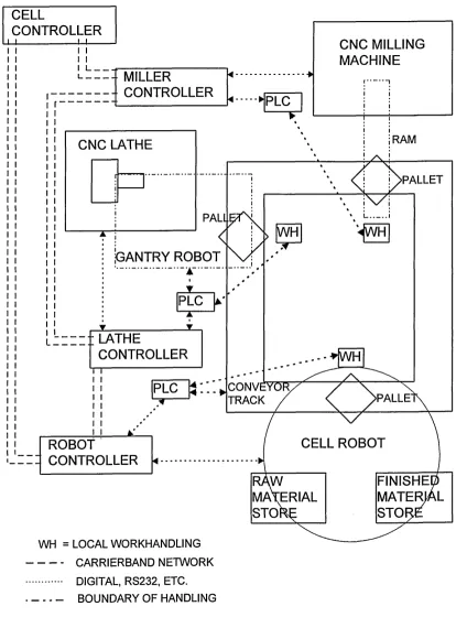
Figure 2-1 The layout of the FMC showing cell robot, lathe and miller workstations around the
conveyor, and their controllers...11
Figure 2-2 Two typical parts, one for turning only, one for turning and milling... 14
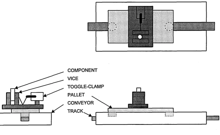
Figure 2-3 Three views of a component, vice, pallet and conveyor tra c k ... 14
Figure 2-4 Workstation modules consist of process, transfer device and local work handling 16 Figure 2-5 Robot workstation consists of cell robot, raw and finished material stores and local work handling... 16
Figure 2-6 Lathe workstation consists of lathe, gantry robot and local work handling... 17
Figure 2-7 Miller workstation consists of miller, pneumatic ram and local work handling...17
Figure 2-8 Corporate CIM hierarchies for a) control, and b) communication... 22
Figure 2-9 A combined control and communication hierarchy of the FM C... 22
Figure 2-10 Buffer insertion ring network with 3 nodes, one transm itting...24
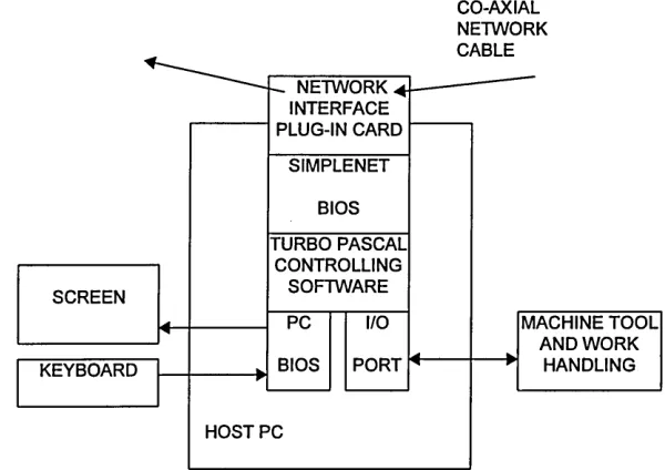
Figure 2-11 Ports of a PC based node: network, workstation, screen and keyboard... 24
Figure 3-1 Software development life cycle, showing processes and deliverables...31
Figure 3-2 An example formal software development life cycle [McDermid]... 31
Figure 3-3 A life cycle for safety critical software... 35
Figure 3-4 Risk level determines safety integrity and rigour of technique...35
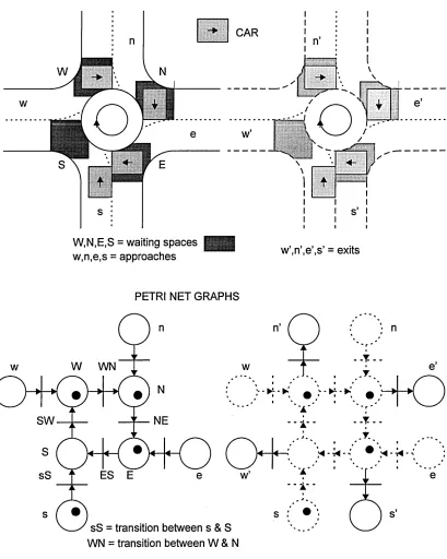
Figure 3-5 A Petri net graph consists of places, transitions, input and output arcs...41
Figure 3-6 Arc weighting or multiplicity shown with multiple arcs or a num ber...41
Figure 3-7 A Petri net before and after firing...41
Figure 3-8 Source transitions generate tokens...41
Figure 3-9 Sink transitions consume tokens...41
Figure 3-10 Self loops before and after firing...41
Figure 3-11 Inhibitor arcs used to model NOT, exclusive OR (EOR), switch and priority...44
Figure 3-12 Communication in Petri nets and occam...44
Figure 3-13 Petri net and occam equivalences...44
Figure 3-14 a) 5 nodes connected by b) point-to-point c) ring and d) bus...54
Figure 3-15 Client-server model of communication in MMS... 54
Figure 3-16 Producer-consumer model of communication in FIP...54
Figure 3-17 The full 7 layer OSI and cut-down 3 layer Fieldbus models... 56
Figure 3-18 A network extended by a bridge or repeater at layer 2 or 1... 56
Figure 3-19 Different networks connected by router or gateway at layer 3 or 7 ... 56
Figure 4-1 Parallel software development life cycle... 67
Figure 4-2 A transition decomposed into a sub-net - preserving synchronisation...81
Figure 4-3 A place decomposed into a sub-net - preserving m arking... 81
Figure 4-4 Petri net and occam models of mutual exclusion... 98
Figure 4-5 An example of deadlock showing Petri net model and reachability tree...99
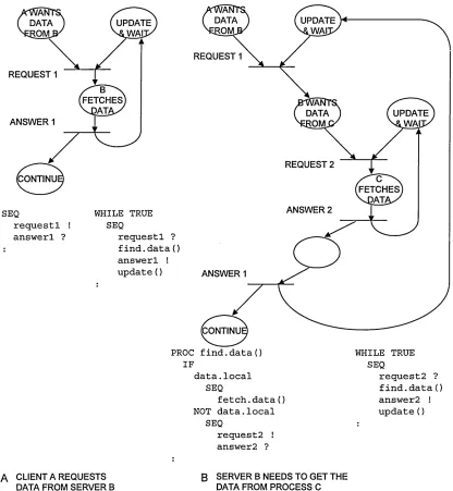
Figure 4-6 Client-server communication, in Petri net and occam form ... 103
Figure 5-1 Occam (a) and abstract (b,c) and real (d,e) Petri net models of a fair and unfair ALT 114 Figure 5-2 Occam template or generic controller procedure, and its Petri net equivalent...115
Figure 5-3 Task 2 of step 2 - draw controller boundaries...122
Figure 5-4 Task 3 of step 2 - draw exit places... 122
Figure 5-5 Task 4 of step 2 - draw a transition and arc for each exit place...122
Figure 5-6 Task 6 of step 2 - draw transition’ input places and arcs...124
Figure 5-7 Conditions to load, start and unload the lathe, in the cell controller, with duplicate places...124
Figure 5-8 Conditions to load, start and unload the lathe, in the cell controller, showing mutual exclusion rather than duplicate places... 127
Figure 5-9 Conditions to load, start and unload the lathe, after consolidation...128
Figure 5-10 Conditions to load and unload the robot in the cell controller...128
Figure 5-11 Conditions to load, start and unload the miller in the cell controller... 129
Figure 6-1 Lathe controller development of step 2; a) tasks 1-3 and b) tasks 4-6 outputting to level 1 controllers; c) tasks 1-6 outputting to the status handler... 137
Figure 6-2 Combined lathe controller showing sequence (read downwards) and rearranged reference num bers... 139
Figure 6-3 Robot controller Petri net graph... 139
Figure 6-4 Miller controller Petri net graph... 140
Figure 6-6 Condition index allowed in the cell controller... 142
Figure 6-7 Condition index wanted in the cell controller...143
Figure 6-8 Lathe statuses in the status handler...145
Figure 6-9 Robot statuses in the status handler...145
Figure 6-10 Miller statuses in the status handler... 146
Figure 6-11 Rotate pallet statuses and conveyor statuses...146
Figure 6-12 Reduction of excessive place replication of Figure 6-8... 147
Figure 6-13 Pallet at lathe statuses in the status handler...148
Figure 6-14 Pallet at robot statuses in the status handler...149
Figure 6-15 Pallet at miller statuses in the status handler... 150
Figure 6-16 Occam code for the lathe controller... 152
Figure 6-17 Termination due to end of parts list... 157
Figure 6-18 Termination conditions in the cell controller...157
Figure 6-19 Petri net and pseudo code abstractions of Figure 6-14...158
Figure 6-20 Pseudo code for Figure 6-19... 159
Figure 6-21 Occam code for Figure 6-19... 160
The labyrinth Petri net graph - before the methodology inside back cover The overall Petri net graph - after the methodology...inside back cover
Tables
Table 2-1 Flexibilities of FMSs...9Table 2-2 Four types of FMS and their routing flexibilities...10
Table 2-3 Chess piece codes translates in to part program ... 12
Table 2-4 Simple job list for the FMC generated from the codes of Table 2-3...12
Table 3-1 Accident severity categories...37
Table 3-2 Probability ranges...37
Table 3-3 Risk classification of classes...37
Table 3-4 Interpretation of risk classes...37
Table 3-5 Assignment of safety integrity levels...39
Table 3-6 Claim limits... 39
Table 3-7 Comparison of occam and Pascal... 47
Table 3-8 Function of the 7 layers of the OSI reference model... 55
Table 4-1 Four doubts inherent in development specifications... 72
Table 4-2Verification techniques... 104
Table 6-1 Petri net and occam equivalence... 168
Table 6-1 Tools, techniques and verification for the methodology...172
Table 6-2 Comparison of the methodology and applications against the goals and strategies 178
Plates
Plate 1 The FMC with cell robot, lathe and miller workstations... 18Plate 2 The conveyor...18
Plate 3 A pallet holding a part. Local pneumatic work handling... 19
Plate 4 The robot workstation...19
Plate 5 The lathe workstation with lathe and gantry robot...20
Dedication
My father and maternal grandmother died while I was studying for this degree. I wish to dedicate this thesis to their memory, and to my mother.
Acknowledgements
I would like to express my sincere gratitude to my supervision team: Dr W Hales, Mr A Goude and Prof F Poole, and to Prof E Lo and Mr G Cockerham who encouraged my return.
Thanks also to friends, colleagues, technicians and security staff.
Declaration
I declare while registered as a candidate for the University’s research degree, I have not been a registered candidate or enrolled student for another award of the University or other academic or professional organisation. I further declare that no material contained in this thesis has been used in any other submission for an academic award.
1. Introduction
1.1 Research Applicability
Flexible manufacturing cells (FMCs) are at the heart of some modem production methods. Flexibility, in rapidly changing markets, is a distinct competitive advantage. Being able to alter flexible production facilities to meet market demands requires a tool to facilitate the development of manufacturing control and to produce the software to implement that control and communicate that control to the machine tools and work handling equipment of an FMC. The tool, the research methodology, presented in this thesis, is a combination of two existing tools and a set of rules.
Flexible production seems to cope with current market conditions better than traditional methods. Markets want more variety, developed and manufactured quicker.
The introduction begins by comparing production methods, then outlines strategies aimed at improving manufacturing and product development times, and gives examples of their use in the car industry. Many of the strategies discussed achieve flexibility through the use of computers, in product development (CAD), for future FMC layouts (CAPP) or in manufacturing control (CAM) of currently operating machine configurations, and are considered for planned and actual transputer implementation. The introduction ends with the evolution and boundaries of the research and the structure of the thesis.
1.2 Traditional Production Methods
Until the mid 1980’s the predominant reliable production techniques available to manufacturers of discrete components were craft, mass and batch production[Mair 1993].
In craft production, a worker skilled in a range of manufacturing processes can produce a low volume of high quality products to the customers’ specifications. The worker, like his environment the job-shop, is general-purpose and flexible. The worker is able to manufacture the components in any order, in any suitable route between machines, and fits them together. Generally one product is made at a time, and premium prices can be charged for quality and exclusivity.
In mass production, companies specialise production (machines and labour) to make high volumes of toleranced components and assemble them into a limited variety of standardised products. Material flow in manufacturing and assembly is linear and continuous. High stocks are made at all stages of production to prevent stoppages. This is crucial in assembly, but due to low quality many products must be repaired or scrapped. Low cost per unit is attained by high volumes, specialisation and standardisation.
In batch production, components are manufactured within tolerances, and are taken to each
In mass production, machine tools are customised to manufacture individual components, whereas such specialisation is absent in craft production. General-purpose and semi-automatic (e.g. capstan lathes) machine tools and batch-specific jigs and fixtures are used in batch production. This leads to batch production being more efficient but less flexible than craft production, and more flexible but less efficient than mass production.
1.3 Flexible Production
Customers have always had an infinite variety of wants [McCormick 1977], but are limited by their income, and therefore make choices and demand products with the lowest prices. Manufacturers can provide a high volume of standard low cost products (mass production), a low volume of high cost customised products (craft production), or a variety of medium to high cost products in low to medium quantities (batch production), but have been unable to manufacture a wide variation of products at relatively low cost and at a quality and quantity to suit the customer.
Flexible production [Morales 1994] has presented an extra dimension to production, with the maturation of reliable computerised and co-operating development and production processes. Rather than mass production competing on cost per unit, craft production on quality and exclusivity and batch production interposing, manufacturers, using flexible production, are finding and serving niche markets and competing on flexibility whilst achieving relatively low cost and high quality. The benefits of flexibility include: introducing new products quicker, producing many variations, coping with different order sizes, supplying customised items and limited editions, and manufacturing for new markets.
To fully service the competitive advantage of flexibility, manufacturers must reduce time-to-market (which includes product concept, development, manufacture and launch) and/or order-to-delivery time (which includes manufacturing lead time). In market or customer orientated competition, responses must be swift and flexible. The marginal cost of flexibility using computerised development and
manufacturing processes is relatively low, but the premium prices (possible through satisfying customer demand) must be charged to recoup the high capital investment in advanced technology plant and the necessary changes in corporate organisation, strategies and management processes. Strategies available to help shorten the manufacturing lead and product development times are given in sections 1.4 and 1.5.
1.4 Shortening Order-to-delivery and Manufacturing Lead Time
Order processing, production and delivery must be able to cope with batches of the size of a typical order. Work-in-progress and through-put time must be minimised, and bought-in parts must be available quickly. Production processes will have to be flexible to cope with different products and fast changes in batches of products. Strategies to help shorten order-to-delivery time are group technology, cellular manufacturing, flexible manufacturing, just-in-time and flexible manufacturing systems:
Group Technology (GT)
processes or machines, which greatly reduces set-up times per batch. The lay-out of the machines can either be random (job-shop flow), or can reflect the manufacturing order of the processes/operations (uni directional or line flow), but in both cases the close proximity of the machines reduces material handling time and improves through-put.
Cellular M anufacturing (CM)
[Williams 1994] gives three views of cells:
• cells usually contain a small number of closely co-operating machines sharing dimensional data, floor-space and human workers
• biologically - cells are the smallest autonomous unit capable of sustained production • automated manufacture- cells are a subset of group technology
CM [Opitz 1971] uses batch production, the parts' families and machine layout techniques of GT, and generally uses uni-directional material flow. A family of parts can be manufactured on one group of machines, and those machines are grouped close together in a cell. Movement of material between cells is also minimised to reduce material handling and improve through-put. A cell is relatively independent, this and its other characteristics need simple control, which renders it ideal for automation and computer control.
Flexible Manufacturing (FM)
Automation [Mair 1993] improves the quality and the through-put speed of components, via precise, repeatable, fast and prior determination of machine set-ups (via cam, pneumatic, or electrical actuators). It reduces the need for, changes the function of, and improves the working condition of labour.
Integrating computerised controllers with automated machines and materials handling equipment makes them more flexible. Computer numerically controlled (CNC) machines, such as CNC machine tools, machining centres and robots, can perform a sequence of operations that are initiated by a given, or stored, list of instructions (a part program). CNC machines controlled by part programs offer many advantages:
• the number and order of automatic operations are not governed by mechanical (e.g. turret indexing) or hard-wired (e.g. peg-board) limitations
• machining complexity is not limited by the intelligence of the machine’s CNC controller, because data can be supplied directly from a larger computer
• tools can be automatically selected from a carousel
• workers are not confined to operate one machine, but can mind many CNC machines, however safety becomes an issue
machine tools and material handling equipment. The manufacturing control is run as software on the supervisory and controller computers at the same time (concurrently). The control is communicated between the supervisory and controller computers and on to the CNC machine tools and material handling equipment. Communication is handled by a computer network, which consists of computer nodes (supervisor and controller computers), cable and network software. FMCs can be fully automatic, and relegate workers to auxiliary tasks within the manufacturing environment, which can present a safety problem.
A co-ordinated collection of FMCs with inter-linking material handling makes up the FMS. Each family of components is manufactured in an FMC, and can be assembled with other components from other FMCs in a flexible assembly system (FAS) to form the products. The FMS can be a part of larger environments by integrating design with manufacture as in CADCAM, or integrating many corporate processes as in CIM (see section 0). An FMS can exhibit machine, operation, process, product, routing, volume, expansion and production flexibilities (see Table 2-1).
Team-working
A team of multi-disciplined labour works together in a group or cell [Gray 1994]. The team is
empowered to make decisions necessary to maintain and improve high quality, flexibility and through put. Teams are responsible for scheduling stock and meeting delivery times. Long-term education is planned by the team for its members.
Just-In-Time (JIT)
JIT [Voss 1988] concentrates on flow, flexibility and a chain of supply, with strategies of minimal stock and team-working. It adopts batch production, CM and FM, but develops a chain of co-operating suppliers. To facilitate the short through-put times and low work-in-progress, measures such as preventative maintenance, quality, team-working, inventory control and design for simplicity of manufacturing are generally implemented.
1.5 Shortening Time-to-market and Product Development Time
[BS 7000 1989] gives steps in the evolution of a product, and indicates the ‘creation’ processes which are the design and manufacture disciplines of product development. Statistics [Gould 1992] indicate that 60- 80% of the product cost is pre-determined at the design stage, and that 50% of design time is spent on redesigns sent back by the manufacturing department because the design could not be made. Strategies to help shortening time-to-market (TTM) are concurrent engineering and design for manufacture:
Concurrent or Simultaneous Engineering
in the feasibility study and specification. Also, late changes in manufacturing can immediately be assessed in terms of market response or design implications. The breakdown of barriers between
corporate departments is necessary, including the integration of their computer systems into a CADCAM or CIM environment.
Design for Manufacture (DFM)
DFM implies that decisions made earlier in product development (in design) will influence those made later (in manufacture), so should be made with regard to them, or even in conjunction with them [Morgan 1988]. The design or manufacturing engineer is fully stretched by the demands of his or her discipline, so it is unlikely that an individual will be effective in both disciplines unless aided by an integrated
computerised CAD and CAM tool. Here the designer could try a number of designs and the tool could quickly highlight or simulate the manufacturing, and possibly the production, consequences. This could preclude the building and testing of a physical model or prototype, and speed up the overall product development process.
1.6 Integrated Flexible Production Systems
Two integrated production environments that combine some of the above strategies for improving order- to-delivery and time-to-market are CIM and lean production:
Computer Integrated Manufacturing (CIM)
The use of computers can improve flexibility, processing, control and communication, as seen in FM and FMC above. Increases in flexibility and processing are evident in the application of computers in the manufacturing, design, production engineering, storage and transportation, and production planning departments in CAM, CAD, CAPE, CAST and CAPP systems [Yeoman 1985]. Information about components, machines, costs, personnel and other resources is common to many of these manufacturing business processes, and should not be held separately and so be replicated. CIM [Thompson 1987] is a corporate-wide information technology (IT) skeleton to service and share manufacturing information. Information entered via one computer system can be accessed by anyone in the company on another system. It does not have to be entered again, and everyone’s information is up-to-date. Systems with different computer hardware, operating system and application software must be integrated so connections are invisible to the users. ‘Open systems inter-connect’ (OSI) [BS-ISO 7498 1984] is an international standard to assist in this connection.
Lean Production
This hybrid adopts many of the techniques to improve time-to-market and order-to-delivery time [Gray 1994]. Its aims are to make the most of flexibility, quality, human resources, working capital and floor- space. It therefore uses JIT inventory control, FMSs, quality control, team-working design for
Production in the Car Industry
Some of the above strategies were developed by automotive producers [Gray 1994]. General Motors pioneered the Manufacturing Automotive Protocol (a specific form of OSI) and Toyota developed JIT. Lean production is being pursued by almost all of the world’s major car companies to produce high quality and low cost products, in the high volumes and increasing variety demanded, with flexibility and shorter delivery times, and shorter time-to-market for new models. The result is that the average time to assemble a car has reduced by about 20% and TTM by about 25%.
1.7 Fast Reconfiguration Requirement in FMSs
Manufacturers who work to a TTM of a few months for a variety of components or products often have to change the floor layout or machine configuration of their FMS. Mostly the changes will be planned, but unpredicted alterations will also have to be made during normal operation, whilst the FMS is under real time control. A change in configuration could be:
• a machine replacement due to up-grade or maintenance
• an expansion of the FMS with a new FMC or more work handling, or of the FMC with a new machine or robot
• a cell replacement because of a new family of parts
• a re-routing due to machine breakdown or special component requirement
A conceptual reconfiguration or simulation must enable feasible alternatives to be developed, before the chosen configuration is implemented. Swift and dependable reconfiguration is needed for planned and unpredicted changes for safe, reliable and correct operation.
The planning, implementation and control of manufacturing strategies, and the manufacturing control, are largely the concern of the manufacturing engineers, while the communication of that control in an FMC is dealt with by the computer hardware and software engineers. Where speed of connection and re connection of CNC machines and network computers is important, then a modular approach with
common CNC and computer interfaces may be needed. In this way, once the configuration is decided, the implementation includes locating the appropriate machines and material handling, plugging together the network computers and plugging the machines and material handling into the network and loading the appropriate control software. This will enable the manufacturing engineer to manage the reconfiguration more quickly, and with reduced need for consultation with computer hardware and software engineers.
The transputer, “the computer on a chip” (see section 3.5.5), is a relatively cheap, reliable and fast microprocessor. It consists of processing, memory and communications, which makes it an ideal building block for use in networks. A variety of hardware is available to interface transputers with the CNC or PLC controllers of the machine tools and material handling equipment.
The connection of hardware is trivial compared with the design of manufacturing control and
communication software. The properties of transputers, and the programming languages that run on the transputer, e.g. occam, lessen both problems. However, there is a need for rapid development of software. This thesis describes a methodology, which enables the rapid development of flexible, comprehensible and dependable occam code.
1.8 The Research and Thesis
Research Evolution
The original research was to transputerise the University’s FMC, and to formulate and carry out
performance comparisons. Occam immediately was chosen as the transputer programming language, and general place-transition Petri nets were found to be a suitable modelling tool. A Petri net model of the FMC was constructed, and software was written to run on a single transputer. The formal characteristics of occam and Petri nets strongly influenced the change in research to a transputer controlled FMC. A relationship between occam and Petri nets was found that confirmed earlier work [Carpenter 1987]. Limitations in their inter-relationship and the difficulty in understanding large Petri nets, refer to the ‘labyrinth’ Petri net graph (inside the back cover), were the motivation for the methodology documented in this thesis.
Research Boundaries
FMSs are becoming more widely used, in different industries, containing various processes, producing larger output volumes in smaller batch sizes, so require reconfiguring more often and quickly. There is a need for a methodology that can help plan the manufacturing control and then help implement the communication of that control on a network of transputers and transputer-fronted CNC machine tools and material handling equipment.
The methodology is confined to the control and the communication of control for an FMC. It must:
• enable the modelling and design of synchronising and communicating concurrent manufacturing processes in an easily understandable way
• enable the production of correct, reliable and safe software
• allow the swift reconfiguration of machine tools and material handling for both planning and control • facilitate future growth of, and modifications to, the cell
• handle, in real time, the variety and quantity of data communicated
The methodology exploits two mathematically based tools, Petri nets and occam, but its rules make no reference to mathematics. This should be attractive to industry, where there is a reluctance to adopt formal methods because of their complexity and difficulty of use. Consequently the research is non- mathematical, and the thesis only mentions mathematics in further work and appendices.
Thesis Structure
methodology. Chapters 5 and 6 describe and discuss the methodology, and how it can be implemented in the example FMC. The remaining chapters highlight the work done, the work to be done and the
conclusions.
The University’s FMC is used as an example to illustrate the problems involved with an FMC. The execution of its function, the FMC’s manufacturing control, and its means of distributing the function, the communication of control, are detailed in chapter 2. The safe, reliable and correct operation of an FMC can only be achieved if the constituent hardware and software have been developed to operate reliably and correctly. Chapter 3 discusses these issues, and compares alternative suitable tools and techniques, and examines the chosen modelling and programming tools, Petri nets and occam. Software engineering for DCSs is discussed in chapter 4, focusing on comprehensibility throughout development.
Chapter 4 ends by summarising work from it and previous chapters in the conclusions. Chapter 5 begins by defining the aims of the methodology, which are derived from the conclusions. Techniques and considerations to achieve the aims of the methodology are discussed, and are specified as the goals and strategies of the methodology. The methodology is then defined in terms of steps, tasks and examples. Chapter 6 discusses the methodology through example and by comparing it against its aims. The thesis ends with conclusions and recommendations for further work. Because of the novelty in the research, there are many recommendations.
The overall Petri net graphs before and after application of the methodology to the FMC are located inside the back cover. The occam code is presented in the appendices.
Formats used in the thesis are as follows:
• quotes from referenced work are in speech marks
• new or highlighted words or phrases are in quotation marks
• square braces indicate this author’s additions, and will not be confused with bibliographical referencing
• names in Petri net graphs are in arial typeface
2. The Flexible Manufacturing Cell and Its Communication
2.1 Introduction
This chapter examines relevant features of FMCs, describes the School of Engineering’s FMC, how the FMC was built, its flexibilities and the type of component which the FMC manufactures. It discusses the control and communication of control of the FMC, and highlights the problems encountered by PC based control and communication of control, and ends by summarising the manufacturing requirements.
2.2 Flexibility and Cellular Manufacturing
As indicated in section 1.4, there are several techniques to improve manufacturing lead times. Many of these rely on the flexibility of labour, machine tools, materials handling, their configuration and their control. In this section, flexibility and cellular manufacturing are examined further in terms of FMSs, and the test FMC (refer to section 2.3) is classified into a specific type of FMS.
Cellular manufacturing [Greene 1985] came from and is a specialisation o f ‘group technology’. Group technology is the “bringing together and organising of common concepts, principles, problems and tasks to improve productivity”; cellular manufacturing is the “physical division of the manufacturing facilities machinery into production cells”; “each cell is designed to produce a part family”; and a part family is a “set of parts that require similar machinery, tooling, machine operations, and/or jigs and fixtures”.
Computer controlled manufacturing equipment (machine tools, work handling, sensors and actuators) can be made to co-operate under the direction of the manufacturing control software. Selecting equipment with appropriate flexibility and deploying it according to a flexible manufacturing strategy will result in an FMS. Eight categories of flexibility have been identified [Browne 1985] for FMSs, refer to Table 2-1.
Flexibility Description
Machine The ease, management and sophistication of change of tools, fixtures and part programs of the machines.
Process The different processes available.
Product The ease and speed of changing to a new parts family. Operation The reordering of the sequence of operations
Routing The different routes a component may take, due to machine replication or break-down. Volume The range of profitable batch sizes.
Expansion The ease and speed of changing number and type of machine or handling equipment. Production The spectrum of operations available in the FMC.
Machine flexibility is necessary for process, product and operation flexibilities, and routing flexibility is necessary for volume and expansion flexibilities. Production flexibility depends on all the other
flexibilities.
Table 2-1 Flexibilities of FMSs
components to cells. Cell scheduling addresses the internal control of jobs within a cell, and is the “determination of the order of the components onto each machine and the determination of the precise start time and completion time of each job on each machine”. In practice however, “most viable control schemes do not perform cell scheduling but rather employ cell sequencing”. “Sequencing is limited to the determination of the order of the jobs onto each machine, and does not address timing.”
An FMS [Browne 1985] is a generic term for “an integrated, computer controlled complex of automated material handling devices and numerically controlled machine tools that can simultaneously process medium sized volumes of a variety of parts’ types”. Four types of FMS have been identified, and are summarised in Table 2-2. The test FMC (see section 2.3) has two machine tools, so is not a flexible machining cell; its conveyor is fixed but enables route variations, so is not a flexible transfer line or multi-line. It is closest to a flexible machining system, but is not as sophisticated.
Type Flexible: Description Route
I machining cell CNC machine tool, automated materials handling, input and
output buffers single
II machining
system several different type I’s, extra automated materials handling many III transfer line fixed route through a line of different type I’s fixed IV transfer multi-
line several type Ill’s manyfixed
Table 2-2 Four types of FMS and their routing flexibilities
2.3 Description of Existing PC Based Cell
It is necessary to discuss the FMC for the following reasons:
• The FMC is the chosen example system for the development and validation of the methodology • The issues highlighted during the design of the system provided the motivation for the methodology The FMC includes a CNC controlled Beaver 2 XA axis milling machine, a MHP CNC lathe and a six axis vertically articulated Puma robot (the cell robot). The design of the FMC had to allow the lathe, miller and robot to be used separately and used integrally in the FMC, hence the layout of the machine tools of Figure 2-1 and Plate 1 on p i8. Other considerations were: to choose a suitable component to be
machined, which utilised the lathe and miller (i.e. chess pieces); to distribute that component physically from the raw material store to the lathe and miller and on to the finished component store (the conveyor track and transfer devices); and to distribute control to the lathe and miller and any necessary work handling (i.e. the local area network, LAN).
2.3.1 Choice of Component
The choice of component to be manufactured depended on the following criteria. The component had to:
CELL
CONTROLLER
-L-L
I I
I I
I I___ I____
CNC MILLING
MACHINE
MILLER
CONTROLLER
CNC LATHE
PALLET
PALL^TNl
GANTRY ROBOT
---LATHE
CONTROLLER
I
plc \j : V .. . . - - * W H
CONVEYOR TRACK
ROBOT
H CONTROLLER
PALLE
CELL ROBOT
RAW
FINISHED
MATERIAL
MATERIAL
STOR^
STOF^E
WH = LOCAL WORKHANDLING CARRIERBAND NETWORK DIGITAL, RS232, ETC.
[image:24.615.95.509.70.640.2]BOUNDARY OF HANDLING
Chess pieces designed for blind players were chosen as example components (see Figure 2-2), because pieces and ‘colours’ have to be different to the touch; which provides the following manufacturing implications:
• A chess set consists of 8 pawns, 2 rooks, 2 bishops, 2 knights, a queen and king; and is machined for each ‘colour’ (which illustrate machine flexibility, see Table 2-1)
• Chess sets can be made of different dimensions or styles (product flexibility)
• Some components, for example pawns, need only be turned, so will not have to be loaded into the miller (routing flexibility)
Table 2-3 presents a translator from ‘chess piece to code to part program’ for subsequent job list
production. For example, if one white size 4 king is needed, then the code 1K4W generates part number 1 in the job list of Table 2-4. If, also, one black size 3 pawn and two white size 2 rooks are wanted, then codes 1P3B and 2R2W produce three more parts for the job list. LK(S,C) is the lathe part program to produce a king of size S (1 to 5) and colour C (black or white).
CHESS
PIECE Size(1-5) Colour (B or W) Lathe PARTPROGRAM Miller
King LK(S,C) MK(S,C)
Queen LQ(S,C) MQ(S,C)
Rook LR(S,C) MR(S,C)
Bishop LB(S,C) MB(S,C)
kNight LN(S,C) MN(S,C)
Pawn LP(S,C) No milling
Colour Generate lists of lathe and/or
All (B & W) miller part programs
Table 2-3 Chess piece codes translates in to part program
JOB
NUMBER LATHE MILLER
1 LK(4,W) MK(4,W)
2 LP(3,B)
3 LR(2,W) MR(2,W)
4 LR(2,W) MR(2,W)
Table 2-4 Simple job list for the FMC generated from the codes of Table 2-3
2.3.2 Conveyor Track
The conveyor track physically distributes components to and between machine tools. It is rectangular in shape, refer to Figure 2-1 and Plate 2. There are three identical pallets on the track and no sidings or buffers, for simplicity. There is one pallet per station, which provides a simple control law. The conveyor track runs continually, so dogs are used to halt the pallets at the appropriate position in front of the stations. When the pallets are to be transported, the dogs are opened and are made to close once the pallets have passed the dogs, and is termed ‘indexing’. This means, for a three pallet and three station FMC, there is only one pallet behind each dog at any time, no queues and no vacant stations occur.
influences the control law. It can be noted at this stage that indexing and transferring are sequential for this FMC, which can be significant in lead times for components which require short machining operations.
2.3.3 Pallets
The purpose of the pallets is to hold the components while they are transported by the conveyor track between stations. Pallets consist of a base, which is made to suit the conveyor track, and a detachable vice, refer to Figure 2-3 and Plate 3.The jaws of the vice are ‘v’ shaped to accommodate various diameters of component (product flexibility), and are opened and closed by a pneumatic toggle-clamp, which is bolted to the vice. The vice is only detached at the miller, and this operation is also activated pneumatically. The air supply to open the vice on the pallet and most of the pneumatics is part of the local work handling equipment, described next.
2.3.4 Transfer and Local W ork Handling Equipment
The components are transferred between a) miller and conveyor, b) lathe and conveyor, and c) raw and finished component stores and conveyor. Each of the three stations contains local work handling to perform transfers, which include ‘transfer devices’ and auxiliary equipment, refer to Figure 2-4. The work handling is different at each station for teaching purposes.
In the case of the robot workstation, the cell robot performs the majority of the local work handling. Here, the component is loaded by the robot from the raw material store to the pallet, and when all machining of the component is complete the component is unloaded from the pallet and onto the finished component store, refer to Figure 2-5 and Plate 4. The stores hold the components in the correct order for machining and in the correct orientation to allow the robot to pick up and return the component easily. To load a pallet (ignoring the downloading of part programs), the robot moves to the raw material store, grips and picks up the component, moves to the empty pallet, puts the component in the (already opened) jaws of the vice attached to the pallet, the jaws close gripping the component, and the robot releases the component and moves away. To unload a pallet, the operations for loading are reversed, but the component ends up in the finished material store.
Figure 2-2 Two typical parts, one for turning only, one for turning and milling
COMPONENT VICE
[image:27.615.109.491.441.676.2]TOGGLE-CLAMP PALLET CONVEYOR TRACK
The transfer of component between conveyor track and miller includes the transfer of the vice from the pallet to a fixture on the milling table. This has an influence in the control law, because some pallets on the conveyor track will have vices, and those that have deposited a component at the miller will not. The transfer of the vice precludes the need for changes of fixtures on the miller. In the transfer operation, the vice is pushed off the pallet and on to the machining table of the miller by a pneumatic ram, refer to Figure 2-7 and Plate 6.The position of the vice on the miller’s table is therefore dependent on the length of the ram. The control law to transfer the component (and vice) from pallet to miller, and from miller to pallet, is much simpler than that of the lathe.
Other facilities common to more than one workstation are:
• a compressed-air supply to the pallets to enable the vice jaws to open and close (local to the lathe and cell robot)
• electrically operated dogs- to halt the pallets in front of the workstation and end indexing • proximity sensors- to detect the presence of the pallets in front of the dogs
This completes the physical and functional description of the example FMC. The other important factors are the manufacturing control and the communication of that control to the machine tools and work handling equipment.
2.4 Control and Communication of Control
The control and the communication of control in a CIM environment can be represented in separate but related hierarchical structures [Weston 1991].
In the control hierarchy, enterprise decisions are made least frequently, are of greatest consequence, and appear at the top of the structure, refer to Figure 2-8a. Shop floor operations (e.g. sundry purchases or actuator movement) are made most frequently, are of smallest consequence, and appear at the bottom level of the structure. Decisions are, or control is, so important to manufacturing enterprises that
WORKSTATION TRANSFER DEVICE PROCESS
ROBOT LATHE MILLER
CELL ROBOT GANTRY ROBOT PNEUMATIC RAM
STORE LATHE MILLER
Figure 2-4 W orkstation modules consist of process, transfer device and local work handling
WORKSTATION TRANSFER DEVICE PROCESS
ROBOT CELL ROBOT STORE
WORKSTATION TRANSFER DEVICE PROCESS
c z
CHUCK
LATHE GANTRY ROBOT LATHE
Figure 2-6 Lathe workstation consists of lathe, gantry robot and local work handling
TRANSFER DEVICE WORKSTATION PROCESS
4va. Plate 1 The FMC with cell robot, lathe and miller workstations
Plate 5 The lathe workstation with lathe and gantry robot
The hierarchy for the communication of control is less formal than the control hierarchy, and has fewer tiers, but it can be arranged in such a way that the layers of communication relate to the levels of control, refer to Figure 2-8b. The structure of the hierarchy is more dependent on the communication hardware and the physical location of the decision creators or users, rather than on the nature or grouping of decisions. Issues such as data size, data dependability and data transmission speeds depend on both the nature of decisions and hardware considerations, but because they are implemented in hardware they appear in the communication of control hierarchy.
2.5 The Control of the Existing PC Based FMC
The control of the School’s FMC is hierarchical and follows the standard one described above for cell, workstation and equipment control levels. The FMC is isolated, and is provided with a simple sequence of jobs, i.e. the job list. At the highest of the three levels, level 3, is the cell controller, or supervisor. The cell controller determines what tasks should happen at, and records the responses from, the second level workstation controllers.
There are three workstation controllers, one each for the lathe, the miller and a controller for the robot and conveyor track. The robot and conveyor are combined in one workstation because the control for the conveyor is trivial, due to the fact that the pallets must not be transported at the same time as the robot is loading or unloading a pallet and to save on resources. The level 2 controllers manage the contents of their workstation, so issue instructions and part programs to, and receive responses from, the level 1 controllers. The level 1 controllers are either the work handling PLCs or the controllers in the CNC machine tools or cell robot. The lathe workstation consists of a CNC lathe, a PLC controlled gantry robot and local work handling equipment (also controlled via the gantry robot’s PLC). The miller workstation consists of a CNC miller, and PLC controlled local work handling equipment, which includes a
pneumatic ram (to transfer the vice and component).
To illustrate the control, consider the case of loading the lathe with a component which is in the waiting pallet. From the current status (the lathe is idle, the gantry robot is idle, the pallet is at the lathe and is full, the part on pallet requires turning), the control program at the cell controller determines to load the lathe, so the command is sent to the lathe controller 'load lathe '. The lathe controller must then synchronise operations between the local work handling and the gantry robot and between the gantry robot and the lathe. The following instructions (ignoring down-loading of the part program) are sent by the lathe controller to the CNC lathe and PLC controlling the gantry robot and the local work handling:
• gantry robot to move to and grip the component which is in the pallet vice • local work handling to open the pallet vice
• gantry robot to move to and to hold the component in the jaws of the lathe’s chuck • lathe to grip the component in its chuck
BROADBAND WAN COMPANY FACTORY SHOP CELL WORKSTATION EQUIPMENT
a) Control Hierarchy Each level controls all levels below it.
ACCOUNTS GATEWAY
1 BROADBAND LAN
CAD
~r
CAM CAST CAPP
E
CELL CNTRL
1---r --- h ---
|---CARRIERBAND
CELL CNTRL
WKST CNTRL WKST CNTRL WKST IcNTRLCARRIERBANDWKSTbNTRL
CNC PLC | | CNC |
M/C A S |A| | M/C |
PLC BROADBAND
CARRIERBAND DIGITAL,RS232,
g] SENSOR ACTUATOR M/C MACHINE TOOL
BOUNDARY OF FMC
b) Communication Hierarchy Bottom three levels relate to the control hierarchy, less so for the other levels.
Figure 2-8 Corporate CIM hierarchies for a) control and b) communication
CELL
X CONTROLLER \ LAN
/
✓ \ V
/ \
A
---V-LEVEL 2
LEVEL 1
PLC PLC PLC
CNC LATHE CNC MILLER ROBOT PLC
WORK
HANDLING HANDLINGWORK
LATHE CONTROLLER
WORK HANDLING AND CONVEYOR MILLER
CONTROLLER CONTROLLERROBOT
CARRIERBAND DIGITAL, RS232, ETC. - - - BOUNDARY OF LEVEL
After each of the 5 operations is complete, the level 1 controllers (the lathe controller, and the combined gantry robot and local work handling controller) respond to the level 2 controller that an operation has ended. When all five operations are finished then the lathe workstation controller informs the cell controller that ‘load lathe ’ is complete, then statuses in the cell controller are updated. Errors are handled in a similar way. If an error occurs in any of the five loading operations at level 1, then this will also manifest as an error in the ‘load lathe ’ instruction at level 2, which in turn will be made known to the cell controller.
2.6 The Communication of the Existing FMC
Most of the control is physically distributed via a ‘9Tiles’ Register Insertion Buffer Ring LAN [9Tiles]. The cell and workstation controllers are Intel 80286 based PCs linked in a ring, refer to Figure 2-10; PLCs monitor and control the work handling; the PCs communicate directly with the CNC lathe, CNC miller and PLCs which control the cell robot, dogs and sensors, conveyor track and local work handling. These are described in detail below.
The LAN communicates between the level 3 cell controller and level 2 workstation controllers, and must be able to cope with messages which are issued simultaneously from any or all of the other controllers. It must also be able to transmit information in the form of commands, files, errors and acknowledgements.
The mode of communication between the level 2 workstation controllers and level 1 manufacturing equipment PLC controllers is point-to-point. The protocols are as follows:
• RS232 PC to lathe, PC to miller • digital I/O 24 volt PC to PLC
The mode of communication between the level 1 PLC controllers and the manufacturing equipment is either:
• internal: lathe, miller, cell robot • digital I/O 24 volt
The actions of the manufacturing equipment controlled by a workstation are not all sequential, so interaction occurs at the end of operations. The absence of communication between concurrent processes at level 1 precludes the need for a sophisticated LAN. To emphasise the synchronisation in the point-to- point communication employed, then consider again the ‘load lathe ’ instruction. The cell controller issues the instruction to the lathe workstation controller via the LAN. The lathe workstation controller must synchronise the operations of the manufacturing equipment controllers to transfer the component at the pallet to the lathe’s chuck by the gantry robot:
• the local work handling opens the pallet’s vice once the gantry robot is holding the part
ROTATION DIRECTION
[image:37.612.164.464.454.666.2]TO SEND, ANY OTHER TRANSMISSION IS BUFFERED IN ‘B\ AND THE MESSAGE ‘M’ IS INSERTED IN ITS PLACE
Figure 2-10 Buffer insertion ring network with 3 nodes, one transmitting
CO-AXIAL NETWORK CABLE
HOST PC KEYBOARD
SCREEN
MACHINE TOOL AND WORK
HANDLING TURBO PASCAL
CONTROLLING SOFTWARE - NETWORK 4
INTERFACE PLUG-IN CARD
BIOS PC
SIMPLENET
BIOS
PORT I/O
The main functions of the LAN and the PCs are as follows:
The cell computer is the level 3 controller executes control programs, communication software and: • issues instructions to the workstation PCs determined by the control programs
• receives messages (statuses and errors) from the workstation PCs
• stores the statuses of the cell (machine tools, work handling, pallets and components) • starts and assesses the status of the LAN
• would be the interface to a larger manufacturing environment
The workstation PCs are the level 2 controllers, and have the following functions:
• receive instructions from, and inform completion of operations to, the cell controller
• send instruction to, and receive responses from, the controllers of the machine tools and work handling (including cell robot)
• store relevant part programs for machine tools and work handling (including cell robot), and load them when directed by the cell controller
• synchronise operations between local work handling, transfer devices and machine tools • report errors to the cell controller
2.6.1 The LAN and PC Hardware and Software
The cell and workstation controllers are all connected via a LAN. The function of the LAN is to convey instructions and data from one PC to another. The LAN package includes: IBM plug-in cards, which fit in one of the expansion slots of the PCs; software, which is run by the PCs and the plug-in cards; and cables.
Each PC has a 286 micro-processor, 640 Kbyte RAM, 20 Mbyte permanent storage and a mother-board bus. The bus provides access to the expansion slots and on to the LAN’s plug-in cards. The instructions and data are held in RAM, and the micro-processor runs the control code to determine what instructions or data will be sent to which workstation controller. Typically PCs communicate: over the LAN via the plug-in cards; with the machine tools via RS232; and with work handling PLCs via digital
communication, refer to Figure 2-11.
The function of the LAN hardware, in the FMC, is to convey instructions or data between the PC controllers of the cell, lathe, miller and robot stations. The LAN card is designed to fit in one of the PC’s expansion slots, so one of the card’s functions is to convert from parallel signals of the expansion slot into serial signals for the LAN. It must cope with incoming messages from the LAN and the
manufacturing control program at the same time. At the heart of the LAN card is a Z80 micro-processor. It performs the conversion, performs signal integrity checks, runs the software of the LAN’s operating system and handles simultaneous messages. The Z80 chip also controls the LAN’s ‘buffer insertion’ ‘media access control’ (MAC).
2.6.2 LAN Software
the operating system, and SimpleNetBIOS (SNBIOS) is the ‘basic input output system (BIOS)’ which controls the hardware. SimpleNet can interface with industry standard NetBIOS, which supports the 286 PC. SimpleNetBIOS is a set of network routines that permits software running on a PC to access a Superlink plug in card. However it is also possible for user software to interface directly to the Superlink card.
Borland’s Turbo Pascal was chosen as the programming language to write the manufacturing control code and the communication routines. The manufacturing control is not trivial, so requires the
capabilities of a general purpose high level programming language when writing the code. ISO Pascal is a strongly typed, modular and compilable language with records, procedures, functions, data hiding and some library routines. Turbo Pascal version 4 provides additional features including a programming environment consisting of integrated editor, debugger, compiler and contextual help. The communication routines need all of the capabilities, and most of Turbo Pascal’s additional features, including various compilation levels and extensive library routines such as access to registers and interrupts.
A service, such as sending data, requires five calls to SimpleNetBIOS: • open a channel in the sending node (between PC and plug-in card node) • onward connect to the receiving node
• onward connect to the service, so the receiving node knows what is happening • transmit the data
• close the channel
These five calls must be written in the application control program. Each service call from the application program is of similar construction and includes: LAN number, response, service command, destination address, length of message and message. The message and length of message are only used for the transmit service, but all services must include the LAN number, service command and destination address.
The service commands (open channel, onward connect, transmit data, receive data, close channel, offer service and end service) can either wait for the LAN card to respond to the application program before execution or be executed as soon as possible. It was found that waiting for the response gave reassurance that the node understood the service command, and gave better evidence of when a message was sent. However, the response required capturing, and a malfunction in the receiving node will prevent a response thus rendering the sending node inoperative.
The service call construction is written in Pascal as records. Procedures are code modules, and can be made into interrupt routines by specifying INTERRUPT at the beginning of their definition. When the interrupt routine is called, the process descriptor (local variable work space and instruction pointer) is


![Figure 4-1 Parallel software development life cycle [Jelly 1994b]](https://thumb-us.123doks.com/thumbv2/123dok_us/8007753.763447/80.612.80.470.22.284/figure-parallel-software-development-life-cycle-jelly-b.webp)