Performance Evaluation of Proactive, Reactive and
Hybrid Routing Protocols considering Link SNR Value
using Qualnet
Saurav Ghosh
,
Assistant Professor,A.K Choudhury School of Information Technology, University of Calcutta,
92, A.P.C Road, Kolkata 700009, West Bengal, India.
ABSTRACT
Routing protocols in MANET such as OLSR-INRIA, DSR and ZRP finds out the path between a given source destination node pair without considering the reliability of the links in the selected path. Some links in MANET are unreliable due to interference from transmissions from adjacent links, ambient noise system noise, jamming signals from intruder nodes all of which results in low throughput, packet delivery ratio, high jitter and end-to-end delay. In our work, we use Signal-to-Noise Ratio (SNR) as a measure of the link reliability. We propose modified secure version of the of three protocols namely OLSR-INRIA, DSR & ZRP coined as SOLSR-INRIA , SDSR, & SZRP which takes into account the link SNR value as a measure of link reliability in addition to the other parameters as in the original method in the route discovery phase. QualNet network simulator have been extensively used to evaluate the performance of our modified secure routing protocol over two different network scenarios consisting of 52 and 72 mobile nodes respectively considering random waypoint (RWP) mobility model. The results indicate high throughput, high packet delivery ratio and low jitter and end-to-end delay in comparison to the original protocols which do not account for wireless links reliability.
General Terms
Algorithm, Routing Protocol, MANET.
Keywords
SOLSR-INRIA, SDSR, SZRP, SNR, RWP, Throughput, Packet Delivery Ratio, Jitter, Reliability, Network Topology, Qualnet.
1. MANET
A Mobile Ad-hoc Network (MANET) [5] consists of a number of mobile battery powered energy constraint nodes communicating with each other in single or multiple hops over wireless links. They are temporary and infrastructure less without any central controller. Every node generates its own data traffic and cooperatively forwards others which are not in direct communication range of each other i.e. acts both as an
end terminal and router. Due to the mobility and dynamic
addition/deletion of nodes, topology changes frequently and on-demand routing protocols [3, 4] are required. MANETs should be capable of handling these topology changes through network reconfigurations. Routing protocols [6] for MANET should be adaptive to the topology changes and be capable of discovering new routes when old routes becomes invalid due to such change. The number of nodes in MANET changes with time so the routing protocols should be scalable.
1.1
Routing in MANET
They are divided into three classes namely proactive routing, reactive routing and hybrid which is a combination of the previous two.
1.1.1 Proactive Protocol
In proactive protocol [3,4,6] every node maintains network topology information in the form of routing tables by periodically exchanging routing information. Whenever a node requires a path to a destination, it runs an appropriate path finding algorithm based on the topology information it maintains. OLSR-INRIA, DSDV, STAR etc. are typical examples in this category.
1.1.2 Reactive Protocol
Reactive protocol [3,4,6] invokes the route discovery mechanism on-demand. It is rather a lazy approach of routing and its main motivation is the reduction of the size and maintenance overhead of the routing table. DSR, AODV, DYMO all falls under this category.
1.1.3 Hybrid Protocol
Hybrid protocols [3,4,6] like ZRP and TORA combine the salient features of proactive and reactive ones to exploit the advantages of both.
2. OLSR-INRIA, DSR AND ZRP
In this paper we have considered three routing methods namely Optimized Link State Routing [1], Dynamic Source Routing Protocol [2, 8, 9, 10] and Zone Routing Protocol [7, 17] belonging to the Proactive, Reactive and Hybrid categories respectively.
The following section briefly describes the above stated routing protocols.
2.1. OLSR-INRIA
forwarding known as Multipoint Relays. Periodic link state updates are facilitated by the optimization done by multipoint relaying facilities. No control packet is generated on the event of a link break or addition of a new link by the link state update mechanism which achieves higher efficiency when operating in a highly dense network.
2.2. DSR
Dynamic Source Routing (DSR) protocol [2, 8, 9, 10] is an on-demand routing protocol. It restricts the bandwidth consumed by control packets by eliminating periodic table updates as is required in the table driven approach. The major difference between DSR and other on-demand routing protocols is that it is beacon less and hence do not require periodic HELLO packets. In the route construction phase DSR establishes a route by flooding Route Requests RREQ packets in the network. The destination node upon receiving RREQ packet responds by sending an Route Reply RREP packet back to the source, which carries in its header the entire route traversed by the RREQ packet. The scalability is limited as the entire route is stored in the header field of the control packets.
2.3. ZRP
,
Zone Routing Protocol (ZRP) [7, 17] was proposed to reduce the control overhead of proactive routing protocols and decrease the latency caused by route discovery in reactive routing protocols. It defines a zone around each node consisting of its k hop neighborhood. All the nodes within k hop distance from that node belong to the routing zone or local zone of that node. ZRP consists of two sub-protocols namely a proactive routing protocol known as Intra-Zone Routing Protocol (IARP) [15] used inside routing zones and a reactive routing protocol known as Inter-Zone Routing Protocol (IERP) [16], used between routing zones. A route to a destination that is within the local zone of the source node is established from the proactively cached routing table of the source by IARP protocol. There is no route discovery phase and the packet can be delivered immediately. For routes beyond the local zone, route discovery happens reactively. The source node sends a route requests to its border nodes, containing its own address, the destination address and a unique sequence number. The nodes at the periphery of the routing zone of a node are known as its Border Nodes (BN). The border nodes check their local zone for the destination. If the requested node is not a member of the local zone of a BN, the node adds its own address to the route request packet (RREQ) and forwards to its border nodes. On the other hand if the destination is a member of the local zone of a BN, it sends a route reply (RREP) on the reverse path back to the source. The source node uses the path saved in the RREP packet to send data packets to the destination.
3. PROPOSED WORK
In MANET the wireless links between adjacent nodes are subject to interference from external sources, intra and inter transmission in the network, ambient noise in the system and jamming signals from malicious nodes. The cumulative effect of all these factors results in low link capacity and reliability. In literature Kumar et al [13] modifies the MANET routing protocols to reduce network congestion without taking into account the reliability of wireless links. It resulted in an only traffic load aware routing to reduce congestion. On the other hand Vijayavani et al [14] modifies and compares various routing protocols in MANET based on network size, density and node mobility. Here also the wireless link status is not considered. Ghosh et al [12] considered the status of wireless
links in DSR and achieved good results. In our work we have modified the route discovery process of OLSR-INRIA, DSR and ZRP to select the most reliable path amongst multiple available paths based on its SNR value. The reliability of a path is the minimum SNR value of the wireless links constituting the path as it defines the weakest portion of the path. The structure of the RREQ packet is modified to include an additional field known as ROUTE_MIN_SNR, to store the minimum SNR value among all the path links. It gives us a measure of the path reliability.
During the initial stages of the route discovery process the source node broadcasts RREQ packets to its immediate neighborhood. The ROUTE_MIN_SNR field of the RREQ packets received by the neighborhood nodes is updated with the SNR value of the link from the physical layer. After this updating the RREQ packets are further broadcasted in the immediate neighborhood. This process continues until the RREQ packets reaches destination node. When the destination node receives the RREQ packets, it compares the SNR value of each path to the source which is above a certain threshold (10dB in our method). Among the possible paths one with the maximum SNR value is selected as it gives the maximum throughput, reliability with minimum delay. Then the destination node sends its Route Reply (RREP) packet through the selected reverse route path as done in original OLSR-INRIA, DSR and ZRP respectively. The algorithm for route discovery phase for modified and secure OLSR-INRIA, DSR and ZRP are coined as SOLSR-INRIA, SDSR and SZRP is stated below in subsection 3.1, 3.2 & 3.3 respectively. The data transfer phase is similar to that in the original protocols.
3.1 Algorithm for Route Discovery Phase in
SOLSR-INRIA
Input : Network Topology, Link SNR value, SNRThreshold, No.
of nodes N.
Output : Proactive Routing table for all nodes.
Terminology used: SNR : Signal-to-Noise ratio, SNRThreshold
≥ 10 dB, MPRSet(i) : Multipoint Relay set of node i, MPRSelector(i) : Multipoint Relay Selector set of node i.
Step 1. For i=1 to N do Call MPRSet(i);
Step 2. MPRSet for all the nodes are distributed throughout the network using multipoint relays.
Step 3. For i=1 to N do
Derive MPRSelector(i) from the MPRSet of the nodes in i’s immediate neighborhood;
Step 4. For i=1 to N do
Proactively the routes to all destination from node i as done in original OLSR protocol.
Algorithm : MPRSet (A)
Input : Network Topology, Node A, Link SNR value,
SNRThreshold. .
Output : MPR set for node A.
Terminology used: N1(A): Immediate neighbors of node A,
N2(A): Two hop neighbors of node A, SNR : Signal-to-Noise
ratio, SNRThreshold ≥ 10 dB.
Step 1. MPR (A) ← ф // Initializing empty MPR Set. Step 2. MPR (A) ← { Ұ nodes ϵ N1(A) | they are the only
intermediate node between N2(A) and A && SNR value of the
Step 3. If Ǝ nodes ϵ N2(A)| they are not covered by MPR (A)
then do
Step 3a. Ұ nodes ϵ N1(A) which are !ϵ MPR (A) , compute the
maximum number of nodes it covers among the uncovered nodes in the set N2(A).
Step 3b. Add to MPR(A) the node ϵ N1(A) , for which this
number is maximum.
3.2 Algorithm for Route Discovery Phase in
SDSR
Terminology used: A: Source Node, B: Destination Node, C: Intermediate Node, Seq-No(C, B): Sequence Number at node C for destination B.
Input: Network Topology, Link SNR, SNRThreshold,
A, B.
Output: Routing path between A and B having highest ROUTE_SNR.
Begin Process
If ((RREQ (A, B) packet is received at C ≠ B) && ( Seq-No(RREQ(A,B) ) ≥ Seq-No (C, B ))) then do
Begin
Step 1. Calculate the SNR values of all the links from PHY layer at node C except RREQ arrival link.
Step 2. Update ROUTE_MIN_SNR field of each RREQ(A, B) to be forwarded from C to its neighbors.
Step 3. RREQ(A, B) packets having
ROUTE_MIN_SNR > SNRThreshold are
forwarded from C to its Neighbors and others are discarded.
End If
Else // RREQ(A, B) packet is received at C = B.
Begin
Step 1. Among all the advertised routes between A and B as found out from RREQ packets received at B find out the one having maximum ROUTE_MIN_SNR value and select it.
Step 2. RREP packets are being sent from B to A over the reverse selected route and the intermediate nodes makes the necessary changes in their routing tables as per the original DSR routing protocol.
End Else
End Process.
3.3 Algorithm for Route Discovery Phase in
SZRP
Terminology used: A : Source node, B : Destination node, RREQ(A, B): Route request packet for source-destination node pair A and B, RREP (B, A): Route Reply packet for destination-source node pair B and A, ROUTE_SNR: Minimum SNR value of a link in the route, SNRThreshold:
Minimum acceptable value of SNR of a link assumed to be ≥ 10dBm.
Input: Network Topology, Link SNR, SNRThreshold,
A, B.
Output: Routing path between A and B having highest ROUTE_SNR.
BEGIN PROCESS
Node A broadcasts RREQ (A, B) to its local zone. IfB is within A’s local zone then
If a single route exists between A and B Step 1. Select the route
Step 2.Go ToLabel 2.
Else-If multiple route exists between A and B Step 1. Calculate ROUTE-SNR for all routes between A to B.
Step 2. Select the route that has highest SNR.
Step 3. Go To Label 2. Else Step 1. Go To Label 1.
Label 1:
Node A sends RREQ (A, B) to the set of Border NodesBN in its local zone.
If B is within local region of any node in BN If single route then
Step 1. Select the route. Step 2. Go To Label 2.
Else Step 1. Calculate ROUTE-SNR for all Routes.
Step 2. Select the route that has highest SNR.
Step 3. Go To Label 2. Else
Step 1.Nodes in BN send RREQ (A, B) to the Border Nodes of their local region and this process continues until the destination node is reached. Label 2:
If the Destination is within the local region of Source then
Step 1.Send RREP along the selected reverse path in local zone from destination to Source as in original ZRP.
Else
Step 1.Send RREP along the selected reverse path through the intermediate Border Nodes from destination to Source as in original ZRP.
END PROCESS
4. SIMULATION SCENARIO AND
RESULTS
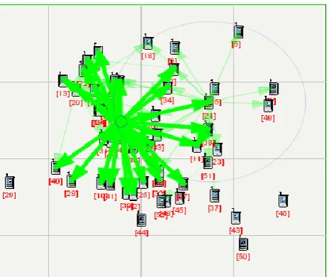
randomly deployed 52 nodes in the deployment area. In the second scenario similarly CBR traffic is applied between seven source destination node pairs namely (2, 39), (12, 30), (19, 27), (23, 41), (45, 31), (55, 29) and (65, 16) respectively as shown in figure 2 over randomly deployed 72 nodes in the deployment area. In both the scenarios Random Waypoint (RWP) mobility model is considered. Table 1 gives a list of various simulation parameters. We have enhanced both security and throughput at the same reducing end-to-end delay and jitter in our proposed schemes. This can be attributed to the fact by taking only links with high SNR value we ensure reliability, increased throughput and security. Jamming and interfering signals from intruder or malicious nodes lowers a link’s SNR ratio and provides a good indication about its reliability and security.
Figure 1. Network scenario comprising of 52 mobile nodes and 7 different source - destination traffic pairs.
Figure 2. Network scenario comprising of 72 mobile nodes and 7 different sources - destination traffic pairs.
Table 1. Simulation Parameters
Parameter Value
Area 1500m X 1500m
Data Rate 2 Mbps
Packet Size 512 bytes.
Mobility Model Random-Way Point
Physical Layer
Radio Type IEEE 802.11b,Abstract
MAC Protocol IEEE 802.11
Antenna Model Omni directional
Temperature 290 K
SNR Threshold 10 dB
4.1. Performance Metric
We have considered the network metrics like throughput, end-to-end delay and jitter. In our simulation we have measured the above metrics for original OLSR-INRIA, DSR, ZRP and also for SOLSR-INRIA, SDSR, and SZRP under both the network scenarios and have compared the results.
4.1.1. Throughput
We have measured end to end throughput in Kbits/sec for each source destination pair over both the network scenarios. A high individual and average throughput is observed in all the cases by the modified protocols. The result obtained can be attributed to the fact that due to the selection of the path having highest SNR value the impact of interference and jamming signals are less and path bandwidth is increased which is reflected as higher throughput that is desirable for almost every envisaged application of MANET. The results are shown in Table 2 and Fig 3. A considerable improvement in average throughput is observed in both the scenario for all routing protocol.
In case of SOLSR-INRIA the throughput is increased by 34% for the first scenario and 89% for the second scenario. In case of SDSR the throughput is increased by 4-5% for both the scenario. As well as for SZRP the throughput is increased 5 to 6 times in comparison to other two protocols.
Table 2. Comparison of Average Throughput.
Throughput (In KB/Sec)
52 Nodes Scenario
72 Nodes Scenario
OLSR-INRIA 12.70 16.12
SOLSR-INRIA 17.10 30.50
DSR 29.50 29.20
SDSR 30.70 30.80
ZRP 04.10 06.20
SZRP 27.70 30.10
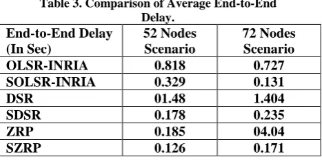
4.1.2. End-to-End Delay
[image:4.595.58.290.237.432.2] [image:4.595.57.290.495.693.2]bandwidth resulting in lower queuing delay at the intermediate nodes. So the overall end to end delay is reduced which is an important QoS in applications such as video streaming, live telecast and others. The results are shown in table 3. Fig 4 and fig 6 shows the end to end delay for scenario 1 and scenario 2 as well. A significant reduction in average end to end delay is observed which makes this type of modified protocol suitable for video streaming operations.
[image:5.595.55.289.227.349.2]In case of SOLSR-INRIA the End-to-End Delay is decreased by 59% for the first scenario and 81% for the second scenario. In case of SDSR the End-to-End Delay is decreased by 87% for the first scenario and 83% for the second scenario. As well as for SZRP the End-to-End Delay is decreased by 32% for the first scenario and 95% for the second scenario.
Table 3. Comparison of Average End-to-End Delay.
End-to-End Delay (In Sec)
52 Nodes Scenario
72 Nodes Scenario
OLSR-INRIA 0.818 0.727
SOLSR-INRIA 0.329 0.131
DSR 01.48 1.404
SDSR 0.178 0.235
ZRP 0.185 04.04
SZRP 0.126 0.171
4.1.3. Jitter
Jitter measures the variability of delay of packets in the given stream, which is an important property for many applications (for example, streaming real-time applications). Ideally, packets should be delivered in a perfectly periodic fashion; however, even if the source
generates an evenly spaced stream, unavoidable jitter is introduced by the network due to the variable queuing and propagation delays, and packets arrive at the destination with a wide range of inter-arrival times. The jitter increases at switches along the path of a connection due to many factors, such as conflicts with other packets wishing to use the same links, and nondeterministic propagation delay in the data-link layer. In our modified protocol average jitter decreases for SOLSR-INRIA, SDSR and as well as for SZRP. The results are shown in table 4. Fig 5.
[image:5.595.310.541.241.346.2]In case of SOLSR-INRIA the Jitter is decreased by 52% for the first scenario and 67% for the second scenario. In case of SDSR the Jitter is decreased by 84% for the first scenario and 75% for the second scenario. As well as for SZRP the Jitter is decreased by 68% for the first scenario and 76% for the second scenario.
Table 4. Comparison of Average Jitter. Jitter
(In Sec)
52 Nodes Scenario
72 Nodes Scenario
OLSR-INRIA 0.124 0.112
SOLSR-INRIA 0.059 0.036
DSR 0.497 0.493
SDSR 0.077 0.120
ZRP 0.067 0.264
SZRP 0.021 0.061
[image:5.595.55.542.424.618.2]The parameters throughput, end-to-end delay and jitter are the major QoS determining the performance of a MANET. Multimedia related applications require enhanced throughput and reduced end-to-end delay whereas real time applications needs to have low jitter. These parameters are also interrelated.
Figure 3.Comparision of Throughputs for OLSR-INRIA & SOLSR-INRIA, DSR & SDSR and ZRP & SZRP for 52 & 72 Nodes.
0 20
40 12.7 17.1 29.5 30.7
4.1
27.7
16.12 30.5 29.2 30.8
6.2
30.1
T
hrough
pu
t
(K
B
/Sec)
Protocols
Comparision of Throughputs for OLSR-INRIA & SOLSR-INRIA, DSR &
SDSR and ZRP & SZRP for 52 & 72 Nodes
1st Scenario with 52 Nodes
Figure 4. Comparison of End-to-End Delay for OLSR-INRIA & SOLSR-INRIA, DSR & SDSR and ZRP & SZRP for 52 & 72 Nodes.
Figure 5.Comparision of Jitter for OLSR-INRIA & SOLSR-INRIA, DSR & SDSR and ZRP & SZRP for 52 & 72 Nodes.
5. CONCLUSION AND FUTURE WORK
From the simulation results it can be concluded that for SOLSR-INRIA, SDSR and SZRP average throughput increases while average end-to-end delay and jitter decreases considerably as compared to OLSR-INRIA, DSR and ZRP in both the scenarios. The modified protocols avoid malicious nodes and noisy links by choosing the highest SNR path which increases overall network reliability. Random Waypoint (RWP) mobility model is considered as it encompasses most of the envisaged application areas of MANETs. We have extensively simulated our methods using QualNet 4.5 [11] network simulator. As a future work other mobility models and data traffic might be considered. Intrusion detection methods may be incorporated in the route discovery phase of OLSR-INRIA, DSR and ZRP for detection of malicious nodes to enhance network reliability.
6. REFERENCES
[1] T.H Clausen, G.Hansen, L.Christensen, G. Behrmann, “ The Optimised Link State Routing Protocol Evaluation Through Experiments and Simulations”, Proceedings of IEEE Symposium on Wireless Personal Mobile Communications, 2001, September 2001.
[2] D.B Johnson, D.A. Maltz, “Dynamic Source Routing in Ad Hoc Wireless Networks”, Mobile Computing, Kluwer Academic Publishers, 1996, vol. 353, pp. 153-181.
[3] D. Sivakumar, B. Suseela, R. Varadharajan, “A Survey of Routing Algorithms for MANET”, IEEE International Conference on Advances in Engineering, Science and Management (ICAESM), March 30-31, 2012, pp. 625-640. Available in IEEE Explore.
[4] V.Jha, K. Khetarpal, M.Sharma, “A Survey of Nature inspired Routing Algorithms for MANETs”, IEEE 3rd International Conference on Electronics, Computing Technology (ICECT), April 8-10, 2011, pp. 1-4. Available in IEEE Explore.
0 2 4 6
0.818 0.329 1.48
0.178 0.185
0.126 0.727 0.131 1.404
0.235 4.04
0.171
A
vg.
E
nd
-to
-E
nd
D
el
ay
(In
Sec)
Protocols
Comparision of End-to-End Delays for OLSR-INRIA & SOLSR-INRIA, DSR &
SDSR and ZRP & SZRP for 52 & 72 Nodes
1st Scenario with 52 Nodes
2nd Scenario with 72 Nodes
0 0.2 0.4 0.6
0.124
0.059
0.497
0.077
0.067
0.021 0.112
0.036 0.493
0.012
0.264
0.061
A
vg.
Ji
tt
er
(
In
Sec)
protocols
Comparision of Jitter for OLSR-INRIA & SOLSR-INRIA, DSR & SDSR and
ZRP & SZRP for 52 & 72 Nodes
1st Scenario with 52 Nodes
[image:6.595.51.541.304.513.2][5] S.Weber, J.G Andrews, N. Jindal, “An Overview of Transmission Capacity of Wireless Networks”, IEEE Transactions on Communication, vol. 58, Issue. 12, 2010, pp. 3593-3604.
[6] Royer E M, Toh C K, “A review of current routing protocols for Adhoc mobile wireless networks” IEEE Journal of Personal Communications, Dec. 2006, vol. 6(2), pp. 46- 55.
[7] Z.J Haas, “The Routing Algorithm for the Reconfigurable Wireless Networks”, Proceedings of ICUPC 1997, vol. 2, pp. 562-566, October 1997.
[8] P. Nand, and S.C. Sharma, “Performance study of Broadcast based Mobile Ad hoc Routing Protocols AODV, DSR and DYMO”, Proc. International Journal of Security and Its Applications, Vol. 5, No. 1, January, 2011, pp. 53-64.
[9] D.B. Johnson, D.A. Maltz and J. Borch, “DSR: The Dynamic Source Routing Protocol for Multi-Hop Wireless Ad Hoc Networks”, Computer Science Department Carnegie Mellon University Pittsburgh,
PA15213-3891, Dec. 2009.
http://www.monarch.cs.cmu.edu.
[10] J. Liy, H. Kameday and Y. Panz, “Study on Dynamic Source Routing Protocols for MANET”, Institute of Information Science and Electronics, University of Tsukuba, Japan. Department of CS, Georgia State University. University Plaza, Atlanta, GA 30303, USA.
[11] Scalable Networks Technologies: Qualnet Simulator 4.5 http://www.scalable-networks.com .
[12] Saurav Ghosh, Chinmoy Ghorai, “ Evaluating the Performance of Modified DSR in Presence of Noisy Links using QUALNET Network Simulator in MANET”, Proc. International Journal of Smart Sensors and Ad Hoc Networks (IJSSAN) ISSN No. 2248-9738 Volume-1, Issue-2, 2011, pp. 35-40.
[13] Arun Kumar B. R., Lokanatha C. Reddy, Prakash S. Hiremath, “Performance Comparison of Wireless Mobile Ad-Hoc Network Routing Protocols” International
Journal of Computer Science and Network Security, VOL.8 No.6, June 2008, pp.337-343.
[14] G.R Vijayavani, G. Prema, “Performance Comparison of MANET Routing Protocols with Mobility Model derived based on Realistic Mobility Pattern of Mobile Nodes”, IEEE Conference on Advanced Communication, Control and Computing Technologies (ICACCCT) 2012, pp. 32-36. Available in IEEE Explore.
[15] Zygmunt J. Haas and Marc R. Pearlman and Prince Samar, “The Intrazone Routing Protocol (IARP) for Ad Hoc Networks”, Draft-ietf-manet-zone- iarp-01.txt, June 2001.
[16] Zygmunt J. Haas and Marc R. Pearlman and Prince Samar, “The Interzone Routing Protocol (IERP) for Ad Hoc Networks”, Draft-ietf-manet-zone- ierp 02.txt July 2002.
[17]. M.N. SreeRangaRaju and Dr. Jitendranath Mungara, “Optimized ZRP for MANETs and its Applications”, proceedings of International Journal of Wireless & Mobile Networks (IJWMN) Vol. 3, No. 3, June 2011.