© 2017, IRJET | Impact Factor value: 5.181 | ISO 9001:2008 Certified Journal
| Page 1843
Performance based evaluation of conventional RC framed structure
compared with multistorey Flat slab
Priyanka Desai
1, Basavaraj Gudadappanavar
21
P.G student, Dept. of Civil Engineering, SDMCET Dharwad, Karnataka, India
2Assistant Professor, SDMCET Dharwad, Karnataka, India
---***---
Abstract - As we move towards the implementation of Performance Based Engineering philosophies in seismic design of Civil Engineering structures, new seismic design provisions require Structural Engineers to perform both linear and nonlinear analysis for the design of structures. In the present work 11 storey building of RC framed conventional slab and Flat slab were modeled, and also models with Shear wall and without shear wall have been considered. Equivalent static and response spectrum methods are carried out as per IS: 1893 (Part 1) -2002 using ETABS. Seismic performance is assessed by pushover analysis as per ATC-40 guidelines for earthquake zone III in India. This work highlights the accuracy of Push over analysis with the most commonly adopted Response Spectrum Analysis and Equivalent Static Analysis. A comparison of multistorey flat slab and RC conventional slab is also studied.
Key Words: Equivalent static method, Response spectrum method, Pushover analysis, Shear wall, ETAB’s.
1. INTRODUCTION
In the earlier days the structures were designed for loads in the vertical direction and slowly moved towards the horizontal loads. Nowadays the trend has changed towards taller and slender buildings the usage of flat slabs is increasing. So it is becoming essential to take together the effects of horizontal load on the building in the designing itself. The structural engineers are facing the difficulty of designing the building for seismic loads, loads from heavy winds, impact and blast loading.
The flat slab construction has been on the rise because of certain advantages of the system over normal beam and column construction. The system provides easy form working, flexibility and lessens the time for construction. Also the height of the building can be lessened. It provides ample space and has aesthetic appearance. However some issues have to be tackled in this system of construction i.e. there is higher displacement in transverse direction because of no RCC wall resisting shear and absence of deep beam which accounts to lesser stiffness in the transverse direction. There would be much deformation which would cause damage to members which are not structural members even in the case of less intensity earthquake. When the building is imposed with seismic load, there
would be moments produced which are unbalanced and which in turn would cause large shear stress in the flat slab. This system would be sensitive enough for the lowering of stiffness which is a result of cracks happening due to service thermal loads, shrinkage, horizontal and other loads. So we can propose flat slab construction which would be acting as member which is carrying loads in vertical direction along with shear walls which would be having horizontal capacity in case of large seismic vulnerable places.
Shear walls would be a very good means for many storied RCC buildings and flat slab buildings. The nature of the buildings during seismic loading would depend on stiffness of the structure, the weight of the structure and both directional strength. The shear walls which are built up of RCC and are included in the structure as normal walls and having capacity to resist horizontal and vertical loads. These walls can resist the seismic loads. These walls are provided both in low rise and high rise buildings to resist the collapse of the building during seismic action.
2.1 OBJECTIVES OF PRESENT STUDY
To analyze seismic performance of multistory flat slab with the conventional RC
Frame on sloping and plain grounds.
To study the behavior 0f structure under equivalent static and resp0nse spectrum meth0d.
To study the behavior of structure under Non-linear static analysis (Pushover).
T0 suggest the shear wall location for the building.
To compare the RC structure and flat slabs.
2.2. METHODOLOGY
© 2017, IRJET | Impact Factor value: 5.181 | ISO 9001:2008 Certified Journal
| Page 1844
Nearly 18 models were done for suggesting the shear wall location to know the exact location to be provided in the model. A comparison of conventional RC frame structure with the multistory flat slab is done.
3 DESCRIPTION OF MODELING
A 11 storey building having each storey height 3.6 meters is modeled. The buildings are fixed at the base. In this project including the ground storey each storey heights of buildings are same. The dimensions of the buildings considered along X & Y directions are 25m by 25m in plain. It has 5 at 5m bay along X direction and 5 at 5m bay along Y direction. Thus 18 models are modeled out of which four of plain ground and five of sloping ground which are of RC structures and similarly with the flat slab structures.
The buildings are modeled with and without shear walls and subjected to seismic action and analyzed for the various structural analyses using ETABS.
3.1.1 Sectional Properties:
For RC Structure
1. Floor to floor height = 3.6m 2. Size of beams = (350X700)mm 3. Size of columns = (350X1000)mm 4. Slab thickness = 150mm
For Flat Slab structure
1. Floor to floor height = 3.6m 2. Size of column = (350X1000)mm 3. Slab thickness = 350mm
3.1.2 Material Properties:
1. Characteristic strength, fck= 25MPa
2. Yield stress for steel, Fy= 500MPa
3. Unit weight of concrete = 25kN/m3
4. Modulus of Elasticity of concrete, Ec = 25000 Mpa
5. Modulus of elasticity of steel, Es= 2x10⁵N/m2
3.1.3 Load Considered:
1. Gravity Load:
Dead load = 5.25 kN
Live Load = 3 kN/m2
2. Lateral Loads:
Seismic zones of values zone 3 are considered. i. Seismic zone = Z = 3
ii. Importance factor = I = 1
iii. Response reduction factor = R = 5 iv. Soil type = Medium soil
v. Total height of the building = 25m
4. RESULT AND DISCUSSION
Results from the analysis are storey stiffness, storey displacement, base shear and time period are known from both static and response spectrum analysis for both conventional RC and flat slab buildings are known. The main difference can be found between the storey stiffness, storey displacement, time period and base shear. Results of Pushover analysis are also put.
4.1NATURAL TIME PERI0D
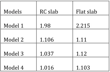
[image:2.612.357.544.458.581.2]The time required for undamped system to complete one cycle of free vibration is the natural period of vibration of the system in units of seconds. Table shows different values of natural time period for RC conventional slab and flat slab building. Graphs for variation of natural time period for RC conventional and flat slab budilng for 11 storey building is shown.
Table -1: Shows Results of Natural Time Period for RC conventional slab and Flat slab
Models RC slab Flat slab
Model 1 1.98 2.215
Model 2 1.106 1.11
Model 3 1.037 1.12
© 2017, IRJET | Impact Factor value: 5.181 | ISO 9001:2008 Certified Journal
| Page 1845
Fig-1: Natural time period for RC conventional slab andflat slab
From the graph we conclude that, In comparision with RC conventional building to Flat slab building, the time period is less for conventional building than flat slab building. The natural time period increases as the height of the building increases, i.e irrespective of buildings.
4.2 BASE SHEAR
Base shear is the estimated of maximum expected lateral force that will occur due to seismic ground motion at the base of a structure. The total lateral force (Vb) can be calculated from the formula.
[image:3.612.318.583.79.335.2]Vb= Ah W
Table –2: shows values of base shear for different models include with shear wall and without shear wall. From the analysis we can say that, Base shear for RC Conventional is less than Flat slab.
For RC Conventional Slab
Base Shear
(Vb)
Equivalent Static Method
(kN)
Response Spectrum Method (kN)
For plain groun d
Longitudin al
direction
Transver se direction
Longitudin al
direction
Transver se direction
M 1 2984 2984 1297 961
M 2 3215 3215 2321 2009
M 3 3216 3216 1912 1743
M 4 3216 3216 1980 1775 For Flat Slab
Base Shear
(Vb)
Equivalent Static Method
(kN)
Response Spectrum Method (kN)
For plain groun d
Longitudin al
direction
Transver se direction
Longitudin al
direction
Transver se direction
M 1 3577 3577 1421 1041 M 2 3808 3808 2409 2161 M 3 3808 3808 2124 1945 M 4 3808 3808 2173 1983
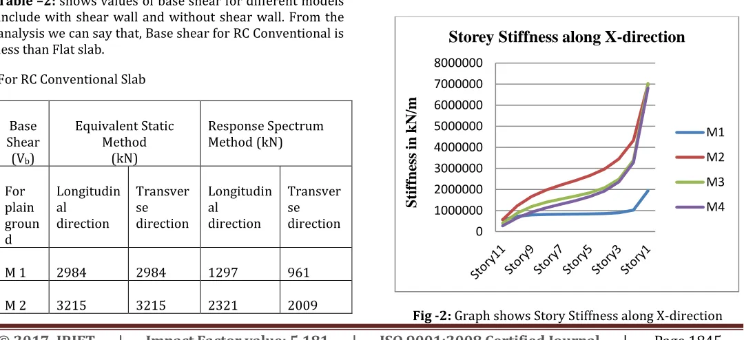
4.3 STOREY STIFFNESS
“The lateral stiffness of storey is generally defined as the ratio of story shear to story displacement”. Structures have vertical stiffness or strength variations for many reasons thus change in story stiffness results change in strength for the same story.
Results of storey stiffness from Equivalent static method for different models with graphs
For RC Conventional slab
Fig -2: Graph shows Story Stiffness along X-direction
0
0.5
1
1.5
2
2.5
M1M2M3M4
RC SLAB
FLAT
SLAB
0 1000000 2000000 3000000 4000000 5000000 6000000 7000000 8000000
Sti
ff
nes
s
in
kN
/m
Storey Stiffness along X-direction
M1
M2
M3
[image:3.612.38.578.489.736.2]© 2017, IRJET | Impact Factor value: 5.181 | ISO 9001:2008 Certified Journal
| Page 1846
From the graph, Story Stiffness dcreases with increase in the height, as it goes in increase with height stiffness goes on decreasing. Storey stiffness for model without shear wall is very less compared with models having shear wall in X- direction. Model 2 is having high stiffness compared to other models having shear wall. There is very large decrement from storey 1 to storey 3 and it goes on decreasing upto story 11. As we know that lesser the stiffness of building lesser will be the stability of building, this can easily be known from the above graph.
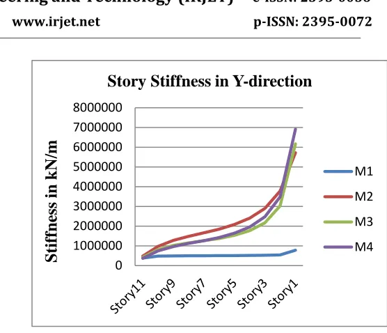
Fig -3: Graph shows Story Stiffness along Y-direction
From the graph, Story Stiffness dcreases with increase in the storey height. Storey stiffness for model without shear wall is very less compared with models having shear wall in Y- direction. There is very large decrement from storey 1 to storey 3 and it goes on decreasing upto story 11. Model 4 is having higher stiffness than other models.
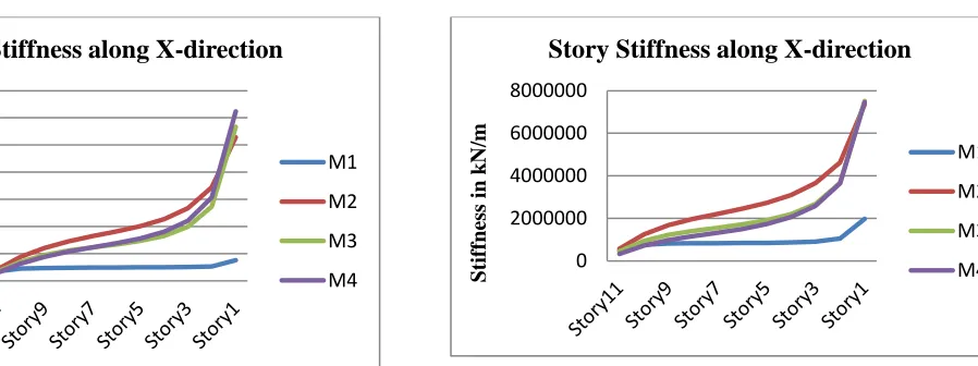
[image:4.612.323.581.185.358.2]For Flat slab
Fig- 4: Graph shows Story Stiffness along X-direction
From the graph, Story Stiffness dcreases with increase in the height, as it goes in increase with height stiffness goes on decreasing. Storey stiffness for model without shear wall is very less compared with models having shear wall in X- direction. There is very large decrement from storey 1 to storey 3 and it goes on decreasing upto story 11. Model 4 is having higher stiffness than other models.
Fig-5: Graph shows Story Stiffness along Y-direction
From the graph, Story Stiffness dcreases with increase in the storey height. Storey stiffness for model without shear wall is very less compared with models having shear wall in Y- direction. There is very large decrement from storey 1 to storey 3 and it goes on decreasing upto story 11. Model 4 is having higher stiffness than other models.
Results of storey stiffness from Response Spectrum method for different models with graphs
For RC Conventional slab
Fig -6: Graph shows Story Stiffness along X-direction
0 1000000 2000000 3000000 4000000 5000000 6000000 7000000
Stif
fnes
s
in k
N/m
Story Stiffness along Y-direction
M1
M2
M3
M4
0 1000000 2000000 3000000 4000000 5000000 6000000 7000000
S
tif
fn
ess
in
k
N/m
Story Stiffness along X-direction
M1
M2
M3
M4
0 1000000 2000000 3000000 4000000 5000000 6000000 7000000
S
tif
fn
ess
in
k
N/m
Story Stiffness along Y-direction
M1
M2
M3
M4
0 2000000 4000000 6000000 8000000
Stif
fnes
s
in k
N/m
Story Stiffness along X-direction
M1
M2
M3
[image:4.612.37.299.218.385.2] [image:4.612.117.566.518.686.2]© 2017, IRJET | Impact Factor value: 5.181 | ISO 9001:2008 Certified Journal
| Page 1847
Fig –7: Graph shows Story Stiffness along Y-directionFor Flat slab
[image:5.612.35.299.77.286.2]Fig –8: Graph shows Story Stiffness along X-direction
Fig- 9: Graph shows Story Stiffness along Y-direction
4.4 STOREY DISPLACEMENT
Story displacement is the total displacement of ith storey with respect to ground. Following Graphs shows Maximum Story Displacement for different models.
Results of storey displacement from Equivalent static method for different models with graphs
For RC Conventional slab
Fig –10: Graph shows Story displacement along X-direction
0 1000000 2000000 3000000 4000000 5000000 6000000 7000000
Stif
fnes
s
in k
N/m
Story Stiffness along Y-direction
M1
M2
M3
M4
0 1000000 2000000 3000000 4000000 5000000 6000000 7000000 8000000
S
tif
fn
ess
in
k
N/m
Story Stiffness along X-direction
M1
M2
M3
M4
0 1000000 2000000 3000000 4000000 5000000 6000000 7000000 8000000
S
tif
fn
ess
in
k
N/m
Story Stiffness in Y-direction
M1
M2
M3
M4
0 5 10 15 20 25 30
Sto
ry
11
Sto
ry
10
Story
9
Sto
ry
8
Sto
ry
7
Sto
ry
6
Sto
ry
5
Sto
ry
4
Sto
ry
3
Sto
ry
2
Sto
ry
1
Disp
lace
m
en
t
in
m
m
Storey Displacement along X-direction
M1
M2
M3
[image:5.612.39.295.338.534.2] [image:5.612.318.579.432.629.2]© 2017, IRJET | Impact Factor value: 5.181 | ISO 9001:2008 Certified Journal
| Page 1848
Fig- 11: Graph shows Story displacement along Y-directionFrom the graph, Storey displacement increases with increase in the storey height for all the models with shear wall and without shear wall. Model 1 has more
displacement when compared with other models. Model 2 i.e shear wall located at the centre is having very less displacement compared to other models. Thus it gives higher resistance compared to other models.
For Flat slab
Fig- 12: Graph shows Story displacement along X-direction
Fig- 13: Graph shows Story displacement along Y-direction
From the graph, Storey displacement increases with increase in the storey height for all the models with shear wall and without shear wall. Model 1 has more displacement when compared with other models. Model 2 i.e shear wall located at the centre is having very less displacement compared to other models. Thus it gives higher resistance compared to other models.
Results of storey stiffness from Response Spectrum method for different models with graphs
For RC Conventional slab
Fig- 14: Graph shows Story displacement along X-direction
0 10 20 30 40 50 60
Disp
lace
m
en
t
in
m
m
Storey Displacement along
Y-direction
M1 M2 M3 M4 0 10 20 30 40 50 60 Sto ry 11 Sto ry 10 Sto ry 9 Sto ry 8 Sto ry 7 Sto ry 6 Sto ry 5 Sto ry 4 Sto ry 3 Sto ry 2 Sto ry 1Disp
lace
m
en
t
in
m
m
Storey Displacement along X-direction
M1 M2 M3 M4 0 10 20 30 40 50 60 Sto ry 11 Story 10 Sto ry 9 Sto ry 8 Story 7 Sto ry 6 Sto ry 5 Sto ry 4 Sto ry 3 Sto ry 2 Sto ry 1
D
isp
lac
em
ent
in
m
m
Storey Displacement along Y-direction
M1 M2 M3 M4 0 2 4 6 8 10 12 Story 11 Sto ry 10 Sto ry 9 Sto ry 8 Sto ry 7 Sto ry 6 Sto ry 5 Sto ry 4 Sto ry 3 Sto ry 2 Sto ry 1
D
isp
lac
em
ent
in
m
m
Storey Displacement in X-direction
M1
M2
M3
© 2017, IRJET | Impact Factor value: 5.181 | ISO 9001:2008 Certified Journal
| Page 1849
Fig- 15: Graph shows Story displacement along Y-directionFrom the graph, Storey displacement increases with increase in the storey height for all the models with shear wall and without shear wall. Model 1 has more displacement when compared with other models. Model 2 i.e shear wall located at the centre is having very less displacement compared to other models. Thus it gives higher resistance compared to other models.
For Flat slab
Fig- 16: Graph shows Story displacement along X-direction
Fig- 17: Graph shows Story displacement along Y-direction
From the graph, Storey displacement increases with increase in the storey height for all the models with shear wall and without shear wall. Model 1 has more displacement when compared with other models. Model 2 i.e shear wall located at the centre is having very less displacement compared to other models. Thus it gives higher resistance compared to other models.
CONCLUSIONS
1) From the results it is evident that Natural time period is more for flat slab than for the conventional building.
2) From the results we can say that, Base shear for Flat Slab is more than that of RC Conventional Slab.
3) Storey stiffness at the bottom storey is more compared with the top storey, thus as the storey height increases stiffness value decreases gradually.
4) Story displacement increases as there is an increase in storey height for all the models irrespective of all the conditions, such as model having with shear wall and without shear wall.
5) Structure without shear wall is having more displacement and less stiffness compared with structure having shear wall.
6) With comparision of both methods Response spectrum analysis has given more accuracy than Equivalent static method.
0 2 4 6 8 10 12 14 16 Sto ry 11 Sto ry 10 Sto ry 9 Sto ry 8 Sto ry 7 Sto ry 6 Sto ry 5 Sto ry 4 Sto ry 3 Sto ry 2 Sto ry 1
Disp
lace
m
en
t
in
m
m
Storey Displacement along Y-direction
M1 M2 M3 M4 0 2 4 6 8 10 12 14 16 Sto ry 11 Sto ry 10 Sto ry 9 Sto ry 8 Sto ry 7 Sto ry 6 Sto ry 5 Sto ry 4 Sto ry 3 Sto ry 2 Sto ry 1
Disp
lace
m
en
t
in
m
m
Storey Displacement X-direction
M1 M2 M3 M4 0 2 4 6 8 10 12 14 16 Sto ry 11 Sto ry 10 Sto ry 9 Sto ry 8 Sto ry 7 Sto ry 6 Sto ry 5 Sto ry 4 Sto ry 3 Sto ry 2 Sto ry 1
D
isp
lac
em
ent
in
m
m
Storey Displacement along Y-direction
M1
M2
M3
© 2017, IRJET | Impact Factor value: 5.181 | ISO 9001:2008 Certified Journal
| Page 1850
7) For more accurate results of structure Pushover analysis is performed as it gives structural accurancy compared with the other two methods.
8) Performance point of the RC conventional without shear wall and flat slab without shear wall were observed before the collapse of the building, and its concluded that building is safe.
9) Similarly for both the models having shear wall at centre are observed before the collapase of the building, and hence its building is safe.
REFERENCES
[1] Prof. K S Sable, Er. V A Ghodechor, Prof. S B Kandekar, Comparative Study of Seismic Behavior of Multistory Flat Slab and Conventional Reinforced Concrete Framed Structures, Volume 2, Issue 3, June 2012.
[2] Dr. M Rame Gowda1, Techi Tata2, study of seismic behaviour of buildings with flat slab, Volume: 03 Issue: 09 | Sep-2016.
[3] K. G. Patwari1, L. G. Kalurkar2, Shear wall Locations with Flat Slab and its Effect on Structure Subjected to Seismic Effect for Multistorey Building, Volume 6 Issue No. 8
[4] Likhitharadhya Y R, Praveen J V, Sanjith J, Ranjith A, Seismic Analysis of Multi-Storey Building Resting On Flat Ground and Sloping Ground, Vol. 5, Issue 6, June 2016.
[5] S.D.Uttekar, C.R.Nayak, A Review on Seismic Response of RC Building on Sloping Ground, Volume No.5 Issue: Special 3, pp: 701-704.
[6] P. B. Oni, Dr. S. B.Vanakudre, Performance Based Evaluation of Shear Walled RCC Building by Pushover Analysis, Vol. 3, Issue. 4, Jul - Aug. 2013.
[7] K.Soni Priya, T. Durgabhavani, “Nonlinear pushover analysis of flat slab building using SAP2000”.
[8] IS: 1893 (part 1) 2002 – Indian standard – “ Crieteria for earthquake resistant design of structures”, Bureau of Indian standards, New Delhi.
[9] IS: 875 (part 1) 1987, “Code of practice for design loads (other than earthquake) for buildings and structures”, Bureau of Indian standard, New Delhi.
[10] IS 875 (part 2) 1987, “Code for practice for design loads (other than earthquake) for buildings and structures, imposed loads.