© 2018, IRJET | Impact Factor value: 6.171 | ISO 9001:2008 Certified Journal | Page 4946
EFFECT OF FLOATING COLUMN ON THE SEISMIC BEHAVIOUR OF A
MULTISTORIED BUILDING
Sreevidya M G
1, Neethu Joseph
2, Tilba Thomas
31MTech Student, Department of Civil Engineering, St. Joseph’s College of Engineering and Technology,
Palai, Kerala, India
2,3 Assistant professor, Department of Civil Engineering, St. Joseph’s College of Engineering and Technology,
Palai, Kerala, India
---***---Abstract -
Now a day’s many multistoried buildings areconstructed by providing floating column for aesthetic purposes and for getting more space at parking areas at the basement floor. But, the chances for such buildings to get damaged during earthquake are high as compared to normal building. Providing floating columns may satisfy some of the functional requirements, but structural behaviour changes suddenly due to the provision of floating columns. In this paper, seismic analysis is done for a multistoried building with and without floating columns. Also, bracings (X type, diagonal and inverted V) are included in floating column buildings to find out the best one among them. Analysis was performed to analyze and observe the behaviour, performance and response of a (G+10) storied building in seismic zone III. Equivalent static analysis is carried out for all the models. The structural response of the building models with respect to time period, base shear and storey displacements are compared for all the models. The analysis was done using the structural software SAP 2000v19.
Key Words: Floating column, Retrofitting, Bracings, Equivalent Static Analysis, Base Shear, Time period
1. INTRODUCTION
When RCC multistoried buildings are constructed, it is important to make the structure safe against lateral load caused by earthquake. Earthquakes causes several damages, even the collapse of buildings. Therefore, seismic retrofitting or strengthening of building structures is one of the most important aspects for mitigating seismic hazards especially in earthquake prone areas.
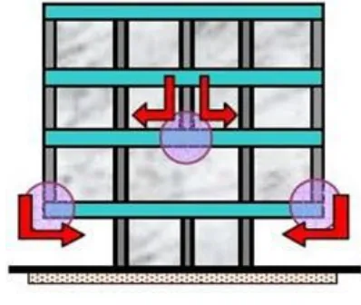
1.1 Floating Column
A column is a vertical compression member used to transfer load to the ground. Floating column is a vertical member which at its lower level resting on a beam and doesn’t have a foundation. Floating columns are otherwise called hanging columns. Floating column acts as a concentrated load on the beam on which it rests and this beam transfers the load to the columns below it. This means that the beam which support the floating column acts as the foundation. The beam which supports the floating column is called transfer beam. Floating columns are extensively used in multistoried buildings for residential, industrial and commercial purposes. Floating columns are provided, especially above the base floor so that added open space is accessible for assembly hall or parking purposes.
Fig -1: Hanging or floating columns
1.2 Objectives of present study
To study the effect of floating column under earthquake excitations using SAP2000v19 in seismic zone III.
To check whether buildings with floating column shows equal or more resistance than normal buildings if various retrofitting techniques are provided.
To compare the base shear, time period and storey displacement of different models.
3. STRUCTURAL MODELING OF THE BUILDING
For this study, a (G+10) RC building with 3metre height for each floor is considered. The building is considered to be situated in seismic zone III. The building is designed as per Indian Code of Practice for Seismic Resistant Design of Buildings. The load cases are considered as per 1S 1893:2002. The buildings were modelled and analysed using software SAP2000v19. Table1 shows the details and load considerations of the building model.
Table -1: Details of building model
[image:1.595.331.530.223.391.2]© 2018, IRJET | Impact Factor value: 6.171 | ISO 9001:2008 Certified Journal | Page 4947 Height of each floor 3 metre
Grade of concrete M30
Grade of steel Fe 500
Type of joint Fixed
Size of beams 200mm × 450mm
Size of columns 300mm × 600mm Depth of slab RC slab of 150mm thick Size of bracings 150mm × 150mm × 12mm Seismic zone III, Z=0.16
Type of soil Medium; Type-II Response reduction factor 5
Importance factor 1
Damping factor 5%
Dead load 1 kN/m²
Live load 3 kN/m²
3.1 Load combinations
▪ 1.5 DL + 1.5 LL
▪ 1.2 DL + 1.2 LL+1.2 EX
▪ 1.2 DL + 1.2 LL – 1.2 EX
▪ 1.2 DL +1.2L.L +1.2 EY
▪ 1.2 DL + 1.2 LL – 1.2 EY
▪ 1.5 DL +1.5 EX
▪ 1.5 DL – 1.5 EX
▪ 1.5 DL + 1.5 EY
▪ 1.5 DL – 1.5 EY
▪ 0.9 DL+1.5 EX
▪ 0.9 DL+1.5EY
▪ 0.9DL-1.5EX
▪ 0.9DL-1.5EY
3.2 Modelling
Fig -2: Typical beam column layout of the building
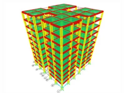
Model-1: Bare frame without floating column
Here, a (G+10) building without floating column is considered with dimensions of beams as 200mm × 450mm and size of columns as 300mm × 600mm. The size of beams and columns are kept same for the entire building model.
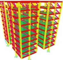
Model-2: Bare frame with floating column at edges
In this model, floating column is provided at the edges. The dimensions of beams and columns are same as the above.
Model-3: Floating column at edges, with X bracings
Here, in this model, X bracings are provided on floating column building.
Model-4: Floating column at edges, with diagonal bracings
Here, in this model, diagonal bracings are provided on floating column building.
Model-5: Floating column at edges, with inverted V bracings
Here, in this model, inverted V bracings are provided on floating column building.
Fig -3:Bare frame without floating column(Model 1)
[image:2.595.30.296.72.324.2] [image:2.595.333.532.406.555.2] [image:2.595.364.471.595.737.2]© 2018, IRJET | Impact Factor value: 6.171 | ISO 9001:2008 Certified Journal | Page 4948 Fig -5: Floating column at edges,with X bracings (Model 3)
[image:3.595.305.565.93.477.2]Fig -6: Floating column at edges, with diagonal bracings (Model 4 )
Fig -7: Floating column at edges, with inverted V bracings (Model 5)
3. RESULTS AND DISCUSSIONS
3.1 Storey Displacement (mm)
[image:3.595.105.215.280.385.2]Storey displacement is the lateral movement of the structure caused by lateral force. The deflected shape of a structure is the powerful and clearly visible point of comparison of any structure. It gives a better idea of the structure under consideration. The storey wise displacement for different models are given in table 2.
Table -2: Displacement for different models
Storey
number Model 1 Model 2 Model 3 Model 4 Model 5
Base 0 0 0 0 0
Storey 1 0.6 0.8 1.1 1 1 Storey 2 1.7 2 1.8 2 1.8 Storey 3 3 3.3 2.6 2.9 2.6 Storey 4 4.2 4.6 3.3 3.8 3.5 Storey 5 5.4 5.9 4.1 4.6 4.3 Storey 6 6.5 7.1 4.9 5.5 5.1 Storey 7 7.5 8.2 5.6 6.3 5.8 Storey 8 8.3 9.2 6.3 7 6.5 Storey 9 8.9 10 6.9 7.7 7.2 Storey 10 9.4 10.4 7.4 8.2 7.7
Chart -1: Storey wise displacement for different models
When bare frame with and without floating column are considered, the displacement is more for the model having floating column.
When floating column is provided at the edges, the maximum displacement value increases by almost 11%.
The, displacement value increases with increase in storey height.
Building without floating column has more displacement than floating column building with various retrofitting techniques.
Also, floating column building with X bracings show least value of displacement.
3.2 Base shear (kN)
[image:3.595.108.203.440.575.2]© 2018, IRJET | Impact Factor value: 6.171 | ISO 9001:2008 Certified Journal | Page 4949 Table -3: Base shear for different models
Models Base shear (kN)
Bare frame without floating
column(Model 1) 495.926
Bare frame with floating column at
edges (Model 2) 443.192
Floating column at edges, with X
bracings (Model 3) 646.609
Floating column at edges, with
diagonal bracings (Model 4 ) 584.581 Floating column at edges, with
inverted V bracings (Model 5) 620.842
Chart -2: Base shear for different models
Base shear has least value for bare frame with floating column provided at the edges.
When floating columns are provided at the edges, base shear reduces by 10-11%.
Floating column building with various retrofitting techniques show more base shear than bare frame without floating column.
Also, floating column building with X bracings shows more base shear.
When X bracings are provided in floating column buildings, the base shear value can be increased up to 46%.
Inverted V bracings can improve the base shear of the floating column building up to 40%.
When diagonal bracings are provided in floating column building, an increase of almost 32% in the value of base shear can be seen.
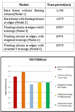
3.3 Time period (sec)
Time period of a building is the time taken by it to undergo one complete cycle of oscillation. It is an inherent property of a building controlled by its mass ‘m’ and stiffness ‘k’. Its unit is seconds. Table 4 shows the time period value for different models.
Table –4: Time Period value for different models.
Models Time period(sec)
Bare frame without floating
column(Model 1) 1.196
Bare frame with floating column
at edges (Model 2) 1.379
Floating column at edges, with X
bracings (Model 3) 0.907
Floating column at edges, with
diagonal bracings (Model 4 ) 0.974 Floating column at edges, with
inverted V bracings (Model 5) 0.979
Chart -3: Time period for different models
When building with and without floating column are considered, time period is more for the building with floating column.
When floating column is provided at the edges, time period value increases up to 15% compared to normal building.
Also, floating column building with X bracings show least value of time period.
[image:4.595.306.557.184.556.2]© 2018, IRJET | Impact Factor value: 6.171 | ISO 9001:2008 Certified Journal | Page 4950 Similarly, when inverted V bracings are used, the
time period value can be reduced up to 29%.
Also, when diagonal bracings are used, the time period value can be reduced up to 28%.
3. CONCLUSIONS
The study in this paper mainly comprises the difference between a normal column building and a floating column building with bracings and shear wall. From the present study, the following are the conclusions obtained.
Provision of floating column increases the lateral displacement of the building because when floating columns are provided, the stiffness of the building reduces and it becomes more flexible.
Provision of floating column reduces the base shear of the building because when floating column are provided, the overall weight of the structure reduces.
Floating column buildings with retrofitting techniques show more resistance than a normal building without floating column.
Building with X bracings show best behavior in all the cases.
When building with and without floating column are considered, time period is more for the building with floating column. This is due to the reduction in stiffness of the building. When stiffness of the building reduces, the building tend to oscillate more and hence increases the time period value.
Also, by providing various retrofitting techniques, time period value reduces. When retrofitting techniques are provided, the stiffness of the building increases.
REFERENCES
[1] Abhijeeth Baikerikar and Kanchan Kangali, “Seismic analysis of reinforced concrete frame with steel bracings”, International Journal of Engineering Research and Technology, Vol 3, pp 1236-1239, 2014.
[2] Adithya.M , Swathi rani K.S, Shruthi.H K and Dr.Ramesh B.R), “Study on effective bracing systems for high rise steel structures”, SSRG International Journal of Civil Engineering, Vol 2, Issue 2, pp 19-25, 2015.
[3] Amit Namdeo Chaudhari and Dr. R. S. Talikoti, “Study of seismic behavior of building with different positions and types of floating column”, International Journal of Engineering Science and Computing, Vol 7, Issue 7, pp 14056- 14063, 2017.
[4] A.P. Mundada and S.G. Sawdatkar, “Comparative seismic analysis of multistory building with and without floating column”, International Journal of Current Engineering and Technology, Vol 4, No 5, pp 3395-3400, 2014.
[5] Kavya N, Dr. K.Manjunatha and Sachin.P.Dyavappanavar, “Seismic evaluation of multistorey RC building with and without floating column”, International Research Journal of Engineering and Technology, Vol 2, Issue 6, pp 361-365, 2015.
[6] Krishnaraj R. Chavan and H.S.Jadhav , “Seismic response of r c building with different arrangement of steel bracing system”, International Journal of Engineering Research and Applications, Vol 4,Issue 7, pp 218-222, 2014.