SCA METHOD BASED ON QUALITATIVE SIMULATION
1
GUANGYAN ZHAO, 2YUFENG SUN
1
Lecturer, School of Reliability and System Engineering Beihang University, Beijing, China
1
Lecturer, Science and Technology on Reliability and Environmental Engineering Laboratory, Beijing,
China
2
Professor, School of Reliability and System Engineering Beihang University, Beijing, China
2
Professor, Science and Technology on Reliability and Environmental Engineering Laboratory, Beijing,
China
E-mail: [email protected], [email protected]
ABSTRACT
It is an effective method to use qualitative reasoning theory to realize sneak circuit analysis (SCA). The method using qualitative modeling combined with functional simulation to realize sneak circuit analysis. The qualitative models of resistive element, switch, transistor, MOS pipe, digital devices, analog devices, mechanical devices and other types of components were established and the qualitative simulation process was studied. Self-developed QSCA software (qualitative simulation-based sneak circuit analysis) is applied to analyze typical cases and verify the technical correctness. The result shows that this method could provide technical support for the system to find sneak circuit problems at the early design stage and it can also be used in the field of fault modes and effects analysis.
Keywords: Sneak Circuit Analysis (SCA), qualitative simulation, qualitative modeling
1. INTRODUCTION
Sneak circuit refers to the phenomenon of the system generating (or inhibiting) non-desired functions (or desired functions) under certain conditions. It is difficult to detect the phenomenon with conventional detection method and reliability analysis method due to its deep concealment and latency, sneak circuit will cause great harm to the system once it is stimulated, so SCA is carried out in many critical systems.
There are two main methods available for Sneak Circuit Analysis (SCA): comprehensive sneak circuit analysis method and simplified sneak circuit analysis method [1-2]. The former uses network tree generation tool to generate network forest data after the network system division and simplification, and then apply clue sheet to conduct sneak circuit analysis (SCA). This analysis method is comprehensive and complete, but requires huge workload and high costs. The latter is a simplified method that developed on the basis of comprehensive sneak circuit technology, which is based on the analysis of sneak circuit problems of key components and modules. Simplified sneak circuit analysis does not need to generate the
network tree, but employ the method of taking the key points to search critical paths instead, and then conduct Sneak Circuit Analysis (SCA) for the critical path by applying suggestive clues table about important components or combinations. Simplified SCA method employs more computer-aided analysis ingredients in data input, automatic prompt of clues and other aspects to reduce manual workload and cut down the cost of analysis. Both methods conduct analysis on the basis of clue table, but clue table can not be completed within the short-term, because it is a summary and refinement of a lot of experience and lessons of system design and testing. Hence, it is learned that Boeing Company has to spend 15 years in establishing a more comprehensive and rich clue table. On the basis of these two methods, some other analysis methods are studied now [3-6], such as analysis based on neural network, network flow simulation, topological patterns identification and so on.
behavior of devices. Thus, this paper establish a qualitative model of the circuit and effectively combine with functional model of the system for the realization of SCA so as to provide technical support for the system finding sneak circuit problems at the early design stage by reference to the idea of qualitative simulation to.
2. QUALITATIVE MODELING
Qualitative modeling is an abstract reflection of the structure and features of the problem areas to a certain extent. According to different goals and needs, there are many modeling methods and different forms of models, mainly including qualitative modeling based on amount space, qualitative physical modeling based on acausal category, modeling based on qualitative causal relationship, qualitative modeling using state transition probabilities and et al [9]. In this paper, modeling method based on qualitative causal relations was employed to simplify and abstract physical characteristics of the components, "port", "node" and "control law" are adopted to describe the impact and interaction between variables.
For the working condition of the device, the model uses State field for characterization, with numerical range [active, inactive] respectively characterizes on / off the branch circuit.
Most simple devices and complex devices can construct qualitative resistor network with 0, L (0 <L <∞), ∞ as weight values by virtue of establishing its internal network topology and variable table. 0, L (0 <L <∞), ∞ respectively represents the short circuit, load and open state of the device, which could effectively describe physical properties of the system in Sneak Circuit Analysis (SCA). This paper described qualitative modeling methods of several different types of devices.
1) Simple switch device modeling
For most of two-pin analog devices, only one qualitative parameter value can characterize working condition of the device. Such as diodes, qualitative weight value is 0 in case of positive conduction; qualitative weight is ∞ in case of reverse-blocking. The qualitative modeling of fuses, resistors and SPST switch are similar to this condition.
2) Transistor
Semiconductor transistor is one of the most commonly used analog devices in analog circuit and also an important constituent element of many
ICs. In NPN transistor, for example, NPN-type transistor equivalent weight resistor network derived from input and output switching curve of transistor is as shown in Figure 1 (a):
c
b
e (a)
D
G
S
[image:2.612.368.481.149.224.2](b)
Figure 1 Weighted resistor network diagram of the model
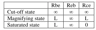
[image:2.612.341.498.324.374.2]The transistor has three different operating states, corresponding to three different combinations of device states as shown in Table 1:
Table 1 Qualitative Weight Table of Various Working States of Transistor
Rbe Reb Rce
Cut-off state ∞ ∞ ∞
Magnifying state L ∞ L
Saturated state L ∞ 0
3) MOS Transistor
N-channel enhancement-type MOS transistor is a semiconductor FET of the most common type. Controlled by threshold voltage between drain and source, FET may work in cutoff, amplification and fully conductive state.
Analysis by input-output characteristic curve of FET, weighted resistor network under amplification and fully conductive state could be expressed by the same qualitative resistance. Weighted resistor network is as shown in Figure 1 (b), corresponding qualitative resistance value is as shown in Table 2:
Table 2 Qualitative Weight Table of Various Working Status of N-channel Enhancement-type MOS Transistor
Rgs Rds
Cut-off state L ∞
Conductive state L L
4) Digital Devices
Each input and output of digital device is set as "external node" of a device, expressed by NIn ×× and NOut××, these external nodes and other devices have state variables with interactive relationship, its causal relationship shall be described by “control law” which is established by the user. Causal relationships within the device shall determine the qualitative transfer function through logic function and truth table of digital devices.
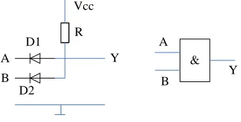
Diode and gate, for example, the circuit diagram is as shown in Figure 2 [10]:
Vcc
R D1
D2 A
B
Y &
A
[image:3.612.100.271.246.333.2]B Y
Figure 2 Diode And gate
Set three "external nodes" for this digital device, respectively NinA, NinB and NOutY. Qualitative value range of each node is [on, off], indicating different node status. Qualitative transfer function is:
NOutY =NInA·NInB
In which, "•" is qualitative “And” is equivalent to logic AND operation in logic algebra. Actual value of NinA and NInB depends on analog devices associated or external node value of other digital devices, the dependency is determined by “control law”, which is usually described in the format: If the control point status = [X], Then charged point (such as: NInA) status = [on] or [off].
5) Analog Integrated Circuits
In SCA analysis, qualitative modeling of such devices has two ways. First, based on the modeling idea of digital devices, but what is different is that qualitative value range of external node can have more options. However, interior the device, causal relationship described by performance function replaces qualitative transfer function established in compliance with logic algebra. The second is to study the function and internal structure of the device, use a qualitative abstract simple weight resistor network to simulate device behavior. When needed, internal state variables can also be established so that the description of the behavior of the device can be closer to the actual situation. The value range of external nodes is [0, L, ∞].
Normally-open relay, for example, as shown in Figure 3.
1
2
3
4
5
Figure 3 Qualitative Modeling Diagram of Normally Open Relay
When the coil is not energized, there is no current flowing through the coil, and the coil stays in non-operating state, qualitative weight value is ∞, the contact switch is engaged with normally-closed contact 3, qualitative weight between node 3 and node 4 is also 0, while qualitative weight between contact 5 and contact 4 is ∞; when coil winding is energized to work, qualitative weight is 0, the contact switch pull, contact 5 and contact 4 are conductive, qualitative weight becomes 0, weight between node 3 and node 4 also changed to ∞.
Another example, integrated operational amplifier. When ideal operational amplifier works in linear workspace, its input resistance is infinite, both inputs have "virtual short-circuit" and "virtual open-circuit” characteristics. Therefore, input current of the two inputs are 0, the net input voltage is 0; When it works in nonlinear state, differential-mode input resistance remains infinite, while the net input current is 0, but net input voltage is no longer 0. The output voltage is either positive maximum voltage or negative maximum voltage [11].
Qualitative model established on the basis of characteristics of integrated operational amplifier is shown as follows:
A1
A2
[image:3.612.367.483.557.609.2]-+
U
OFigure 4 Qualitative Modeling Diagram of Integrated Operational Amplifier
Qualitative resistance in the figure: RA1 = ∞, RA2 = ∞.
6) Mechanical device modeling in the circuit
have multiple qualitative values depending on specific circumstances of devices. These port values as the input control quantities of electrical part which affect the behavior of circuit network through "control law".
For example, engine is used as implementation device, See Figure 5.
M
Torque Control
circuit
Torque Implement
[image:4.612.97.301.188.281.2]Implementing Mechanism (gear drive mechanism drives the belt to transport materials) Implement
Figure 5 Mechanical Device Modeling Example
Physical characteristic quantity of engine is the forward/reverse rotation. The characteristic quantity defines the port Torque, port qualitative value range [left, right] respectively indicating forward/reverse rotation. The port value, by controlling electric network, output control signal on the port Implement in convergence with another executive mechanism. If Torque = left (forward), then Implement = on, gear transmission mechanism works, the belt began to transport materials.
7) Other devices
Due to the time delay factors for devices, it is required to add model parameters characterizing delayed time into qualitative modeling. Meanwhile, continuous time variables shall be expressed with qualitative time area. : 10ms, 5s, 1min. They are used to indicate the order of execution of various “control laws”, but do not represent the time in the true sense.
For some devices with memory functions, the next state values of them are not only dependent on the input value of the device, but also closely related to the previous state of the device. Their qualitative model need more than doubled amount of internal state variables to general model to simulate its law of behavior; this will not be elaborated here.
3. QUALITATIVE SIMULATION
On the basis of establishing qualitative model of different types of devices, qualitative simulation model of circuit may be formed by combining circuit topology. Function and behavior of the circuit system can be abstracted into a set of states
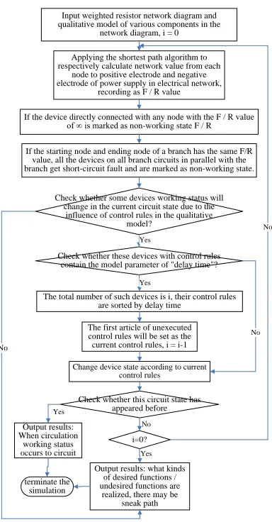
of various constituent devices, and the system working state can be obtained through qualitative emulator simulating the system operation. Qualitative simulation-based SCA analysis is to report the state combination of undesired functions by applying similar behavior principles on the basis of qualitative simulation so as to help and identify sneak circuit. Qualitative simulation process is shown in Figure 6:
Input weighted resistor network diagram and qualitative model of various components in the
network diagram, i = 0 Applying the shortest path algorithm to respectively calculate network value from each
node to positive electrode and negative electrode of power supply in electrical network,
recording as F / R value
If the device directly connected with any node with the F / R value of ∞ is marked as non-working state F / R
If the starting node and ending node of a branch has the same F/R value, all the devices on all branch circuits in parallel with the branch get short-circuit fault and are marked as non-working state.
Check whether some devices working status will change in the current circuit state due to the
influence of control rules in the qualitative model?
Change device state according to current control rules
Yes
Check whether this circuit state has appeared before
No
terminate the simulation
Yes
No
Check whether these devices with control rules contain the model parameter of "delay time"?
The total number of such devices is i, their control rules are sorted by delay time
Yes
No
The first article of unexecuted control rules will be set as the current control rules, i = i-1
Output results: When circulation
working status occurs to circuit
Output results: what kinds of desired functions / undesired functions are
realized, there may be sneak path
No
i=0?
Yes
Fig. 6 Qualitative Simulation Flowchart
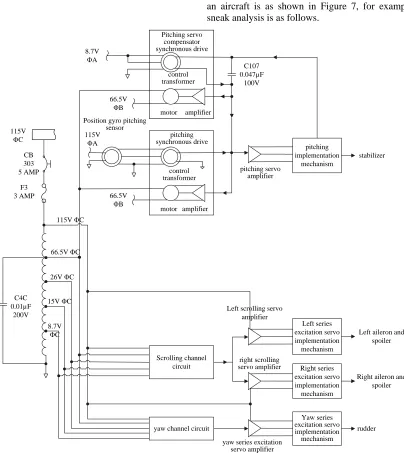
[image:4.612.330.522.198.566.2]4. CASE APPLICATION Part of the circuit in automatic control system of an aircraft is as shown in Figure 7, for example, sneak analysis is as follows.
yaw channel circuit 115V
ΦC
CB 303 5 AMP
F3 3 AMP
Scrolling channel circuit motor amplifier
control transformer
pitching synchronous drive
66.5V ΦB
motor amplifier
control transformer Pitching servo
compensator synchronous drive
66.5V ΦB
Yaw series excitation servo implementation mechanism Right series excitation servo implementation mechanism
Left series excitation servo implementation mechanism
pitching implementation
mechanism
C4C 0.01µF
200V
115V ΦC
66.5V ΦC
26V ΦC
15V ΦC
8.7V ΦC
stabilizer
Left aileron and spoiler
Right aileron and spoiler
rudder
yaw series excitation servo amplifier
right scrolling servo amplifier Left scrolling servo
amplifier C107 0.047µF
100V
115V ΦA
Position gyro pitching sensor 8.7V
ΦA
[image:5.612.110.514.105.558.2]pitching servo amplifier
Figure 7 Part of the Circuit in Automatic Control System of an Aircraft
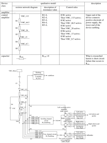
For the specific situation of various components, qualitative modeling for the above cases by applying the method described herein, qualitative modeling of some devices is as shown in Table 3, and the entire circuit is established with a weighted resistor network diagram after abstract and simplification, which is as shown in Figure 8.
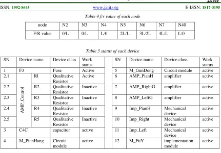
Qualitative simulation shall first calculate f / r values of each node, shown in Table 4, marking status of each device shown in Table 5, and then change qualitative resistance of F3 to ∞ according
to control law, some port value also changed according to “control law”, thereby it is required to recalculate f/r value of each node and determine the working condition of the device until the work status does not change.
Table 3 qualitative modeling of control amplifier and capacitor
Device class
qualitative model description
resistor network diagram description of resistance value
Control rules
amplifier … control
amplifier VΦC_115
VΦC_66.5
VΦC_26
VΦC_15
VΦC_8.7 R1
R2
R3
R4
R5
R1=L R2=L R3=L R4=L R5=L
If R1 active
Then VΦC_115 active;
If R2 active
Then VΦC_66.5 active;
If R3 active
Then VΦC_26 active;
If R4 active
Then VΦC_15 active;
If R5 active
Then VΦC_8.7 active;
Upper end of the device connects positive electrode of power supply, the lower end of the device earthing.
capacitor RC4C RC4C=0 What is researched
herein is short circuit failure that occurs to Rc4c
Yaw channel circuit
M_PianHang VΦC_More
N2
F3
N3
Scrolling channel circuit M_GunDong
Yaw series excitation servo implementation mechanism Imp_PianH Right series excitation servo implementation mechanism Imp_Right Left series excitation servo implementation mechanism
Imp_Left C4C
VΦC_115
VΦC_66.5
VΦC_26
VΦC_15
VΦC_8.7
N8 N18
N10 N11
N9 N13 N12 N14 N16 N15
N17 Left aileron and spoiler
Right aileron and spoiler
Rudder
Yaw series excitation servo amplifier
AMP_PianH Right scrolling servo
amplifier AMP_RightG
Left scrolling servo amplifier
AMP_LeftG N4
N5
N6
N7
N3
N3
N3 N3
N7 N4
N40
VΦC_115 VΦC_66.5 VΦC_26 VΦC_15 VΦC_8.7 VΦC_115 VΦC_66.5 VΦC_26 VΦC_15 VΦC_8.7
Pitching implementatio
n module
M_FuY
stabilizer
Table 4 f/r value of each node
node N2 N3 N4 N5 N6 N7 N40
F/R value 0/L 0/L L/0 2L/L 3L/2L 4L/L L/0
Table 5 status of each device
SN Device name Device class Work status
SN Device name Device class Work
status
1 F3 Fuse Active 5 M_GunDong Circuit module active
2.1
A
M
P
_Cont
rol
Rl Qualitative Resistor
Active 6 AMP_PianH amplifier active
2.2 R2 Qualitative
Resistor
Inactive 7 AMP_RightG amplifier active
2.3 R3 Qualitative
Resistor
Inactive 8 AMP_LeftG amplifier active
2.4 R4 Qualitative
Resistor
Inactive 9 Imp_PianH Mechanical
device
active
2.5 R5 Qualitative
Resistor
Inactive 10 Imp_Right Mechanical
device
active
3 C4C capacitor active 11 Imp_Left Mechanical
device
active
4 M_PianHang Circuit
module
active 12 M_FuY implementation
module
active
5. CONCLUSION
Based on qualitative simulation, this paper establishes SCA analysis techniques method which can easily conduct SCA analysis in functional level of the system and thus has its unique advantages in the early design stage lack of detailed information. The method can not only save a lot of business costs of SCA analysis, but also solve circuit analysis problems encountered in simulation overflow of quantitative digital simulation. Meanwhile, qualitative modeling technique in the method can easily extend to qualitative automated FMEA (Failure Modes and Effects Analysis) in the field, which has a great application prospect.
REFRENCES:
[1] Boeing Company, “The handbook of sneak circuit analysis”, 1991, pp. 52-94.
[2] Boeing Company, “Program requirements of automatic sneak circuit analysis”, 1991, pp. 95-144.
[3] G.H. Li, C.H. Hu, X.M. Ye, W. Zhang and T. Liu, “A retrospective and prospective review on sneak circuit analysis technology”, Journal of Safety and Environment, Vol. 4, No.1, 2004, pp. 84-88.
[4] B.J. Liu, C.H. Hu, “Sneak circuit analysis based on neural network”, Journal of Astronautics, Vol. 27, No. 3, 2006, pp. 474-477.
[5] H. Xu and L. Zhang, “Standard sneak circuit analysis and its application in China space reliability engineering”, Proceedings of 2009 8th international conference on reliability, maintainability and safety (ICRMS), Chinese Society of Aeronautics and Astronautics (China), July 20-24, 2009, pp. 91-94.
[6] Y. Mei, D.Y. Qiu, and B. Zhang, “Sneak circuit automatic identification method for power electronic converters”, Zhongguo Dianji Gongcheng Xuebao, Vol. 29, No. 3, 2009, pp. 23-28.
[7] Y. Hashiura, T. Fujimoto and T. Matsuo, “Qualitative simulation models for non-autonomous systems”, Proceedings of 21th international conference on systems engineering, University of Nevada Las Vegas, August 16-18, 2011, pp. 392-397.
[8] B.J. Liu, Y.Z. Liu and C.J. Wang, “Sneak path analysis of warship pipeline systems based on fuzzy qualitative simulation”, Journal of Nanjing University of Science and Technology, Vol. 35, No. suppl 2, 2011, pp. 77-81.
[image:7.612.95.526.67.367.2]complex system”, Information and Control, Vol. 30, No. 3, 2001, pp. 235-239.
[10]S. Yan, “Digital electronic technology”, Beijing: Higher Education Press, 1998.