LOAD BALANCING TECHNIQUE TO IMPROVE QoS FOR
LIGHTPATH ESTABLISHMENT IN OPTICAL WDM
NETWORKS
1M.R.SENKUMAR, 2Dr.K.CHITRA
1
Assistant Professor, Faculty of Electronics and Communication Engineering Jayasuriya Engineering College, Redhills Chennai
2
Professor, School of Electronics and Communication Engineering VIT University, VIT Chennai Campus, Chennai
E-mail: [email protected]
ABSTRACT
This paper discusses the issue of providing basic QoS in optical burst-switched WDM networks. As in WDM networks, end-to-end connection demands are dynamic routes, it changes the state according to the current network traffic status. In order to improve the basic QoS, load balancing technique for lightpath establishment in Optical WDM Networks has been proposed. This approach contains three phases; initially the network’s traffic is predicted with Hidden Markov Model (HMM). In the second phase wavelength ordering technique is implemented where the crosstalk in the network is reduced. In the final phase an objective function based on GRASP is considered for the predicted traffic load from phase-1. Through this approach, it is shown in this paper that the Qulaity of service (QoS) in the optical WDM network can be improved in terms of delay, throughput and blocking probability.
Keywords:QoS, Optical WDM, Hidden Markov Model, Wavelength Ordering Technique
1. INTRODUCTION
1.1. Optical Wavelength Division Multiplexing (WDM)
WDM is the multiplexing technique that exploits the huge bandwidth capacity of the fibre by immediate transmission of packets of data over multiple wavelength channels.
Nowadays, WDM is widely used for expanding capacity in optical networks. In a WDM network, each fibre link can carry high-rate traffic at many different wavelengths and hence multiple channels can be created within a single fibre. In addition to huge amount of bandwidth, all-optical WDM networks allow high-speed data transmission without electronic converters at intermediate node and transparency with respect to data format to be achieved.
The recent advances in networking, particularly in high-capacity optical networking that employs WDM have made bandwidth-intensive multicast applications such as high-definition television, video conferencing, interactive distance learning, live auctions, distributed games and movie broadcasts widely popular.
As demand increases for more robust communication in order to support our growing dependence on rapid access to information, the need for efficient and reliable networks becomes critical. The use of WDM technology has enabled us to meet these demands by taking advantage of the huge capacity of optical fibres.
There are mainly two basic architectures used in WDM networks: ring and mesh. But the majority of optical networks in operations have been built based on the ring architecture. Still carriers have considered more the mesh architecture as an alternative for building their next generation networks.
A WDM network usually consists of routers that are connected by a set of wavelength cross connects (WXC) for switching traffic across lightpaths and an optical add drop multiplexer (OADM) for adding or dropping traffic to/from several wavelengths. [1][2][3][4][5][6].
1.2. QoS in Lightpath Establishment in Optical WDM Networks
A lightpath that originates and terminates at IP routers is subjected to wavelength constraint, whereby it must use the same wavelength on all links along the chosen physical path. If a sequence of more than one lightpath is required to transfer a message from an ingress router to egress router, optical switching occurs within a lightpath and opto-electronic-opto (o-e-o) switching takes place between two consecutive lightpaths.
The classical techniques for QoS provisioning in IP networks are difficult to apply in all optical networks as there is no optical counterpart to store and forward model that command the use of buffers for queuing packets during contention for bandwidth in electronic packet switches. Hence, WDM network with QoS assurance is a promising technique for the next generation optical communication system. QoS provisioning of light paths in WDM network describes the routing models that facilitate the signal quality guaranteed transmission over the optical fibre for long distance network.
The current IP provides only best effort service, but the mission-critical and real time application require a high QoS (e.g., low delay, jitter and loss probability) supporting the basic QoS at the WDM layer to facilitate as well as complement a QoS enhanced version of IP (such as Ipv6). Moreover, it is necessary not only for carrying some WDM layer traffic such as those for signalling and protection/restoration purposes that require higher priority than other ordinary traffic, but also for supporting certain applications directly (bypassing IP) or indirectly.
Even though QoS is not directly responsible for ensuring that the network is up and running all the time, still it has a direct impact on the survivability of the network. Generally QoS requirements extend network resource utilization that is assured through bandwidth trading. [1][3][7][8].
1.3. Issues of QoS in Lightpath Establishment in Optical WDM Networks
Some of the major issues that need to be considered in order to provide QoS lightpath establishment in optical WDM networks
• In a wavelength-routed optical network, the failure of a network element (for e.g. fibres in a duct and cross connects) can cause the failure of several lightpaths and hence leading to large data and revenue loss.
• In case of non-ideal fibre, lightpath provisioning without considering the physical
layer impairment doesn’t satisfy the signal quality guaranteed transmission.
• WDM layer traffic must support certain applications through other legacy or new protocols incapable of QoS support.
• At the WDM layer huge traffic need to be maintained, since it contains all optical fibres which may result in huge bit error rate and also increased blocking probability rate [2][9][10] [11].
Puype, Bart, et al [14] have proposed an algorithm for the proactive Virtual Topology Reconfiguration by considering QoS parameters for Multihop IP-over WDM optical networks with Gaussian traffic model. The new traffic model uses wavelet neural network based traffic prediction. But load balancing and wavelength blocking in the network are not considered.
Jun He et al [12] have proposed QoS aware wavelength assignment algorithms that consider both bit-error rate (BER) and latency constraints. A novel wavelength assignment technique called wavelength ordering is shown via simulation to reduce the call blocking probability resulting from both physical impairments and excessive processing delay caused by channel BER estimation.
Francesco Palmieri et al [13] have proposed an efficient re-optimization technique based on a GRASP meta-heuristic. Connections are ordinarily routed dynamically using one of the available algorithms for online routing, but occasionally, when reorganization of the current virtual topology is desirable, existing paths are re-routed in order to improve load balancing and hence the ability to efficiently accept further connections. The simulation results demonstrate that several network performance metrics – including connection blocking ratios and bandwidth gains – are significantly improved. The drawback of the proposed method is that they are not energy efficient.
2. PROPOSED SOLUTION 2.1. Overview
In this paper, we propose a load balancing technique to improve the QoS for light path establishment in WDM networks. This technique uses a Hidden Markov Model (HMM) based traffic prediction along with QoS aware wavelength assignment and proactive Virtual Topology Reconfiguration.
Here, we enhance the traffic prediction model of [14] using HMM and the GRASP based meta heuristic model [13] in order to minimize the lightpath rejection or delayed creation and to balance the load on the optical links that ultimately maximize the network resource utilization. Then the wavelength ordering method is implemented [12] in which wavelength order is determined to minimize the average crosstalk in the network for a given traffic and hence it provides better solution to overcome wavelength blocking.
The different phases of our proposed solution can be briefly explained as follows:
• Phase 1: In this phase, traffic prediction model is constructed based on HMM
• Phase 2: In this phase wavelength ordering [12] is implemented in order to determine the wavelength order and hence it helps to avoid the average crosstalk in the network.
• Phase 3: In this phase, an objective function based on GRASP [13] is formulated based on the predicted traffic load from phase-1. The chosen objective function value clearly determines how the virtual topology is best suited for the given traffic demand. When the traffic pattern changes, the virtual topology needs to be changed to reflect the objective function goals. Hence it provides a useful strategy to improve QoS level defined by desired maximum utilization rate.
Advantages
• The proposed method provides best solution for load balancing and also minimizes the lightpath rejection in the network.
• It provides method to minimize the crosstalk that increases the blocking probability in the network.
• It also proposes efficient utilization of resources available in the network.
2.2. Computation of Load
Consider the network topology as a graph G = (N, L, W, F), where N and L represents node and link respectively. Each link is made up of collection of fibers and W in the graph representation symbolizes wavelengths [20].
Total load on a link L can be represented as,
Load
L
(s,d) =∑
∈R d s r
Wi Li d s r
N
) , (
), ,
( (1)
Where, r(s,d) is the route from the source to the destination. R is the set of all routes for every source and destination. Wi denotes available wavelength on that link. Generally, the variable
Wi Li d s r
N
), , (
that gives the value of link load takes value either 0 or 1. (i.e)
Wi Li d s r N
), , ( =
0 1
if the route used the wavelength Wi on the link Li.
2.3. Hidden Markov Model (HMM)
HMM is a stochastic signal model that offers theoretical description of a signal processing system. An HMM encompass of recurrent finite-state Markov Chain, output symbols and a distribution over that alphabet for each transition in the Markov Chain. In HMM, the states and transitions are hidden and output can only be seen through symbols. The set L = (L1, L2, • • •, LN−1, LN) are hidden layers, they are not visible but arbitrarily generates the mixture of observations. The probability of the succeeding state depends on the previous state [15][16].
HMM includes the set of hidden layers L and set of observation states O. The basic representation of HMM is shown below in fig.1. The set of hidden layers and observation states are represented below respectively,
) ,..., , ,
(l1l2 l3 ln L=
(
o o o om)
O= 1, 2, 3,...,
Let Q be the state sequence of fixed distance D, to corresponding remarks R,
D
q q q q
Q= 1, 2, 3,...,
D
r r r r
R= 1, 2,3,...,
HMM is generally formulated as [17]
(
ABπ)
λ= , , (2)
(
o l o l)
P A i t j t ij ija
a
= = = = −1 |
, (3)
where as array of observation is represented by B and is independent of time t. It stores the probability of observation, which is produced from the state. The observation array B is detailed in equation (4)
( )
[
b k]
b( )
k P(
x o q l)
B= i , i = t = k| t = i (4) It signifies the initial state probability as shown below,[ ]
i i =P(
n =Ii)
= π ,π 1
π (5)
Fig.1. Hidden Markov Model
2.3.1. Prediction of Traffic
In this approach in order to achieve the QoS, the traffic condition of the network should be predicted. This HMM prediction model takes traffic load of future traffic of flows as hidden states and link loads on current traffic as observing states (O).
Let L be the set of hidden layers as, l l l L n ,..., ,2 1
= (6)
Let O be the set of observation states as shown below,
o o o
O= 1, 2,..., n (7)
Let S be the state sequence of length L to corresponding observation O as,
s s s S L ,..., , 2 1
= (8) During the prediction interval time Tp, each intermediate nodes along the path of given source and destination pair estimates the link holding time (H) and pass that value to the HMM prediction model as observation state. HMM predicts H of the flows for the future interval with the observation sequence S. Finally, from the destination, the
connection holding time of the entire path is forwarded to the source node.
The probability of the observation (O) in a given sequence S is, [19]
(O S λ) (ol sl λ) bs o bs o bsL oL L l ) ( )... ( ) ( , | Pr , |
Pr 1 1 2 2
1 × = =
Π
= (9)State sequence probability is as follows,
(
S
|
)
s1a
s1s2a
s2s3...
a
sL 1sLPr
λ
=
π
− (10)Network can easily estimate the probability of observations using equation (13), (14) as below,
(
) (
)
o b a o b a o b π λ S λ S O λ O L sL sL sL s s s s sL s s N ) ( )... ( ) ( | Pr , | Pr ) | Pr( 1 2 2 2 1 1 1 ... 1 1 −∑
∑
= = (11)using Viterbi algorithm to find the solitary state sequence for an observation sequence s1. To discover highly likelihood state, the network first outline the probability of the most possible path as, [19]
(
s s s O o o o λ)
O i
ς L i l
nL s s s | ... , , ... , )
( 1 2 1 2
1 ,... 3 , 2 , 1
max
= = − (12)By using the above mentioned probability function, network can decide the highly likelihood state as shown below,
arg *
= L
n
[
L( )
i]
L i
ς
max
1≤≤
(13)
At each step, the sequence of states can be backtracked as the pointer. The back tracking process of state sequence is given below, [19]
L L l n
n l l
L . 1 ,..., 2 , 1 , * 1 1 * − − = Ψ = +
+ (14)
Where ψ is an additional matrix of S*L, this matrix should be added in Viterbi algorithm to the optimal state. L denotes the state sequence length time. This backtracking provides the required set of states.
2.4. Wavelength Assignment
In this section a wavelength ordering algorithm is explained. By this wavelength ordering algorithm it is possible to reduce the crosstalk in the network. Since the adjacent channel interference can be the reason for the limiting degradation in WDM networks.
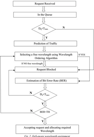
required wavelength. These received requests will be queued and the centralized controller takes the first call from the queue, assigns it a wavelength and then starts an iterative process to select a wavelength. Then the queuing delay is estimated. If this queuing delay is greater than a threshold value, the received request will be blocked otherwise the traffic will be predicted (from sec 2.3). Based on
[image:5.595.144.451.216.661.2]the predicted traffic in the network, the wavelength is allocated using wavelength ordering algorithm. If no free wavelength is found, the request will be rejected. Otherwise after estimating the delay (Da(k)) which incurred during the connection admission control (CAC) procedure and BER (bit error rate),. the requested wavelength is allocated.
Fig .2. QoS-aware wavelength assignment
The total call admission time for call request can be written as the sum of two delays: queuing delay and a processing delay,
(k) D (k) D (k)
Da = q + p (15)
Where,
Da(k) is the delay incurred during CAC procedure.
Dq(k) is the queuing delay which is the time request must wait in the queue and it depends on the sum of the Processing delay of previous requests in the queue.
Yi a
(k) D
m
i TH LP
p
∑
= + =
1
τ (16)
Where,
m denotes the number of trials before the processor finds a viable (BER less than threshold TH) lightpath.
τLP is the time required for calculating the set of free wavelengths.
TH is the threshold value, the time needed for checking if the BER of a candidate or interacting lightpath is higher than the BER threshold.
Yi is the number of interacting lightpaths tested before the failure occurs.
2.4.1. Wavelength Ordering Algorithm
The wavelength ordering algorithm used in this approach is based on a new heuristic offline wavelength ordering technique. Heuristic offline wavelength ordering technique allocates the wavelength to the received request which results in reducing the crosstalk.
Step 1: W0 and Ws be the two wavelength arrays, corresponding to successive wavelength sequences, the successive wavelengths are {λ1, λ2,…, λj,….
W}. initially set W0 to λ1 and Ws contains other wavelengths.
Step 2: Estimate the crosstalk power level PC(j,l)
for wavelength λj in Ws to every λl in W0 by PC(j,l)
= exp (-α|l-j|) for some constant α >0.
Step 3: Generate a set Wk consisting of all member wavelengths with the same minimum worst-case crosstalk level minλjϵWs minλlϵW0 PC (j,l).
Step 4: Recognise the next wavelength to be added to the ordered list, λj= arg minλkϵWk ΣλlϵW0 PC(k,l).
Append λj to W0and remove it from Ws.
Step 5: Repeat from step 2 until Ws is empty.
Step 6: return ordered wavelength sequence W0 ϵ W.
The main aim of this algorithm is that at any point the next wavelength to be utilized should be as far as possible spectrally separated from any previously assigned wavelengths, since the corresponding crosstalk is shown as exponentially reducing with spectral separation. The first two wavelengths on the ordered list are the extreme points, i.e, wavelength slots labelled 1 and W. Once ordered, these are removed from the unordered wavelength list. The wavelength ordering algorithm
creates the ordered list by successively engaging a wavelength from the remaining unordered wavelength set that has the largest separation from all the wavelengths in the ordered list. If there are few wavelengths with the same crosstalk influence, the wavelength whose sum of crosstalk contributions to all already-sorted wavelengths is minimum is chosen, as stated on line 4 in Algorithm 1. For example, if there are 8 wavelengths then the resulting ordering is (1, 8, 4, 6, 2, 7, 3, and 5). Again the term channel is used here to refer to the place in the ordered list, and is not the same as the wavelength number; in our example channel 2 represents wavelength 8.
2.5. The Objective Function
The ultimate objective of the offline re-optimization problem is to minimize the lightpath rejection or delayed creation (due to the duration of the re-optimization process) while balancing the load on the optical links (and hence maximizing network resources utilization).
Objective Function Algorithm
Step1:Input construction phase Xp and
neighbourhood function N
Step 2: New network condition Xp*
Step 3: Assign Xp* to NULL (Xp* Ф)
Step 4: for i=1 to |X| do
Step 5: X` X\{coni}
Step 6: X` X ∪{coni} Step 7: If f(X`)<=f(X*) then
Step 8: X*X`
Step 9: If local search type=”depthsearch” then
Step 10: XX`
Step 11: end
Step 12: end
Step 13: end
Step 14: return X*
Step 15: end
Every connection request coni in the network is
obtained one at a time during the prediction of network’s traffic phase (sec 2.3) and ultimately re-routed in the network. Then, the objective function is evaluated on the new network X` and the best network solution X* is eventually updated with the new value. If the depth local search is chosen, the next iteration will start its local search from the new network solution X`; else, a breadth local search will be executed, starting from X i.e. initial network condition.
W W (X)
f res
) 1
var(
max
−
= (17)
f() is the objective function where variance of the load compares with capacity ratios for each link. Wres is the residual wavelength.
Wmax is the maximum wavelength.
The selected objective function value evidently determines how the virtual network topology is best suited for the given network’s traffic demand. The minus sign accounting for the fact that network is demanding to balance the load as evenly as possible. Since the traffic pattern changes the network condition and may not remain optimal, the virtual network topology needs to be changed to replicate the objective function goals.
3. SIMULATION RESULTS
3.1.Simulation Model and Parameters
The Network Simulator (NS-2) [18], is used to simulate the proposed architecture. In the simulation, 14 nodes are connected together by WDM network. The simulated traffic is Constant Bit Rate (CBR) and Exponential. In this simulation, 10 source nodes send their sensor data through the link.
The simulation settings and parameters are summarized in table-1.
Table.1. Simulation Settings No. of Nodes 14
Network WDM
No. of Wavelength 4,6,8,10 and 12 No. of Traffic Connections 4,6,8 and 10
Simulation Time 25 sec Traffic Source CBR and Exponential
Packet Size 512
Sources 10
Rate 10,20,30,40 and 50Mb
3.2.Performance Metrics
The proposed Load Balancing Technique to improve QoS for Lightpath Establishment (LBIQLE) is compared with the GRASP technique [13]. The performance is evaluated mainly, according to the following metrics.
Bandwidth Utilization: It refers to the fraction of bandwidth utilized by the receiver from the total available bandwidth
Blocking Probability: It is the probability with which the number of packets rejected during the transmission.
Delay: It is the amount of time taken by the nodes to transmit the data packets.
3.3. Results
Case-1 (CBR Scenario)
In case-1, CBR traffic flows are transmitted from different source to destinations. For this scenario, the traffic rate, wavelength and number of connections are varied.
1) Based on Rate
Here the number of CBR traffic connections is fixed as six and the traffic rate is varied from 10 to 50Mb.
Rate Vs Bandwidth Utilization (CBR)
0 0.5 1 1.5
10 20 30 40 50
Rate(Mb)
U
t
il
iz
a
t
io
n
GRASP LBIQLE
Fig.3. Rate Vs Utilization
Rate Vs Blocking Probability (CBR)
0 0.2 0.4 0.6 0.8 1
10 20 30 40 50
Rate(M b)
B
lo
c
k
in
g
P
ro
b
a
b
il
it
y
GRASP
LBIQLE
Fig.4. Rate Vs Blocking Probability
Rate Vs Delay (CBR)
0 0.1 0.2 0.3 0.4 0.5
10 20 30 40 50
Rate(Mb)
D
e
lay
(S
e
c)
GRASP
LBIQLE
Fig.5. Rate Vs Delay
Fig.3 to 5 show the bandwidth utilization, blocking probability and delay, respectively, for both the schemes when the rate is increased. From the figures, we can see that LBIQLE has 57% more utilization, 33% lesser blocking probability and 30% lesser delay than GRASP.
Here the number of CBR traffic connections and the traffic rate is fixed as six and 10Mb. The wavelength number is varied from 4 to 12.
Wavelength Vs Bandwidth Utilization (CBR)
0 0.5 1 1.5
4 6 8 10 12
Wavelength
U
t
il
iz
a
t
io
n
GRASP
LBIQLE
Fig.6. Wavelength Vs Utilization
Wavelength Vs Blocking Probability (CBR)
0 0.5 1
4 6 8 10 12
Wavelength
Bl
o
c
k
in
g
P
ro
b
a
b
li
ty
GRASP LBIQLE
Fig.7. Wavelength Vs Blocking Probability
Wavelength Vs Delay (CBR)
0.15 0.16 0.17 0.18 0.19 0.2
4 6 8 10 12
Wavelength
D
e
la
y
(S
e
c
)
GRASP LBIQLE
Fig.8. Wavelength Vs Delay
Fig.6 to 8 show the bandwidth utilization, blocking probability and delay, respectively, for both the schemes when the wavelength is increased. From the figures, we can see that LBIQLE has 38% more utilization, 28% lesser blocking probability and 11% lesser delay than GRASP.
3) Based on No. of Traffic Connections
Here the traffic rate is fixed as 10Mb and wavelength is fixed as 6. The number of CBR traffic connections is varied as 4,6,8 and 10.
No.of connections Vs Bandwidth Utilization(CBR)
0 0.5 1 1.5
4 6 8 10
Conne ctions
Ut
il
iz
a
ti
o
n
GRASP LBIQLE
Fig.9. No. of connections Vs Utilization
No.of connections Vs BlockingProbability(CBR)
0 0.5 1
4 6 8 10
Conne ctions
B
lo
c
k
in
g
P
ro
ba
b
il
it
y GRASP
LBIQLE
Fig.10. No. of connections Vs Blocking Probability
No.of connections Vs Delay(CBR)
0 0.1 0.2 0.3 0.4 0.5
4 6 8 10
Connections
D
e
la
y
(S
e
c
)
GRASP
LBIQLE
Fig.11. No. of connections Vs Delay
Fig.9 to 11 show the bandwidth utilization, blocking probability and delay, respectively, for both the schemes when the number of connections is increased. From the figures, we can see that LBIQLE has 50% more utilization, 28% lesser blocking probability and 54% lesser delay than GRASP.
Case-2 (Exponential Scenario)
Rate Vs Bandwidth Utilization(Expo)
0 0.005 0.01 0.015 0.02
10 20 30 40 50
Rate(Kb)
Ut
il
iz
a
ti
o
n
GRASP LBIQLE
Fig.12. Rate Vs Utilization
Rate Vs BlockingProbability(Expo)
0 0.2 0.4 0.6
10 20 30 40 50
Rate(Kb)
B
lo
c
k
in
g
P
ro
b
a
b
ilit
y
GRASP
LBIQLE
Fig.13. Rate Vs Blocking Probability
Rate Vs Delay(Expo)
0 1 2 3 4
10 20 30 40 50
Rate(Kb)
D
e
la
y
(S
e
c
)
GRASP
LBIQLE
Fig.14. Rate Vs Delay
Fig.12 to 14 show the bandwidth utilization, blocking probability and delay, respectively, for both the schemes when the rate is increased. From the figures, we can see that LBIQLE has 59% more utilization, 31% lesser blocking probability and 37% lesser delay than GRASP. When compared to CBR traffic, the percentage improvement in bandwidth utilization and delay is slightly better for LBIQLE for exponential traffic.
4. CONCLUSION
For every optical WDM networks the basic QoS has to be provided. To provide the basic QoS a load balancing technique is proposed to improve the Lightpath Establishment in Optical WDM Networks. This approach can be implemented in three phases; in the initial phase the traffic prediction is done based on HMM. Then in the second phase, a wavelength ordering technique is
implemented where the crosstalk in the network is reduced. During the wavelength ordering technique the queuing delay and delay incurred during CAC procedure are considered. In the final phase of the approach an objective function based on GRASP is designed considering the predicted traffic load from phase-1. The advantage of this approach is that the crosstalk in the network is reduced and also rejection of the lightpaths is reduced and even the network resources are allocated in an efficient manner. Simulation results show that the proposed techniques reduces the blocking probability and delay while increasing the bandwidth utilization for both CBR and Exponential type of traffic.
REFERENCES
[1] V V, Dhanya. Design of QoS aware light path provisioning mechanisms in WDM network. Diss. 2012.
[2] Idzikowski, Filip, Luca Chiaraviglio, and E. Bonetto. "EWA: An adaptive algorithm for energy saving in IP-over-WDM networks." Networks and Optical Communications (NOC), 2012 17th European Conference on. IEEE, 2012.
[3] Kavian, Yousef S., et al. "Network Topology Effect on QoS Delivering in Survivable DWDM Optical Networks." Journal of Telecommunications and Information Technology 1 (2009): 68-71.
[4] Jumpot Phuritatkul, “Quality Of Service Provisioning In WDM Optical Burst Switching Networks” The Graduate University for Advanced Studies (SOKENDAI), Ph.D. thesis, 2005.
[5] Kim, Sun-il, and Steven S. Lumetta. "Protection Based QoS in WDM Mesh Networks" UIUC Center for Reliable and High-Performance Computing Technical Report CRHC-06-01 (also UILU-ENG-06-2204), 2006.
[6] Kiran, G. Raghu, and C. Siva Ram Murthy. "QoS based survivable logical topology design in WDM optical networks." Photonic Network Communications 7.2 (2004): 193-206.
[7] Mohan, Gurusamy, and E. Cheng Tien. "QoS routing in GMPLS-capable integrated IP/WDM networks with router cost constraints." Computer communications 31.1 (2008): 19-34.
Communications Magazine, IEEE 40.12 (2002): 38-43.
[9] Ou, Canhui, et al. "Subpath protection for scalability and fast recovery in optical WDM mesh networks." Selected Areas in Communications, IEEE Journal on 22.9 (2004): 1859-1875.
[10]Yoo, Myungsik, Chunming Qiao, and Sudhir Dixit. "QoS performance of optical burst switching in IP-over-WDM networks." Selected Areas in Communications, IEEE Journal on 18.10 (2000): 2062-2071.
[11]Yoo, Myungsik, Chunming Qiao, and Sudhir Dixit. "QoS performance of optical burst switching in IP-over-WDM networks." Selected Areas in Communications, IEEE Journal on 18.10 (2000): 2062-2071.
[12]He, Jun, Maïté Brandt-Pearce, and Suresh Subramaniam. "QoS-aware wavelength assignment with BER and latency constraints for all-optical networks." Journal of lightwave technology 27.5 (2009): 462-474.
[13]Palmieri, Francesco, Ugo Fiore, and Sergio Ricciardi. "A GRASP-based network re-optimization strategy for improving RWA in multi-constrained optical transport infrastructures." Computer Communications 33.15 (2010): 1809-1822.
[14]Puype, Bart, et al. "Multilayer traffic engineering for multiservice environments." Photonic Network Communications 18.2 (2009): 150-159.
[15]Rahul Khanna and Huaping Liu, “System Approach to Intrusion Detection Using Hidden Markov Model”, Proceedings of the international conference on Wireless communications and mobile computing, (IWCMC '06), 2006
[16]“Hidden Markov Models” Phil Blunsom [email protected] August 19, 2004
[17]Phil Blunsom, “Hidden Markov Models” The University of Melbourne, Department of computer science, digital.cs.usu.edu, 2004.
[18]Network Simulator: