A TECHNIQUE FOR ICI CANCELLATION USING
BAYESIAN PROBABILITY AND PARALLEL
CANCELLATION (BPICI)
1K. CHINNUSAMY, 2 K. DURAISWAMY
1
Professor Department of ECE
Vivekanandha College of Engineering for Women 2Dean Department of Computer Science and Engineering
K.S.R College of Technology E-mail: [email protected]
ABSTRACT
In past decade, the detection and mitigation of Intercarrier interference (ICI) in MIMO-OFDM system has been studied by various researchers due to the presence of frequency offset. Literature presents several works for ICI cancellation as like, iterative receivers, parallel cancellation (PIC) and so on. Among various techniques, researchers have put much concentration on PIC detectors which is a non-linear Multi-User Detection technique wherein the transmitted signal of each user is detected in parallel over a number of iterations. In this paper, Bayesian Probability based Intercarrier Interference Cancellation techniqueis proposed. The technique employs Bayesian probability computation process and parallel cancellation.The transmitted signals are received by the receiver section which consists oftwo cancellation stages. In the first stage, hard decision based decoding is carried out for spatial dimensions and in the second, Bayesian probability is employed after parallel interference cancellation.For the evaluation purpose, BER curves are plotted. Various curves are obtained by varying the fading channel, number of user signals and number of antennas Comparative analysis is also made by comparing to other techniques such as PIC and MVDR. From the results, we can see that our proposed technique has achieved better performance by having lower BER.
Keywords: Multiple- Input Multiple-Output (MIMO), Orthogonal Frequency Division Multiplexing
(OFDM), Intercarrier Interference, PIC, Bayesian Probability, BER
1. INTRODUCTION
Over the time, the forms of communication have changed like anything through the fast development of technology. The message is in the form of data transmitted over a channel in data communication. Throughout the past two decades, the fast development of digital integrated circuit technologies had directed to ever more cultured signal processing systems [8][9]. A general digital communication system consists of three basic elements: a transmitter, a communication channel and a receiver [10]. Both the transmitter and the receiver could either be fixed or mobile, and they are detached by the channel. The channel can be wire line or wireless [11]. A communication system is defined by three parameters: bandwidth efficient, power efficient, or cost efficient. There is a high priority on bandwidth efficiency in most of the systems [12].The increasing developments of telecommunication raise the need for efficient
usage of spectral resources, so the multiplexing techniques in particular the multi-carrier modulation are widely used to optimize these resources [7]. To transfer a digital bit message stream (lower frequency) over a channel, digital communication systems use modulation for avoiding attenuation. Several modulation methods are used in communication systems. OFDM (Orthogonal Frequency Division Modulation) is a frequency-division multiplexing (FDM) scheme used as a digital multi-carrier modulation method to attain high data rates and permits digital data to be efficiently and consistently transmitted over a radio channel, even in multipath environments [15]. OFDM is spectrally efficient and equalization is very simple compared to Single-Carrier systems [14] and has been implemented in several wireless standards.
to achieve significant goals of good coverage in a non-line-of-sight (LOS) environment, reliable transmission, high peak data rates and high spectrum efficiency. Multiple antennas at the transmitter and receiver offer assortment in a declining environment and this significantly increase the system capacity [15, 16]. At the receiver, multiple antennas are used to discrete spatial multiplexing streams. OFDM is selected over a single-carrier solution due to lower complexity of equalizers for high delay spread channels or high data rates [17]. In OFDM, the computationally-efficient
Fast Fourier Transform (FFT) is used to transmit data in parallel over a large number of orthogonal subcarriers.In MIMO-OFDM systems, at the receiver side multi-stream detection is required to cancel out interference effects.The basic principle behind IC (Interference Cancellers) detectors is to estimate the interference signals and then remove all or part of the multiple access interference (MAI) seen by the user of interest before demodulating the user's signal. PIC (Parallel Interference Canceller) is one of the nonlinear MUD (Multi User Detectors) employed in vast areas. It possesses several desirable properties, such as the potential for near optimum performance, very low computational complexity and low decision latency. Parallel interference cancellation technique is more practical with its low computational complexity.
BPICI (Bayesian Probability based Intercarrier Interference Cancellation) techniqueis proposed in this paper. The technique employs Bayesian probability computation process and parallel cancellation.The transmitted signals propagate through the channel and are received by the receiver section. In the receiver, hard decision decoding on spatial dimension is carried out and subsequently, parallel cancelation is carried out. It is improved by the use of Bayesian probability. Contributions of the proposed technique:
• The paper discusses MIMO-OFDM system using Bayesian Probability based Intercarrier Interference Cancellation technique.
• Both the Rayleigh and Rician fading channels are considered independently.
• BER curves are plot for the evaluation purpose. Various curves are obtained by varying the fading channel, number of user signals and number of antennas.
• BER curves are drawn for proposed BPICI, PIC and MVDR.
The rest of this paper is organized as follows. Section 2 gives a brief description of the related works and in section 3, the proposed BPICI technique is described in a detailed manner. The results and discussions are presented in section 4, and section 5 gives conclusion.
2. RELATED WORKS
There has been several works in the literature related to PIC in MIMO- OFDM systems and in this section we confer the some of those works. Chao-Wang Huang et al. [1] designed a message passing MIMO data detector/ decoder with progressive parallel inter-carrier interference canceller (PPIC) which was based on factor graph for OFDM-based wireless communication systems. By exchanging messages both in space domain and frequency domain, the proposed algorithm was able to suppress inter-antenna interferences and cancel inter-carrier interferences iteratively and progressively. They obtained good results. Pankaj Kumar Sharma et al., [2] have discussed a partial transmit sequence (PTS) scheme to reduce the peak to average power ratio (PAPR) in multiple input multiple output orthogonal frequency division multiplexing (MIMO-OFDM) systems. In their method, the conjugate symbols on two antennas had the same property with orthogonal space time block coded (STBC). Their method is based on selecting part of the OFDM signal from all possible signals to make better tradeoff between PAPR reduction and computational complexity. The experimental results have shown the efficiency of their method when compared to the conventional PTS schemes in terms of PAPR reduction and bit error rate (BER).
for practical scenarios in which a part of subcarriers were assigned to a user. The enhanced WBP scheme was a widespread scheme of which narrow-band precoding and conventional WBP schemes were special modes.
Yechang Fang et al. [5] suggested a blind multiuser detection approach based on Fast ICA (fast fixed-point algorithm for independent component analysis) for a SDMA-aided (Spatial Division Multiple Access) MIMO OFDM system with additive white Gaussian noise (AWGN) for the target of better reliability. The proposed method offered better BER performance than usually-used spatial-multiplexing-based MIMO OFDM system. Simulation results established the better reliability of the proposed approach. Xu et al. [6] discussed an H-infinity estimator over time-invariant system models that modified the Krein space accordingly. In order to remove the large matrix inversion and multiplication required in each OFDM symbol from different transmit antennas, expectation maximization (EM) was established to minimize the high computational load. Joint estimation over multiple OFDM symbols were used to resist the high pilot overhead produced by the increasing number of transmits antennas. The performance of
the proposed estimator was improved via an angle-domain process.
3. PROPOSED BPICI CANCELLER
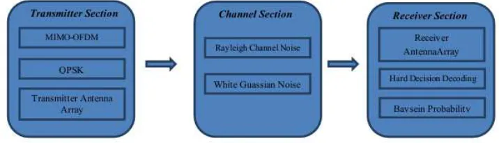
[image:3.612.128.486.429.532.2]In this paper, parallel interference canceller (PIC) is proposed for MIMO-OFDM based wireless communication systems using Bayesian probability computation process and parallel cancellation. MIMO (Multi-Input Multi-Output)systems are which has more than one input and more than one output. In Orthogonal Frequency Division Multiplexing (OFDM), digital data are encoded on multiple carrier frequencies. The signals are transmitted by the antenna array set which propagates through the channel and are received by the receiver antenna array after travelling through the channel. When the signal is propagated through the channel, channelnoise(Rayleigh channel noise) and the White Gaussian Noise (WGN) are added to the signals. In the receiver, hard decision decoding on spatial dimension is carried out and subsequently, Bayesian probability is employed to complete the proposed BPICI (Bayesian Probability based Intercarrier Interference Cancellation) technique. The block diagram of the proposed technique is given in figure 1.
Figure 1: Block Diagram Of The Proposed BPICI Technique
a) Transmitter Section
In the transmitter section, the input data is initially orthogonalfrequency division multiplexed which is then QPSK modulated. It is then taken inverse FFT and finally transmitted through the antenna arrays. Consider there are
N
signals in the user input serial signal data and let it be represented asG
which is defined by equation (1):) 1 ( )
, , ,
(g1 g2 gN T
G= K
The serial data is then split into parallel data streams or channels using orthogonal frequency division multiplexing. OFDM has the benefit that it has the ability to eliminate intersymbol interference
(ISI) and also achieves higher diversity gain and signal-to-noise ratio. The serial data (
G
) is converted intoK
number of parallel data streams. Let eachparallel data stream be represented as Gi(where0<i≤K) and G would contain defined i
number of data bits from the input stream
g
i(where
0
<
i
≤
N
), which means{gi}∈Gj. The operation can be mathematically noted as:) 2 ( )
, , ,
(G1G2 GK T
G= K
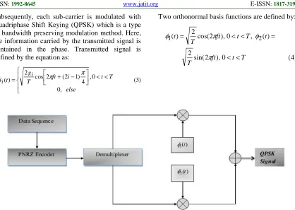
Subsequently, each sub-carrier is modulated with Quadriphase Shift Keying (QPSK) which is a type of bandwidth preserving modulation method. Here, the information carried by the transmitted signal is contained in the phase. Transmitted signal is defined by the equation as:
) 3 ( ,
0
0 , 4 ) 1 2 ( 2 cos 2 ) (
< <
− + =
else
T t i
ft T
g t S
i i
π π
Two orthonormal basis functions are defined by:
) 4 ( 0
), 2 sin( 2
) ( , 0 ), 2 cos( 2 )
( 2
1
T t ft T
t T t ft T
t
< <
= <
< =
π
φ π
[image:4.612.99.517.76.373.2]φ
Figure 2: Block Diagram Of QPSK Transmitter
QPSK transmitter block diagram is given in figure 2. Initially, incoming sequence is convertedinto polar form by Polar Non-Return to Zero (PNRZ) encoder. The resultant is split into waves consisting of odd and even numbered bits by the use of a demultiplexer. The waves are then multiplied with the respective orthonormal signal functions of
φ
1(t)andφ
2(t). The resultant waves obtained are then summed up to have the final QPSK modulated signal.Let the QPSK modulated signal be represented by Siwhere Siis the QPSK modulated signal
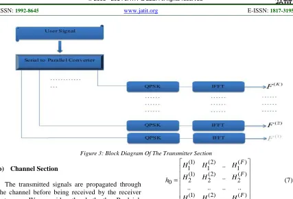
corresponding to inputGi. Subsequently, Inverse Fast Fourier Transform (IFFT) is applied on the
modulated signal to have
F
(i), where 0<i≤K .This signal
F
(i)is fed into the antenna Ani and istransmitted through the channelCh . The block
diagram of the receiver section is given in figure 3. Consider the system have
nt
number of transmitter antennas andnr
number of receiver antennas. Let the FFT size be Nf and Sk,r be the symboltransmitted by the kth antenna and rth sub-carrier. Then the transmitted signal can be represented by the equation (5):
) 5 (
1 1
0 ,
) (
,
2
∑
−
=
= Nf
x e
n k i
r k
Nf xr
F Nf f
Figure 3: Block Diagram Of The Transmitter Section
b) Channel Section
The transmitted signals are propagated through the channel before being received by the receiver antennas. We consider the both the Rayleigh channel noise and the White Gaussian Noise (WGN) which gets added to the signals.Hence, the noise signal noi(t) consists of white Gaussian
noise
noi
1(
t
)
and Rayleigh fadingnoi
2(
t
)
. Rayleigh fading is a statistical model for the effect of a propagation environment on transmitted signal. Rayleigh fading models assume that the magnitude of a signal that has passed through channel will vary randomly, or fade, according to a Rayleigh distribution the radial component of the sum of two uncorrelated Gaussian random variables [18]. Hence the noise signal can be expanded as equation (6):) 6 ( )
( ) ( )
(t noi1 t noi2 t
noi = +
The channel is
Ch
characterized by the channelvector
h
0which is defined equation 7:) 7 (
.. .. .. .. ..
.. ..
) ( )
2 ( ) 1 (
) ( 2 )
2 ( 2 ) 1 ( 2
) ( 1 )
2 ( 1 ) 1 ( 1
0
=
F nr nr
nr
F F
H H
H
H H
H
H H
H
h
Where, nr is the number of antennas in the
receiver section. Here
H
i( j) is the complex channelgain from the transmit antenna
i
to the receiveantenna
j
. The transmitted signalsF
(i) arereceived by the antenna array which consists of nr elements.
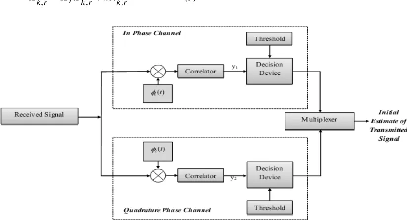
c) Receiver section
Figure 4: Block Diagram Of The Receiver Section
Thereceived signal at the
i
threceived antenna forthe
k
th OFDM symbol and ther
thsub-carriercan be represented as:) 8 (
. (,)
0
) (
, ) , ( )
( ,
i r k nr
j
j r k j i o i
r
k h f noi
x =
∑
+=
) , ( ji o
h
is the channel parameter from the thj
transmitting antenna to thei
threceiving antenna which composes the MIMO channel matrix. The received signal can also re-written as (by removing the index values):) 9 (
. , ,
,r r k r kr
k H F noi
X = +
Where, nr T
r k r k r
k x x
X [ ,.., ( 1)] , ) 0 (
, ,
−
= and
th
j
i
,
)
(
element ofH
r is:h
(i,j)m;The received signal is initially taken FFT and demodulated withQPSK demodulator. Let the Let
1 1
0
,
X
,...,
X
M−X
represent the received signal, and then FFT is given by:)
10
(
1
0
2
∑
−= −
=
Mm
M m k i m
k
X
e
Y
πAfter taking FFT, hard decision decoding is carried on spatial dimension with the use of QPSK demodulation.
[image:6.612.98.510.454.677.2]FFT transformed signal is subsequently demodulated with the QPSK demodulator as shown in figure 5. The FFT transformed signals are initially multiplied with the orthonormal functions
(
φ
1(
t
)
andφ
2(
t
)
) and are given to the respective correlators. The correlator output signals(
y
1and
y
2)
are compared with the threshold set (which is zero) and hard decisions (0 or 1) are taken depending on the criteria fulfilment given in table 1.Table 1: Hard decision decoding table on first spatial dimension using QPSK
Channel Criteria Decision taken
In-phase
0
1
>
y
1In-phase
0
1
<
y
0Quadrature
phase
y
2>
0
1
Quadrature
phase
y
2<
0
0
Subsequently twodecision outputs are pooled using a multiplexer to have the initial estimate of the original signal.The QPSK demodulation results
in the signals represented
by
Z
k,r=
[
z
k(0,r),..,
z
k(nr,r−1)]
T, which is taken forfurther processing.
Auxiliary symbol vectors are constructed from
QPSK demodulated signals
z
k as in the equation:) 11 ( . ~ k k Iz z =
where
I
is the identity matrix. Receive vectors are formed fromthe auxiliary symbol vectors by equation given by:) 12 ( 0 , ~ .
~x x H z j M
j
j= − ≤ <
This equation forms the parallel interference cancellation equation. In order to improve on the results and decreasing the bit error rate, we employ Bayesian probability measure. This is done by incorporating Bayesian probability equation into the equation 12. The modified equation is given by:
) 13 ( ~ . . ~ ~ 1 0 ∗ =
∑
− = M z H x x x M j j j jThe obtain values are subsequently done hard decision decoding to have the transmitted signal values. The threshold is set as zero, and the criteria for decision making are given in table 2:
Table 2: Hard Decision Table For Received Signals
Criteria Decision value
0
~
>
jx
10
~
≤
jx
oLet the final decision values be represented
as
W
=
{
w
j}
;
where
0
≤
j
<
M
. The error canbe calculated as the difference in original signal transmitted and the final decoded signal given by:
) 14 ( 0
, ≤ < =
∑
−
= j j j
j g w j M and E e e
The total error can be computed as the summation of individual errors. Use of Bayesian probability to the parallel interference cancellation equation has resulted in successfully cancelling the interference and hence, lowering the bit error rate and improving the reception.
4. RESULTS AND DISCUSSIONS
In this section, the analysis and the results of the proposed BPICI cancelleris given. Comparative analysis is also made comparing the performance of our proposed technique to other prominent techniques. Analysis is carried out with the help of Bit Error Rate curves. Section 4.1 describes the experimental set-up employed and in section 4.2, we make a detailed analysis is carried out.
4.1 Experimental Set Up
The proposed BPICI cancelleris implemented in MATLAB Version 2012 on a system having 8 GB RAM with 64 bit operating system having i7 Processor. For evaluation purpose, we make of randomly generated signals in MATLAB.
4.2 Performance Analysis
The Bit Error happens when the received bits of the data stream over a communication channel differs from the transmitted signals. This happens due to alteration of the signal which may occur due to the interference of unwanted signals, noise effects, distortions or bit synchronization errors, multipath fading, attenuation. The bit error rate or bit error ratio (BER) is the ratio of bit errors to the total transferred bits during the specified time interval. BER is performance measure used for evaluating the performance or the functionality of various methods and systems. BER plot can infer
the performance of the system. o N
Eb is the energy
received signal. o N
Eb is basically a normalized
signal-to-noise ratio (SNR) measure of the signal.
We consider the system for both the Rayleigh and Ricianchannel independently and plot BER curves for both. Rician fading is a stochastic model for radio propagation anomaly caused by partial cancellation of a radio signal by itself — the signal arrives at the receiver by several different paths and at least one of the paths is changing. Rician fading occurs when one of the paths, typically a line of sight signal, is much stronger than the others. In Rician fading, the amplitude gain is characterized by a Rician distribution [19].
Comparative analysis is made with respect to other prominent techniques of Parallel Interference Cancellation and Minimum Variance Distortionless Response (MVDR).The analysis is made in two parts, first by varying the number of antennas and in the second part, length of the user input signal is varied. In both parts the results are taken for Rayleigh and Rician channel independently.
Part 1. Effects on the performance of the proposed system by varying the number of antennas:
[image:8.612.326.505.80.232.2]The number of antennas is varied and BER curve is plotted in each case in this section. Results for Rayleigh and Rician channel are taken independently.
[image:8.612.331.500.260.396.2]Figure 6: BER Curve For N=2 And Rayleigh Channel Is Used
[image:8.612.325.508.433.587.2]Figure 7: BER curve for N=2 and Rician channel is used
Figure 8: BER Curve For N=3 And Rayleigh Channel Is Used
Figure 9: BER Curve For N=3 And Rician Channel Is Used
Observations from figures 6-9: • BER curves (BER vs.
o N
Eb ) are plotted for
[image:8.612.103.280.448.589.2]plotted for proposed BPIC, PIC and MVDR techniques.
• The number of user signal input is fixed for for N=2 and 99999 for N=3.
• Figure 6 and figure 8 gives the BER graph obtained for N=2 and N=3 respectivelyfor Rayleigh channel.
• Figure 7 and figure 9 gives the BER graph obtained for N=2 and N=3 respectively for Rician channel.
• From the results, we can see that our proposed BPCI had achived lower BER curves which shows the effectiveness of the technique. Proposed BPCI has attained lower BER when compared with PIC and MVDR.
• The BER curves obatined proves the validity of the technqiue.
Part 2. Effects on the performance of the proposed system by varying the length of the user input signal
[image:9.612.317.509.102.447.2]The length of the user signal (represented by K) is varied and corresponding BER curve is plotted in each case in this section. Results for Rayleigh and Rician channel are taken independently.
Figure 10: BER Curve For K= And Rayleigh
Channel Is used
Figure 11: BER Curve For K= And Rayleigh Channel Is Used
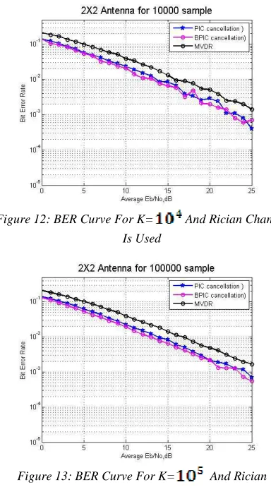
Figure 12: BER Curve For K= And Rician Channel Is Used
Figure 13: BER Curve For K= And Rician Channel Is Used
Observations from figures 6-9:
• The BER curves are plotted by varying the length of the user input. Both Rayleigh and Rician fading channels are considered independently. • BER curves are plotted for proposed BPIC, PIC and MVDR techniques.
• Curves are plot for two cases in each channel for K=104 and K=105.
• Figure 10 and 11 gives BER curve for Rayleigh channel for K=104 and K=105 respectively.
• Figure 12 and 13 gives BER curve for Rician channel for K=104 and K=105 respectively.
• From the results, we can see that our proposed BPCI had achived lower BER curves when compared with PIC and MVDR.
• Lower BER means that the proposed technqiue has performed well.
5. CONCLUSION
[image:9.612.104.313.377.722.2]this paper. Signals are transmitted, which propagate through the channel and is received by the receiver section. In receiver, hard decision based decoding, parallel interference cancellationand Bayesian probability is employed. The technique is implemented in MATLAB and usesBER curves as evaluation metrics. Various curves are obtained by varying the fading channel, number of user signals and number of antennas.The fading channel considered are the Rayleigh and the Rician fading channel. Experimentation is carried out for antenna size = 2 and 3.Comparative analysis is also made by comparing to other techniques such as PIC and MVDR. From the results, we can see that our proposed technique has achieved better performance by having lower BER.
REFERENCES
[1] Chao-Wang Huang, Pang-An Ting, and Chia-Chi Huang, "A Novel Message Passing Based MIMO-OFDM Data Detector with a Progressive Parallel ICI Canceller", IEEE transactions on wireless communications, Vol. 10, No. 4, April 2011.
[2] Pankaj Kumar Sharma, Chhavi Sharma, S.K.Tomar and A.K.Gupta, “PAPR Reduction in MIMO-OFDM systems using new PTS”, MIT international Journal of Electronics and Communication Engineering, Vol. 1, No. 2, pp.83-87,2011.
[3] Hoa Tran, “A Method in Computing Successive Interference Canceller”, Journal of Wireless Networking and Communications, Vol.2, No.3, pp.11-13, 2012.
[4] Hang Long, Kyeong Jin Kim, Wei Xiang, ShanshanShen, KanZheng, and Wenbo Wang, “Improved Wideband Precoding with Arbitrary Subcarrier Grouping in MIMO-OFDM Systems”, ETRI Journal, Vol. 34, No. 1, pages 9-16, February 2012.
[5] Yechang Fang, Yu Du, Kang Yen, Nansong Wu, “Blind Multiuser Detection in SDMA-aided
MIMO OFDM Systems by FastICA
Algorithm”, International Journal of Computer Science and Information Security, Vol.8, Pages. 1-5, 2010.
[6] Xu, Peng, Wang, Jinkuan, Qi, Feng, “Improved H-infinity channel estimator based on EM for MIMO-OFDM systems”, Journal of Systems Engineering and Electronics, Vol.22, No. 4, Pages. 572 – 578, 2011.
[7] Karima El Mouhib, Ahmed Oquour, YounesJabrane, Brahim Ait Es Said and Abdellah Ait Ouahman, “PAPR Reduction Using BPSO/PTS and STBC in MIMO OFDM
System”, Journal of Computer Science, Vol. 7, No.4,pp. 454-458, 2011.
[8] J. Mitola, "The software radio architecture", IEEE Communication Magazine, Vol.33, pp.26-38,1995.
[9] J A Wepman,. "Analog to digital converters and their application in radio receivers", IEEE Communication Magazine, Vol.33, pp.46-54,1995.
[10] Nghi H. Tran, “Signal Mapping Designs for Bit-Interleaved Coded Modulation with Iterative Decoding (BICM-ID),” Thesis, Department of Electrical Engineering, University of Saskatchewan, December 2004.
[11] Oyerinde and OlutayoOyeyemi, "Channel estimation for SISO and MIMO OFDM communications systems," 2010.
[12] PramodViswanath and Cambridge, “Fundamentals of Wireless Communications,” University Press, May 2005.
[13] A. Falsafi, K. Pahlavan, and G. Yang, “Transmission technique for radio LAN’s—a comparative performance evaluation using ray tracing,” IEEE J. Select. Areas Commun., vol. 14, pp. 477–491,1996.
[14] Eric Philip Lawrey, ‘‘Adaptive Techniques for Multi-users OFDM’’, James cooks University, December 2001.
[15] A. J. Paulraj and T. Kailath, “Increasing Capacity in Wireless Broadcast Systems Using Distributed Transmission/Directional Reception”, U.S. Patent, no. 5,345,599, 1994. [16] G. J. Foschini, “Layered Space-time
Architecture for Wireless Communication”, Bell Labs Tech. J., vol. 1, pp. 41–59, 1996. [17] H. Bolcskei, D. Gesbert, A. J. Paulraj, “On the
Capacity of OFDM-Based Spatial Multiplexing Systems”, IEEETrans. Commun., vol. 50, no. 2, pp. 225–34, 2002.
[18] Bernard Skla, "Rayleigh Fading Channels in Mobile Digital Communication Systems Part I: Characterization". IEEE Communications Magazine, Vol.35, No 7, pp.90–100, 1997. [19] Abdi, A. and Tepedelenlioglu, C. and Kaveh,