Technology (IJRASET)
©IJRASET 2015: All Rights are Reserved
274
Automatic Voltage Regulator and Automatic Load
Frequency Control of Electrical Power Plant with
Optimal Tuning Controller PID
Ashok singh 1, Rmeshwar singh 2, Rekha kushwah3
Abstract— — this paper deals with an optimal tuned of without controller, Proportional Integral Derivative (PID) controller and Ziegler-Nichols tuned controller for both Automatic Voltage Regulation (AVR) and Load Frequency Control (LFC). As voltage constancy and frequency are important factors in determining the quality of power supply, the control of active power and reactive power is vital to the satisfactory performance of power system. The real power and frequency is controlled by LFC and the reactive power and voltage is controlled by AVR. Various measuring indices settling time, peak amplitude is considered as the performance measures for analyzing the transient response of AVR and LFC.The simulation results of the proposed Ziegler-Nichols tuned with compared PID tuned and without tuned controller. The comparative analysis clearly reveals that the transient response and the robustness are much improved with the proposed Ziegler-Nichols tuned approach over others..
Index Terms— Automatic Voltage Regulator, Automatic Load frequency control, PID controller, optimal Tuning, matlab simulink
I. INTRODUCTION
In recent years, the performance of computers has a great influence over the power systems in maintaining quality and Reliable power supply. Also the power system can be controlled easily and efficiently with higher degree of reliability. The growth in size and complexity of electric power systems along with increase in power demand has initiated the need for intelligent systems that combine different techniques and methodologies. The intelligent systems possess human like expert knowledge and adapt themselves in changing environments. In electric power system, as the demand deviates from its normal value with an unpredictable small amount, the state of the system changes. The automatic control system detects these changes and initiates in real time as set of control actions which will eliminate as effectively and quickly as possible the state deviations. The active and reactive power demands are never steady they continuously change with rising and falling trend[1].In a power system, load frequency control (LFC) and Automatic voltage regulator (AVR) plays an essential role to allow power exchanges and regulate generator voltages for consumers. LFC in a power system can boost the system performance and bring stability on frequency or voltages. LFC in power system is very important in order to supply reliable electric power with good quality and the goal is to reduce the steady state error to zero in a interconnected power system [2]. A good quality of the electric power system requires both the frequency and voltage to remain at standard values during operation. It will be impossible to maintain the balances of both the active and reactive power without control. As a result of the imbalance, the frequency and voltage levels will be varying with the change of the loads. Thus, a control system is essential to cancel the effect of the random load changes and to keep the frequency and voltage, at standard values [3].During the last decades the researchers have more attention to LFC over AVR although the main objective of the control strategy in an interconnected power system is, to generate both voltage and frequency within permissible limits. Recently, lot of research works were documented with an improved transient response by designing proper coupling effects between LFC and AVR and hence proves the necessity of AVR along with LFC. The flows of active power and reactive power in a transmission network are fairly independent of each other and hence this paper deals with individual control mechanism for LFC and AVR in order to improve the transient stability of power system [4][5].
II. BASIC OF AVR AND LFC CONTROL LOOPS
Technology (IJRASET)
specified limits. Small changes in real power are mainly dependent on changes rotor angle δ and, thus, the frequency f. The
reactive power is mainly dependent on the voltage magnitude (i.e. on the generator excitation). Change in angle δ is caused by
[image:3.612.141.472.179.316.2]momentary change in generator speed. Therefore, load frequency and excitation voltage controls are non-interactive for small changes and can be modeled and analyzed independently. Furthermore, excitation control is fast acting while the power frequency control is slow acting since, the major time constant contributed by the turbine and generator moment of inertia-time constant is much larger than that of the generator field. Thus, the cross-coupling between the LFC loop and the AVR is negligible, and the load frequency and excitation voltage control are analyzed independently [6].
Fig 1 Schematic diagram of LFC and AVR of a
III. AVR MODELING
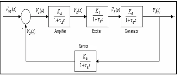
The role of an AVR is to hold the terminal voltage magnitude of a synchronous generator at a specified level. A simple AVR system comprises four main components, namely amplifier, exciter, generator, and sensor. The Basic Diagram of AVR Systems show in the fig 2, For mathematical modeling and transfer function of the four components, these components must be linearized, which takes into account the major time constant and ignores the saturation or other nonlinearities. The reasonable transfer function of these components may be represented, respectively; the generator excitation system maintains generator voltage and controls the reactive power flow using an automatic voltage regulator (AVR). The role of an AVR is to hold the terminal voltage magnitude of a synchronous generator at a specified level. Hence, the stability of the AVR system would seriously affect the security of the power system [7]
Fig 2 Basic Diagram of AVR systems
A simpler AVR system contains five basic components such as amplifier, exciter, generator, sensor, and comparator. Model and the Basic Diagram of AVR system show in Fig 1. In the comparator. Later on, the error voltage obtained from the output of the comparator amplified in the amplifier and applied to the controller. Consequently, the output of the controller used in order to control the generator field winding by way of the exciter
IV. MODELING OF SINGLE AREA SYSTEM LOAD FREQUENCY CONTROL (LFC)
[image:3.612.153.462.476.606.2]Technology (IJRASET)
©IJRASET 2015: All Rights are Reserved
276
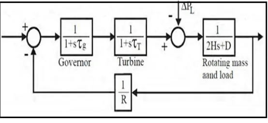
demand changes, a frequency change occurs. This frequency error is amplified, mixed and changed to a command signal which is sent to turbine governor. The governor operates to restore the balance between the input and output by changing the turbine output. This method is also referred as Megawatt frequency or Power-frequency (P-f) control [8].An isolated electric area, where one generating unit or bunch of generating units, is placed in close vicinity to distribute the electricity in the same area is called single area system. More than one control area power systems with a single control zone is actually a combination of power systems and the problems of each region, combining a control structure. Fig 3 is a single zone with a power system block diagrams. Here, the system, a regulator regulating the speed of synchronous generator, synchronous generator and the load is composed. Only the generating unit present in that area is responsible to maintain the desired frequency in normal and abnormal conditions [9].Load Frequency Control (LFC) can be defined as an ancillary service that is related to the short-term balance of energy and frequency of the power systems and acquires a principal role to enable power exchanges and to provide better conditions for electricity trading [10].
The main objectives of Load Frequency Control (LFC) are: Ensuring zero steady-state error for frequency deviations.
Minimizing unscheduled tie line power flows between neighboring control areas. Getting good tracking for load demands and disturbances.
[image:4.612.168.445.309.436.2]Maintaining acceptable overshoot and settling time on the frequency and tie line power deviations.
Fig 3 Basic Diagram of AVR systems
Extraction from the system, as a result declining of system frequency occurs. As the frequency gradually decreases, power consumed by the old load also decreases. In case of large power systems the equilibrium can be obtained by them at a single point when the newly added load is distracted by reducing the power consumed by the old load and power related to kinetic energy removed from the system. Definitely at a cost of frequency reduction this equilibrium is achieved. The system creates some control action to maintain this equilibrium and no governor action is required for this. The reduction in frequency under such condition is very large.
V. CONTROL AND ESTIMATION TOOLS MANAGER
Technology (IJRASET)
VI. ZIEGLER NICHOLS TUNING METHOD
The most popular tuning methodology was proposed by Ziegler and Nichols in 1942. PID controller‘s on line auto tuning that is based on Ziegler Nichols tuning method. The advantage of Z-N PID controller tuning is also carry out for higher order systems [12]. Z-N PID Controller is controlling the plant or system by continuously monitoring plant output which is known as process value with the desired process value known as set point of the system [5]. The PID controller manipulates on the difference between process value and set point called as error. In the conventional controlling method the transfer function of plant should be calculated in order to find out various parameters and the value of PID constants. But in this method there is no necessary to derive the transfer function of the system. Thus Z-N PID controller is monitoring the plant depending on set point and process value and irrespective of the nature of plant.
VII. .RESULT ANALYSIS OF AVR SYSTEM AND LFC
In this paper analysis of single area power system with, without controller, PID and Z-N tuning controller and Power plant MATLAB Simulink model design for AVR system and LFC. The simulations results demonstrate the effectiveness of the designed system in terms of reduced settling time, overshoot and oscillation. All results analysis using control system tool using Z-N tuning algorithm and simulated by MATLAB (R2010a) software. An isolated power station has the following parameter [2] in the appendix section.
A. Test System 1. Control Of Automatic Voltage Regulator
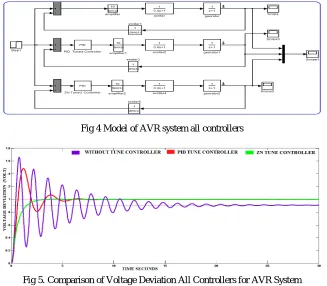
[image:5.612.144.471.392.678.2]In this case comparative analysis with without controller tuned, PID tuned controller and ZN tuned controller show simulink model fig 4.Response of AVR system settling time is 19.1 without controller tuned, 5.49 is PID tuned controller and settling time 2.42 is ZN tuned controller shown in the fig 5, show the effectiveness of the proposed approach ZN tuned controller, It is clear from the fig that Settling time also reduced compared to without tuned controller, PID tuned controller (PID) controller respectively. The above analysis clearly reveals the superiority of the proposed ZN tuned controller for AVR system compared to other approaches
Fig 4 Model of AVR system all controllers
Fig 5. Comparison of Voltage Deviation All Controllers for AVR System
B. Test System 2 Load Frequency Control
Technology (IJRASET)
©IJRASET 2015: All Rights are Reserved
[image:6.612.144.471.125.417.2]278
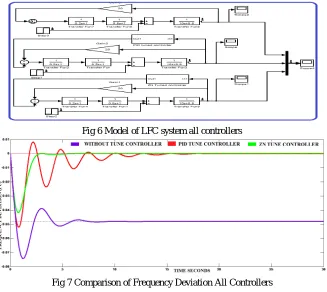
in the fig 6. Combined Simulation results show without tune Controller, PID tuned Controller and ZN tuned Controller in the fig 7.The results of proposed ZN tuned controller are compared without tune Controller, PID tuned Controller and ZN tuned Controller enforced to the load frequency control power system. The proposed approach ZN tuned Controller is better the other controllerFig 6 Model of LFC system all controllers
Fig 7 Comparison of Frequency Deviation All Controllers
VIII. CONCLUSION
The MATLAB simulations results show that the proposed ZN Tuned controller is more effective means for improving the dynamic performance of the AVR and LFC .compared to the compared PID tuned and without tuned controller. The proposed controller still achieves good dynamic performance when the other controller such as PID Controller and without controller response. The simulation results show that the proposed controller can perform an efficient search that achieves better performance criterion through also, the ZN tuned controller response is more superior.
REFERENCES
[1]A. Soundarrajan1, S. Sumathi2 and G.Sivamurugan3, “Hybrid Evolutionary Algorithms For Frequency And Voltage Control In Power Generating System” A. SOUNDARRAJAN et. al.: Hybrid Evolutionary Algorithms For Frequency And Voltage Control In Power Generating Station 2010.
[2]Dr.B.U.Musa1, Kalli .B.M.2, Kalli Shettima3, “Modeling and Simulation of Lfc and Aver with Pid Controller,” International Journal of Engineering Science Invention, Volume 2 Issue 7 ǁ July. 2013 ǁ PP.54-57.
[3]Anbarasi S#1, Mur alidharan S*2 , “Transient Stability Improvement Of LFC And AVR Using Bacteria Foraging Optimization Algorithm”, International Journal of Innovative Research in Science, Engineering and Technology Volume 3, Special Issue 3, March 2014 2014 IEEE International Conference on Innovations in Engineering and Technology (ICIET’14)
[4]Ahmad M. Hamza, Mohamed S. Saad, Ahmed Bahgat, “Design of LFC and AVR for single area power system with PID controller tuning by BFO and Ziegler Methods,” International Journal of Computer Science and Telecommunications, vol. 9, issue 5, pp. 12-17, May 2013.
[5]Saumya Kr. Gautam, Nakul Goyal, “Improved Particle Swarm Optimization Based Load Frequency Control In A Single Area Power System”, 2010 Annual IEEE India Conference (INDICON), 978-1-4244-9074-5/10/$26.00 ©2010 IEEE.
[6]A.Soundarrajan, Member, IAENG, Dr.S.Sumathi, C.Sundar, “Particle Swarm Optimization Based LFC and AVR of Autonomous Power Generating System”, IAENG International Journal of Computer Science, 37:1, IJCS_37_1_10.
[7]H. Yoshida, K. Kawata, and Y. Fukuyama, “A particle swarm optimization for reactive power and voltage control considering voltage security assessment,” IEEE Trans. Power Syst., vol. 15, pp. 1232–1239, Nov. 2000.
[8]A.Soundarrajan, Member, IAENG, Dr.S.Sumathi, C.Sundar, “Particle Swarm Optimization Based LFC and AVR of Autonomous Power Generating System” IAENG International Journal of Computer Science, 37:1, IJCS_37_1_10.
[9]Zwe-Lee Gaing, “A particle Swarm Optimization approach for optimum design of PID controller in AVR system”, IEEE Transactions on Energy Conversion, Vol.19, No.2, 2004, pp384-391.
Technology (IJRASET)
Frequency Control Problem” International Journal of Advanced Research in Electrical, Electronics and Instrumentation Engineering, Vol. 3, Issue 11, November 2014.
[11] www.mathworks.com/control-system-toolbox.
[12] Bhaskar Lodh, “Simulink Based Model for Analysing the Ziegler – Nichols Tuning Algorithm as applied on Speed Control of DC Motor” International Journal of Advanced Research in Electrical, Electronics and Instrumentation Engineering,Vol. 3, Issue 1, January 2014.
[13] Rajeev Kumar1, Sunil K. Singla2, Vikram3, “A Comparative Analysis of different Methods for the tuning of PID Controller”, International Journal of Electronics Communications and Electrical Engineering ISSN : 2277-7040 Volume 3 Issue 2 (February 2013)
[14] Rajkumar Bansal1, A.Patra2, Vijay Bhuria3, “ Design of PID Controller for Plant Control and Comparison with Z-N PID Controller”, International Journal of Emerging Technology and Advanced Engineering Website: www.ijetae.com (ISSN 2250-2459, Volume 2, Issue 4, April 2012
APPENDIX
NAME OF PARAMETER GAIN TIME CONSTANT
Turbine KT=1 Tt=0.5
Governor Kg=1 Tg=0.2
Governor Ka=10 Ta=0.1
Exciter Ke=1 Te=0.4
Generator Ka=0.8 Ta=1.4
Sensor Kr=1 Tr=0.05
Inertia H=5