Analysis of Multiband S-Shaped Microstrip
Antenna for Wireless Communication
Priyank Nautiyal1, Pankaj Agarwal2, Satyendra Srivastav3
1
P.G Scholar, Shobhit University, Meerut,U.P
2
Assistant Professor, JP Institute of Engg.& Tech.,Meerut,U.P.
3
Assistant Professor, Shobhit University, Meerut,U.P
Abstract—In this research paper a S-Shaped multi frequency antenna is designed. The S-Shaped patch is obtained from
conventional rectangular patch by using a rectangular slot. The antenna is excited by the use of simple probe feed. This antenna has a very simple and compact structure and thus is easy to be fabricated. The proposed antenna is operating at 1.7 GHz, 3.1 GHz, 4.15 GHz and 4.9 GHz .The design frequency of antenna is 2.05 GHz. Zeland IE3D software is used for simulation of proposed design .
Keywords— S-Shaped, Patch antenna, VSWR, Gain, Multiband
I. INTRODUCTION
In modern era, a microstrip antenna is very extensively used as it has many qualities which put it above other type of antennas , in the preference list for use. Those qualities are that, a microstrip patch antenna has a very small size, light weight, easy to fabricate, low cost. Due to these qualities, it has an edge over other type of antennas. The microstrip patch antenna has a radiating patch, a dielectric substrate and a ground plane. The patch is made up of a conducting material. The reason due to which microstrip patch antenna radiate is the presence of fringing fields between the patch edge and the ground plane. Different results are obtained after simulating the result, which eventually helps to find gain, directivity, antenna efficiency, bandwidth.
Microstrip antenna is generally used for many wireless applications due to light weight and patch can be of any shape. Patch is generally made of material such as copper or gold. In radar and satellite communication, it is necessary to design antennas with very high directive characteristics to meet the demand of long distance communication. They have the capability to operate in dual and triple band frequency operations . The patches are the basic and most commonly used Microstrip antennas. These patches are used for the simplest and the most demanding applications.
An antenna is the most important element of any wireless communication. The S -shaped Multiband Microstrip Patch antenna is simulated and analyzed using IE3D. This antenna is designed for various multiple applications such as Bluetooth, Medical Application and ISM Application, in the operating range 1-5 GHz. A compact analysis and design of S-shaped Microstrip patch antenna suited for Wi-max application is simulated over IE3D software. The obtained gain and bandwidth is best suited for Wi-max application. A wideband S-shape microstrip patch antenna is designed. The bandwidth is further increased by introducing PBG structure. The antenna designed by this method has low volume and low profile configuration, easily mounted, low fabrication cost and light weight. This antenna is best suited for S-band communication. The study of microstrip patch antennas has made great progress nowadays. The microstrip patch antennas can provide dual and circular polarizations, dual frequency operation, frequency agility, broad band-width, feed line flexibility, beam scanning omnidirectional patterning. In this paper the microstrip antenna, feeding technique and results obtained from a microstrip patch antenna are discussed in detailed form. The S-shaped Microstrip Patch Antenna is used in place of simple rectangular antenna because the surface area of former is much less than that of later, which eventually leads to better results and desired graphs.
II. FEEDING TECHNIQUES
Technology (IJRASET)
III.ANTENNA DESIGN
The figure shows the geometry of the S shaped microstrip patch antenna. To get a S shaped antenna , first of all a microstrip antenna of rectangular shape is designed according to the dimensions , which are given for length and width then S-shaped antenna’s boundary’s are drawn , and then it is cut down by the boundary of the proposed s shaped antenna , whose boundaries have been earlier drawn by us , in order to get the desired shaped antenna . The material used for antenna comprise of copper patch and FR4 epoxy substrate.
The dimensions of the ground plane are 35mm*40mm . A single-patch broadband microstrip S-shaped patch antenna fed by a coaxial probe feeding is then simulated and designed using IE3D software. This antenna is operating at centre frequency of 2.05 GHz.
IV.DESIGN SPECIFICATIONS
Length of Rectangular Patch (L)- 35 mm Width of Rectangular Patch (W)- 40 mm Substrate’s Thickness -1.6mm Dielectric Constant -4.3 Feed Point Location - (8.6,10)
Step 1: Calculation of the Width (W): The width of the Microstrip patch antenna is given by
2 ) 1 ( 2 0 r f c W eq.1
Step 2: Calculation of Effective dielectric constant (ε reff ):
2 1 12 1 2 1 2 1 w h r r eff eq.2 Step 3: Calculation of the Effective length (Leff ):
eff eff f c L
0 2 eq.3 Step 4: Calculation of the length extension ( ΔL): 8 . 0 ) 258 . 0 ( 264 . 0 ) 3 . 0 ( 412 . 0 h W h W h L eff eff eq.4 Step 5: Calculation of actual length of patch (L ):
L L L eff2
eq.5
Step 6: Calculation of the ground plane dimensions ( Lg and Wg ):
Fig.1. Geometry of S-Shaped Microstrip Antenna
[image:4.612.184.428.324.466.2]V. SIMULATION RESULTS AND DISCUSSION
Fig. 2. S Parameter vs Frequency Curve
The return loss of the design shows that it has four resonance within the frequency band under observation. The value of first resonance is -16 dB at 1.85 GHz, second resonance is -25 dB at 3.1 GHz , -24 dB at 4.15 GHz and -18.7 dB at 4.9 GHz. Since the antenna is designed at 2.05 GHz and the first fundamental resonance is shifted towards left, therefore the antenna miniaturization is achieved by using a S-shaped antenna rather than a conventional rectangular patch.
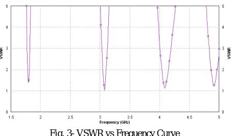
Fig. 3- VSWR vs Frequency Curve
The VSWR of the design shows that it has four resonance within the frequency band under observation. The value of first resonance is -1.4 dB at 1.7 GHz , second resonance is -1 dB at 3.1 GHz , third resonance at -1.1 dB at 4.15 GHz and fourth resonance at –1.2
L=35mm
L= 18 mm L= 8 mm
L= 18 mm L= 8 mm
L= 6 mm
L= 6 mm
[image:4.612.194.421.537.670.2]Technology (IJRASET)
Fig, 4 – Gain vs Frequency Curve
[image:5.612.203.381.276.462.2]In the graph representing Gain vs Frequency , we analyse that the maximum gain is obtained as 3.9 dB at 10.6 GHz .
Fig. 5 – Radiation Pattern of the Antenna
Fig. 6 – Current distribution on the Antenna
VI. CONCLUSION
[image:5.612.193.421.493.655.2]The proposed antenna can be used for Wireless Communication.
REFRENCES
[1]. Islam Mohammad Tariqul, Shakib Mohammad Nazmus, Misran norbahiah, “ High Gain Microstrip Patch Antenna”, European journal of Scientific Research ISSN 1450-216X Vol. No. 2(2009), pp 187-193.
[2]. Sharma Aditi, Dwivek Vivek K., Singh G., “THz Rectangular Microstrip Patch Antenna on Multilayered Substrate for Advanced Wireless Communication system”, Progress in electromagnetic research symposium, Beijing China, March 23-27,2009.
[3]. Ali Jawad K., “A New Compact Size Microstrip Patch Antenna with Irregular slots for Handheld GPS applications”, Engg. & Technology, Vol. 26 No. 10, 2008.
[4]. Ali M., Dougal R., Yang G., Hawang H.S., “Wideband circularly Polarized Microstrip Patch Antenna for wireless Lan Applications”.
[5]. Singh Amit Kumar, Meshram Manoj Kumar, “Slot Loaded Shortd patch For Dual Band Operation”, Microwave and Optical Technology Letters/Vol. 50, No. 4, April 2008.
[6]. B.K. Ang, B.K. Chung, “A Wideband E-Shaped Microstrip Patch Antenna For 5–6ghz Wireless Communications,” Progress In Electromagnetics Research, Multimedia University, Cyberjaya, Malaysia PIER 75, pp. 397–407, 2007.
[7]. X.L. Bao and M.J. Ammann “Small patch slot antenna with 53% input impedance bandwidth,” Electronics Letters, Vol. 43 No. 3, February 2007.
[8]. M. Aminah, N. Saman, and H. A. “Simulation and Design of Wide-Band Patch Antennas for Wireless Technology,” International Engineering Islamic University Malaysia, Proc. ‘EuCAP’, Nice, France, November 2006.
[9]. M.A. Matin, B.S. Sharif, C.C. Tsimenidis, “Microstrip patch antenna with matching slots for UWB communications,” International Journal of Electronics & Communication, pp 132-134, AEU, DEC., 2005.
[10]. G. Rafi and L. Shafai, “Broadband microstrip patch antenna with V-slot”, IEE Proc. Microwave Antenna Propagation, Vol. 151, No. 5, 435–440, October 2004. [11]. G.W.M. Whyte* , N. Buchanan** , J. Thayne , consortium “An Omni-directional, low cost, low profile, 2.45 GHz microstrip fed rectaxial antenna for wireless
sensor network Applications,” *Glasgow university, **Queens university, Belfast, IEEE Conference, 2004.
[12]. M. Eunni, M. Sivakumar, Daniel D.Deavours, “A Novel Planar Microstrip Antenna Design for UHF RFID” Information and Telecommunications Technology Centre, University of Kansas, Lawrence, KS 66045.
[13]. K.L.Lau, K.M.Luk, K.F.Lee, “A patch antenna with rectangular loop feed”, IEEE Transactions on Antennas and Propagation, Vol.51, No.9, September 2003. [14]. K. F. Lee, “Experimental and simulation studies of the coaxially fed U-slots rectangular patch antenna,” IEE Proc. Microwave Antenna Propagation, Vol. 144,
No. 5, 354–358, October 1997.
[15]. M. Samsuzzaman and M.T.Islam, “Inverted S-Shaped compact Antenna for X-Band Applications”, The Scientific World Journal, Hindawi Publishing Corporation, 2014.
[16]. Shobhit K. Patel and Y.P. Kosta, “S-Shape Meandered Microstrip Patch Antenna Design using Metamaterial”, IEEE, 2014.
[17]. Nasimuddin, Zhi Ning Chen and Xianming Qing, “Dual-Band Circularly Polarized S-Shaped Slotted Patch Antenna With a small Frequency-Ratio”, IEEE Trans. On Antennas Propagation, Vol 58, No. 6,June 2010.
[18]. Naresh Kumar Joshi, Anoop Singh Poonia and Piyush Choudhary, “ Broadband Microstrip S-shaped Patch Antenna for Wireless Communication”,International Journal of Computer Applications Volume 57– No.17, November 2012.