6
I
January 2018
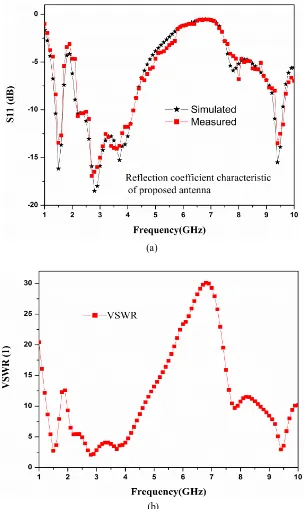
band with their impedance bandwidth of 18%, 72%, and 3.5% respectively. Both theoretical and experimental results for Return loss, VSWR, gain, and radiation characteristics are presented and discussed. The measured and simulated results presented show good agreement.
Keywords: Rectangular microstrip patch, parasitic elements, Bandwidth enhancement, Monopole antenna, Wide-band, CPW- Antenna, AWR.
I. INTRODUCTION
In recent years, the technology for multiple band operation and the bandwidth enhancement for wireless applications have developed very quickly [1].
Now days, the demand is compact wireless devices for multi- applications. This implies that the size of antennas should be small enough and the antenna operates at multi-band. For this purpose, patch antennas are suitable because of their light weight, low profile, simple structure, and ease of fabrication [2-3].
For multi-applications, the patch antenna suffers a problem of narrow bandwidth that can be solved by applying the wideband feeding techniques [4-6]. There are several feeding techniques like coaxial probe fed, microstrip line fed, edge fed, inset fed, CPW fed. In the proposed antenna, CPW feed is used due to its wide band characteristics and low VSWR [7-9].
In this paper, a T-shaped monopole patch antenna with CPW-fed technology including two symmetrical rectangular ground plane is proposed for WLAN applications. By adjusting the size of the spacing gap ‘g’ and feed line, the overall performance of the proposed antenna can be improved.
II. ANTENNA GEOMETRY AND PARAMETRIC STUDIES
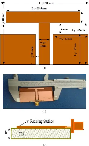
The geometry of the proposed T-shaped monopole patch antenna is shown in Fig. 1. The antenna has been designed using the rectangular T-shape patch in a monopole configuration. The monopole structure provides impedance matching over the wide range of frequency.
The proposed antenna is designed with the calculated dimension of the patch using finite element based electromagnetic simulator HFSSv.13 (High-frequency structure simulator) software. The proposed antenna is designed on single layer FR4 substrate of dimension (Ls*Ws = 50mm*40mm), thickness 1.6 mm, relative permittivity 4.4 and dielectric loss tangent of 0.002.
(a)
(b)
(c)
[image:3.612.159.454.78.560.2]Figure 1: (a) Geometry of the proposed antenna,(b) hardware of proposed antenna, (c) Side view of proposed antenna
Table 1
Parameters Values (mm)
Length of strip (monopole) (Ls=L+Lg)
31
Width of strip (monopole) (W) 3 Length of ground patch (Lg) 27 Width of ground patch (Wg) 22
Coupling gap (g) 0.5
(a)
(b)
[image:4.612.154.458.192.701.2]Figure 3. Gain of the proposed antenna
IV. PARAMETRIC STUDY
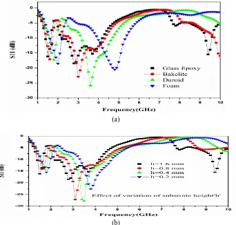
Figure 4(a) shows the parametric analysis of return loss by variation of dielectric constant of the substrate using different types of the substrate material. From the figure, it is seen that the double frequency band obtained at low dielectric constant (Foam).when the dielectric constant is increased the number of frequency band increased and also obtained the wide-band.
Figure 4(b) shows the parametric analysis of return loss by variation of the thickness of substrate material. The lower frequency band is shifted towards the lower frequency range when the thickness of substrate material increased. At a higher value of the thickness of substrate obtained the multi-band and also obtained the wideband at lower frequency band.
(a)
(b) Figure 4. (a) Simulated return loss vs frequency plot for different types of material of substrate of proposed antenna, (b) Simulated
[image:5.612.138.480.363.689.2]1 1
Fig.5(a)
1 1
Fig.5(b)
1 1
Fig.5(C)
Figure5.Current distribution at resonant frequency (a)1.5GHz(b)2.8GHz(c)9.4GHz
VI. RADIATION PATTERN
(a)
(b)
(d)
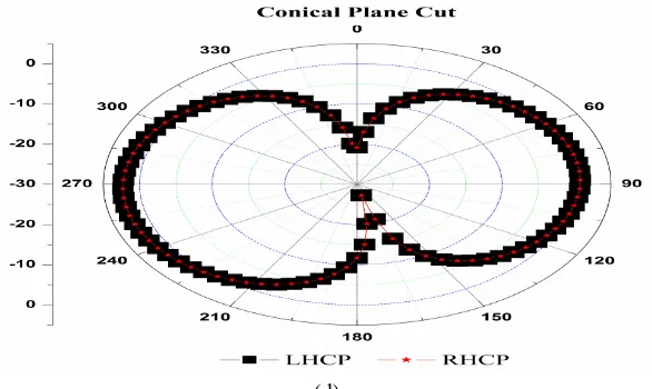
Figure 6. Radiation Pattern of Proposed Antenna: (a) Principle Plane Cut, (b) Conical Plane Cut, (C) Polarization in Principle Plane Cut and Conical Plane Cut, (d) Theta and Phi is fixed sweeps Frequency.
The Radiation Pattern of the proposed antenna is shown in figure-6. From the figure, it is clear that in principle plane cut when Theta is fixed at 0 degrees and Phi is varying give the information about cross polarization and co-polarization and calculating 3dB sartorial bandwidth about 88.6 degrees and gain around to be 1.739 dBi of total radiated power in the elevation plane. Conical plane cut Phi is fixed at 0 degrees and Theta is varying give the information about cross polarization and co-polarization for azimuth plane.When Theta and Phi are fixed sweeps Frequency that is a good agreement.
VII. CONCLUSIONS
The proposed antenna is based on CPW-Fed technique and provides the three resonating frequencies as 1.5GHz, 2.8GHz and 9.4GHz with an average gain of 2 dBi. The T-shape of the proposed antenna enhanced the impedance bandwidth of 2.8 GHz frequency band up to 72 %. Hence this compact microstrip antenna can be used for GPS antenna (1.5GHz), multichannel multi point distribution service (MMDS)WiMAX (2.8GHz) and X band (9.4 GHz)for radar applications. An optimization between size reduction and bandwidth enhancement is maintained in this work.
REFERENCES
[1] R. L. Li, B. Pan, T. Wu, J. Laskar, and M. M.Tentzeris "A Triple-Band Low-Profile Planar Antenna for Wireless Applications" December 15, 2008, IEEE Xplore. [2] R. K. Gupta "Printed TRI-BAND Monopole Antenna Structures For Wireless Applications" Issue 2, Vol I, Apr 2010.
[3] F. Yang, X. -X. Zhang, X. Ye, and Y. Rahmat-Samii,“ Wide-Band E-shaped Patch Antennas for Wireless Communications,” IEEE Trans. Antennas Propagat. vol. 49, no. 7, pp. 1094-1100, July. 2001.
[4] K. M. Luk, C. L. Mak, Y. L. Chow, and K. F. Lee, “Broadband microstrip patch antenna,” Electron. Lett., vol. 34, pp. 1442–1443, 1998 [5] H. W. Lai and K. M. Luk, “Wideband patch antenna with low cross polarization,” Electron. Lett., vol. 40, pp. 159–160, 2004
[6] K.M.Luk and H.Wong, “A new wideband unidirectional antenna element,” Int. J.Microw.Opt. Technol., vol. 1, no. 1, pp. 35–44, Jun. 2006.
[7] T.H. Kim and D.C. Park, “CPW-fed compact monopole antenna for dual-band WLAN applications,” Electronics Letters, Vol. 41, No. 6, 17th March 2005. [8] J.-W. Niu and S.-S. Zhong, “A CPW-fed broadband slot antenna with linear taper,” Microwave and Optical Technology Letters, vol. 41, no. 3, pp. 218–221, 2004. [9] J. Y. Sze and K. L.Wong, “Bandwidth enhancement of a microstrip line-feed printed wide-slot antenna,” IEEE Trans. Antennas Propag., vol. 49, no. 7, pp. 1020–
1024, Jul. 2001.
Authors
AKHILESH KUMAR PANDEY was born in Allahabad district of U.P. in 1983. He obtained his B.Sc. in Physics and Mathematics in 2004 from University of Allahabad. B.Tech. degree in Electronics & Communication Engineering in 2007and M.Tech. degree in Electronics Engineering in 2011 both from the Department of Electronics and Communication, University of Allahabad, Allahabad (U.P)-India. Currently he is pursuing D.Phil. degree from University of Allahabad. His research interests include antenna, simulation of RF devices and circuits and its applications.
E-mail: [email protected]
RAJEEV SINGH was born in Azamgarh district of U.P. in 1968. He received B.Sc. degree in 1989, B.Tech. in Electronics & Telecommunications in 1992, M.Tech. in Electronics Engineering in 1994 all from University of Allahabad. He obtained his D.Phil. degree in 2008 from University of Allahabad. He joined as Lecturer in the Department of Electronics and Communication, University of Allahabad, Allahabad (U.P)-India in 1996, became Sr. Lecturer in 2002, Reader in 2007 and Associate Professor in 2010. He has received German Academic Exchange Service Fellowship (DAAD) in the year 2003. He has worked for his D.Phil. research work during DAAD fellowship in the University of Potsdam, Germany from June 2003 to December 2004. He again visited University of Potsdam in the year 2008 under re-invitation program of DAAD. His area of research is charge storing polymers, polymer electronics, photo stimulated charge profile measurements, thermal diffusivity of polymers, Microwave and RF device and circuit simulation and its applications.