An Effective Design of Speed Controller for
Permanent Magnet Synchronous Motor Using
Fuzzy Technique
Ahamad Faras, Kapil Dev, M.Ayyub
Abstract: A permanent magnet synchronous motor (PMSM) features low inertia, high power density, low noise, high efficiency, low maintenance cost, and robustness, a PMSM has been widely used in many industrial applications. However, precise control of a PMSM is not easy due to nonlinearities of PMSM servo systems, parameter and load torque variations. Thus the linear control schemes such as PI control cannot guarantee satisfactory performances. In this paper a Simulink model of PMSM is derived from mathematical model. Then fuzzy model of PMSM is developed based on Takagi–Sugeno fuzzy approach, also a fuzzy speed regulator based on the Takagi–Sugeno fuzzy approach is designed for a PMSM. Simulation results are given to verify that the proposed method can be successfully used to control a PMSM under parameter and load torque variations.
Keywords: Fuzzy system, (PMSM), speed control, Takagi–Sugeno fuzzy model .
I. INTRODUCTION
A Permanent Magnet Synchronous Motor (PMSM) has low inertia, high power density, low noise, high efficiency, low maintenance cost, high torque density, and robustness. The permanent magnet synchronous motor eliminates the use of slip rings for field excitation, resulting in low maintenance and low losses in the rotor. Thus, a PMSM has been widely used in many industrial applications such as chip mount machines, semiconductor production machines, high-resolution computer-numerical-control machines, robots, and hard disk drives. But, precise control of a PMSM is not easy due to the nonlinearities of PMSM servo systems, parameter variations, and load torque variations. The main drawbacks of the linear control approach are the sensitivity in performance to the system parameters variations and inadequate rejection of external perturbations and load changes. Thus, the linear control schemes such as proportional–integral control cannot assure satisfactory performances. To remove this problem, many researchers have proposed various control design methods. e.g., neural network control [2], adaptive control [3][5], and
disturbance-observer-defining a fuzzy controller by rules with an obvious physical meaning has helped to expand this control technique. When it is applied to control nonlinear systems, this nonlinear control strategy has shown better results than classical controllers do.
II. PMSM MODEL
By taking the rotor coordinates of the motor as reference coordinates, a surface-mounted PMSM can be represented by the following nonlinear equation
V = (r + pL )i +ω L i +ω λ′ (1)
V = (r + pL )i −ω L i (2)
T = (λ′ i + (L − L )i i ) (3)
T = T + Bω + J. pω (4)
ω =ω
P denotes no. of poll and p differentiation.
By using equation 1 through 4, a surface-mounted PMSM can
be represented by the following nonlinear equation
ω∗ = k i − k ω − k T (5)
i ∗ = −k i − k ω + k V −ω i (6)
i ∗ = −k i + k V +ω i (7)
Where * denotes differentiation TLrepresents the load torque, ωr
is the electrical rotor angular speed, and ki > 0, i = 1 . . . 6, are
the parameter values given by k = λ , k = , k =
, k =
k =λL , k =L1
We want to design a T-S control system so a T-S model of
PMSM is required. In T–S fuzzy modeling n operating points
for a nonlinear system are first chosen, then a set of n simple
local linear subsystem models for each operating point is
obtained, and each subsystem model is associated with a fuzzy
inference rule. Based on the T–S fuzzy modeling approach, the
PMSM model can be approximated by a third order r-rule
fuzzy model. The ith rule of the T–S fuzzy model is of the
following form
Plant Rule i : If isis Fi, Then
ω∗ = k i − k ω − k T
i ∗ = −k i − k ω + k V −ω I i ∗ = −k i + k V +ω I
where Fi (i = 1, . . . , n) values denote the fuzzy sets, n is the
number of fuzzy rule, (Iqsi, Idsi) is the ithoperating point, and is=
[iqs, ids] T
. Each fuzzy set Fi is characterized by a membership
function mi (is) and the i th
operating point (iqs, ids) = (Iqsi, Idsi). By
using a standard T-S fuzzy inference mechanism, the following
global nonlinear model of PMSM can be obtained
ω∗= k i − k ω − k T (8)
i ∗ = −k i − k ω + k V − h (i )I ω
(9)
i ∗ = −k i + k V + h (i )I ω
(10)
where ℎ (·) = (·)/ (·), mi: R2→ [0, 1], i = 1,. . . ,
n is the membership function of the system with respect to plant rule i, hican be regarded as the normalized weight of each if–
then rule and satisfies mi(is) ≥ 0 and (·) = 1
Assuming two operating point such that Iqs1 = Iqs2 = I0, Ids1 =
−Ids2= I0and mi(is) are given by
m = µ( µ() µ)( )
m = 1 − m
Figure 1: q-axis T-S fuzzy model
Figure 2: d-axis T-S fuzzy model
These blocks are combined along with abc to d-q conversion block, to get complete fuzzy model of Permanent magnet synchronous motor.
III. FUZZY SPEED REGULATOR DESIGN
Let us define iqsd as iqsd = (k2ωd + k3TL)/k1, then by using
assumptions that va ‘TL is unknown and TL* can be neglected,
and it can be set as TL*= 0’, and the desired speed ωdis constant
and ωd
* = 0’, it
can be shown that i*qsd= 0. Taking ωandı as
ω=ω −ω andı = − i respectively.
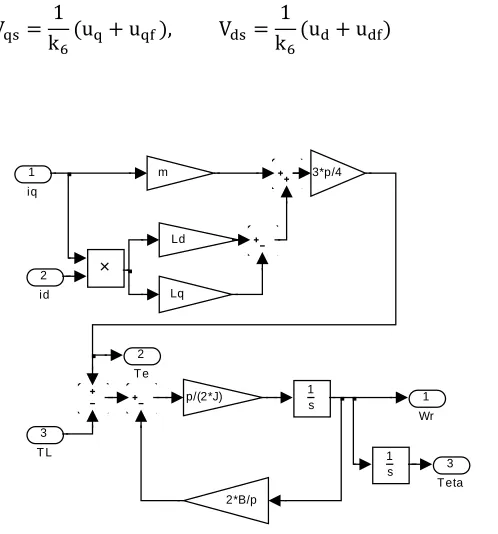
[image:4.612.298.547.119.386.2]V =k (u + u ),1 V =k (u + u )1
Figure 3: Torque and speed model
Then, fuzzy model can be transformed into
ω∗= k ı − k ω
ı ∗ = −k i − k ω + u + u − h (i )I ω
i ∗ = −k i + u + u + h (i )I ω Let the local speed
regulator be given by the following linear controller
Controller Rule i : If isis Fi, then
u = k x
Where = [ω, ı , ] uqdf= [uqf udf] T
, and Ki ∈R 2×3
are
gain matrices. Then, the final fuzzy speed regulator inferred as
the weighted average of the each local controller is given by
u = k i + k ω + h (i )I ω (11)
u = k i − h (i )I ω (12)
u = h (i ) k x (13)
[image:5.612.294.569.115.323.2]Simulink model for fuzzy speed regulator is given in figure 4.
Figure 4: Simulink model of Fuzzy speed regulator
IV. SIMULATION RESULT
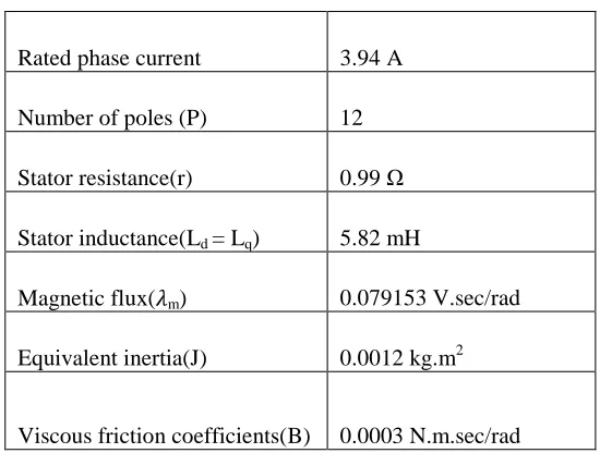
Table 1
Parameters Rating
Rated phase voltage 230 V
Rated phase current 3.94 A
Number of poles (P) 12
Stator resistance(r) 0.99Ω
Stator inductance(Ld = Lq) 5.82 mH
Magnetic flux( m) 0.079153 V.sec/rad
Equivalent inertia(J) 0.0012 kg.m2
Viscous friction coefficients(B) 0.0003 N.m.sec/rad
A PMSM given by equation 8, 9 and 10 is considered with nominal parameters values given in table 1, load torque is 1 N-m Two rule fuzzy model is assumed Two set point are given by Iqs1
= Iqs2 = I0, Ids1 = −Ids2 = I0 , I0 = 4 and µ =0.0313. The
controller gain matrix is given as
1
0
0157
.
0
0
5271
.
0
2701
.
0
10
3 1K
1
0
0
0
04232
.
0
0131
.
0
10
3 2K
[image:5.612.23.232.311.511.2]Figure 5: Motor speed with nominal parameters
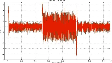
Firstly simulation with nominal parameters giv performed. Figures 5 to 9 show the simulation result
case when reference speed is increases from 250 rpm to 500 rpm and then decreases from 500 rpm to 250 rpm
[image:6.612.316.554.142.277.2]parameters.
Figure 6: Electromagnetic torque with nominal : Motor speed with nominal parameters
Firstly simulation with nominal parameters given in table 1 is show the simulation results for the reference speed is increases from 250 rpm to 500 rpm to 250 rpm with nominal
: Electromagnetic torque with nominal parameters
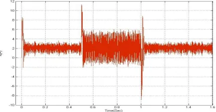
[image:6.612.17.248.356.486.2]Figure 8: idswith nominal parameters
Figure 9: iawith nominal parameters
In second case simulation is performed with parameter variation of 125% of some parameter of table
parameters are r =1.24 Ω, Ld= Lq = 7.28 mH, J=
TL=1.5 N-m. The PMSM parameters usually vary due to aging,
wear, and change of operating point. It can be verified that the proposed fuzzy controller gives very performance
transient response, a small steady state error and a good performance under model parameter and load torque variation.
with nominal parameters
with nominal parameters
[image:6.612.35.254.520.651.2] [image:6.612.299.517.560.668.2]Figure 10: Motor speed with parameter variation
[image:7.612.11.231.164.281.2].
Figure 11: Electromagnetic torque with parameters variation
[image:7.612.39.256.376.489.2]Figure 10 to 14 show the simulation result of the motor under parameter variation for same variation of speed as in case 1. Under these conditions also motor speed track the reference speed signal quit accurately.
[image:7.612.14.256.548.655.2]Figure 12 q-axis current with parameters variation
Figure 13: d-axis current with parameters variation
Figure 14: Motor phase current iawith parameters variation
CONCLUSION
Fuzzy model of PMSM is purposed and based on this fuzzy model T-S fuzzy speed regulator is given. In the last simulation for speed regulation was done using two rule T-S fuzzy model. Simulation is first time performed with nominal motor parameter and second time with 125% variation of some parameter. From the simulation results we conclude that the response of proposed fuzzy speed regulator is fast as compared to conventional speed controller. Effect of parameters variation on the performance of regulator is very low with fuzzy speed regulator. Performance is almost invariant with respect to parameters and load torque variations. Simulation results have been given to show the effectiveness of proposed design method.
REFERENCES
[1] Han Ho Choi , Nga Thi-Tuy Vu, and Jin-Woo Jung “Design and Implementation of a Takagi–Sugeno Fuzzy Speed Regulator
for a Permanent Magnet Synchronous Motor” IEEE
Transactions On Industrial Electronics, Vol. 59, No. 8, pp 3069-3077,August 2012
[2] A. V. Topalov, G. L. Cascella, V. Giordano, F. Cupertino,
and O. Kaynak,“Sliding mode neuro-adaptive control of electric
drives,” IEEE Trans. Ind. Electron., vol. 54, no. 1, pp. 671–679,
Feb. 2007.
inertia,” IEEE Trans. Ind. Electron., vol. 56, no. 8, pp. 3050– 3059, Aug. 2009
[4] H. Z. Jin and J. M. Lee, “An RMRAC current regulator for permanent magnet synchronous motor based on statistical model interpretation,” IEEE Trans. Ind. Electron., vol. 56, no. 1, pp. 169–177, Jan. 2009.
[5] MarianTarnık Jan Murga “Model reference adaptive control
of permanent magnet synchronous motor” Journal of
ELECTRICAL ENGINEERING, VOL. 62, NO. 3, 2011, 117–
125
[6] N. J. Patil, R. H. Chile and L. M. Waghmare “Fuzzy adaptive controllers for speed control of PMSM drive” International Journal of Computer Applications vol.1 –No. 11 2010, 0975 –8887
[7] Jin-Woo Jung*, Han Ho Choi*, and Dong-Myung Lee “Implementation of a robust fuzzy adaptive speed tracking control system for permanent magnet synchronous motors” Journal of Power Electronics, Vol. 12, No. 6, November 2012
[8] Han Ho Choi, Jin-Woo Jung “Takagi–Sugeno fuzzy speed controller design for a permanent magnet synchronous motor” Mechatronics 21 (2011) 1317–1328
[9]T. Takagi and M. Sugeno, “Fuzzy identification of systems and its applications to modeling and control,” IEEE Trans. Syst., Man, Cybern., vol. SMC-15, no. 1, pp. 116–132, Jan. 1985.
[10] Mukhtar Ahmad, High Performance AC Drives Modeling Analysis and Control Springer 2010.
[11] B. K. Bose, Modern power electronics and AC drives: Prentice Hall, 2002.
[12]R. Krishnan, Electric Motor Drives Modeling, Analysis, and Control Pearson Education, 2001.
[13]B. K. Bose, Power Electronics and Variable Frequency Drives, 1 ed: Wiley, John &
[14] Simulation of direct torque controlled permanent magnet synchronous motor drive , Selin Özçıra, Nur Bekiroğlu Engin, Ayçiçek,Yildiz Technical University, Department of Electrical Engineering, 34349 Besiktas, Istanbul, Turkey
[15]Enrique L. Carrillo Arroyo, “Modeling and Simulation of Permanent Magnet Synchronous Motor Drive System”, in ELECTRICAL ENGINEERING University Of Puerto Rico Mayagüez Campus 2006
[16] R.-J. Wai and K.H. Su, “Adaptive enhanced fuzzy sliding-mode controlfor electrical servo drive,” IEEE Trans. Ind. Electron., vol. 53, no. 2,pp. 569–580, Apr. 2006.
[17] T. A. Johansen, R. Shorten, and R. Murray-Smith, “On the interpretation and identification of dynamic Takagi–Sugeno
fuzzy models,” IEEE Trans. Fuzzy Syst., vol. 8, no. 3, pp. 297–