Technology (IJRASET)
Mathematical Modelling and Simulation of
Brushless DC Motor Using MATLAB
Vikramarajan Jambulingam
Electrical and Electronics Engineering, VIT University, India.
Abstract: Due to high efficiency, low maintenance and high torque the BLDC motor are used in many industrial and traction application. It is also an alternate motor for brushed DC motor and induction motor. In this paper the three phase brushless DC motor model is designed and test under trapezoidal back electromotive force using MATLAB software. On the other hand parameters like Back EMF, current, speed and torque are evaluated for the designed models of BLDC motor.
Keywords: Brushless DC motor, Trapezoidal back EMF, PMBLDC.
I. INTRODUCTION
The replacement for conventional DC motor is BLDC motor in many cases. The characteristic of DC motor is retained by BLDC motor except brushes and commutator. To provide large amount of torque for a wide range of speed BLDC motor suits the most with high performance. Actually for applications that require high power, high reliability and high efficiency BLDC motor is the ideal choice. A small BLDC motor is used in hard disk drives and large BLDC motor is used in electric vehicles. In BLDC motor physical commutator is not necessary because the electric current powers the permanent magnet that causes rotation in motor. So current commutation takes place because of solid state switches. In this case commutation happens electronically. Most commonly used BLDC motors are three phases rather than two phase BLDC motor.
Due to the rotor rotation voltage is induced in the stator winding called back-EMF of BLDC motor. So torque is primarily influenced by back-EMF of BLDC motor. In case size of the motor and torque delivered ratio is higher so the critical factors are space and weights in certain application to make it useful. When practical speaking the torque ripple exit mainly due to imperfection emf, ripple current and phase current commutation. Due to the magnet size and shape of the BLDC motor the imperfection emf is occurred. On the other side hysteresis and PWM control generates ripple in current. The Bimbra [1] has explained the generalized machine theory.
II. CONSTRUCTION AND OPERATING PRINCIPLE OF BLDC MOTOR
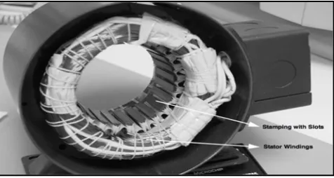
[image:2.612.188.426.532.659.2]To put up even number of winding along the inner periphery the stator of brushless DC motor comprises axially slotted and steel lamination [Figure.1]. The windings are distributed in a different way but other than this the brushless DC resembles the induction motor.
Figure 1: slotted steel ring with axial windings of a BLDC motor
Technology (IJRASET)
modern-day units tend to use rare earth magnets. These magnets generates greater flux density and also very high in cost. Therefore comparatively the brushless DC motor delivers high power than brushed DC motor due to the usage of powerful magnets.
One after another the BLDC motor’s electronic commutator energizes the stator coils and generates a rotating electric field that ‘drags’ the rotor around with it. N “electrical rotations” equates to one mechanical rotation, where N is the number of magnet pairs. To indicate the relative position of stator and rotor to the controller three phase effect sensors are embedded in the stator of the three phase brushless DC motor. The hall sensor helps brushless DC motor to energize the winding in a correct sequence and at the correct time.Constructionally the all sensor is mounted on the non driving side of the system [Figure.2].
Figure 2: Hall sensors are embedded in the stator of a BLDC motor
The high or low signal is generated during the rotor magnetic poles passes the hall sensors by combining the signals from the three sensors. Due to the movement of the winding through the associated magnetic field the potential voltage is generated by the electrical motors and it can be called as electromotive force. As per Lenz’s law the magnetic field which opposes original change in flux will give rise in winding current. In general this means electromotive force tends to resist the rotation of the motor and referred as back electromotive force. The Baldursson [2] has developed brushless DC motor modelling and control. Padmaraja [3] has developed the fundamentals of brushless DC motor.
Advantages of brushless DC motor over brushed Dc motor:
Higher efficiency and speed operation Quick acceleration and responsive
High Power Density and long operating life High Reliability and dynamic response
Speed versus torque characteristics are better
III. MATHEMATICAL MODELLING OF THE BLDC MOTOR
.(1)
a b c
a a a a ab ac a t t
di
di
di
V
i R
L
M
M
e
Eq
d
d
dt
.(2)
b a c
b b b b ba bc b t t
di
di
di
V
i R
L
M
M
e
Eq
d
d
dt
.(3)
c b a
c c c c cb ca c t t
di
di
di
V
i R
L
M
M
e
Eq
d
d
dt
Where,
R R R
a,
b,
c-Stator resistance of phase a, b and c.,
,
a b c
L L L
- Stator inductance of phase a, b and c., ,
a b c
i i i
-Stator current of phase a, b and c.,
,
a b c
Technology (IJRASET)
a b c
R
R
R
R
-Mutual inductance between phases,
,
a b c
L L L
-Stator self inductance of phase a, b and c.In this case,
L
a
L
b
L
c
L
ab ac bc ba ca cb
M
M
M
M
M
M
M
Assuming three phase balanced system, all phase resistance are equal.
a b c
R
R
R
R
Let us rearrange the above equations 1, 2 and 3. We get,
.(4)
a b c
a a a
t t
di
di
di
V
i R
L
M
M
e
Eq
d
d
dt
.(5)
b a c
b b b
t t
di
di
di
V
i R
L
M
M
e
Eq
d
d
dt
.(6)
c b a
c c c
t t
di
di
di
V
i R
L
M
M
e
Eq
d
d
dt
Let us neglect mutual inductance in equations 4, 5 and 6. We get,
.(7)
a a a a
t
di
V
i R
L
e
Eq
d
.(8)
b b b b
t
di
V
i R
L
e
Eq
d
.(9)
c c c c
t
di
V
i R
L
e
Eq
d
IV. TRAPEZOIDAL BACK EMF
According to Lenz’s law each winding of the brushless DC motor generates back emf which opposes main voltage supplied to the winding. The polarity of this back emf is in opposite direction of the energized voltage. Back electromotive force depends on three factors mainly. They are as follows,
The angular velocity of rotor.
Magnetic field generated by rotor magnets. Number of turns in the stator winding.
The number of turns in the stator winding and rotor magnetic field will remain constant after a motor is designed. If speed increases back emf is also increases because the factor that governs back emf is angular velocity or speed of the rotor. By subtracting the back emf value from supply voltage the potential difference across the winding can be determined. So considering the back emf as a constant the motor is designed. The motor is running at rated speed to deliver rated torque and current. The potential difference between supply voltage and back emf will be sufficient.
In case motor is running beyond the rated speed. Back emf may increases. So potential difference is decreased across the winding and also reduces. Actually current drawn makes in drooping torque curve. A new simulation model is developed by Jeon [4]. For complete MATLAB modelling Simulink user’s guide is helpful [5]. In general PMAC motor is classified in to two types. They are as follows:
Technology (IJRASET)
Brushless DC motor
The PMSM produces sinusoidal back emf and to be supplied with sinusoidal current and voltage. In case of BLDC motor it produces trapezoidal back emf and to be supplied with quasi-rectangular shaped currents. The back emf is generated in each winding of the BLDC motor during rotor rotation and opposes supplied voltage in the main windings. Hence the polarity of the back electromotive force is opposite to energized voltage. The phase winding of stator is displaced by 120 degree each. The windings are distributed such a way that it produces trapezoidal back electromotive force. By energizing the phase pairs the PMBLDC motor produces constant torque. In order to produce constant torque the trapezoidal back emf is synchronised with quasi square waveform by controlling the three phase currents. The instantaneous back emf in brushless DC is written as,
( ) *
*
.(10)
a a a
E
f
K
Eq
( )*
*
.(11)
b b b
E
f
K
Eq
( ) *
*
.(12)
c c c
E
f
K
Eq
-Mechanical speed of rotor
-Electrical position of rotorBy assuming the identical back emf for all three phases modelling of back electromotive force is done. The numerical expression of the back emf is obtained based on rotor position. So the symmetric three phase back electromotive force waveforms are generated at every operating speed with rotor position and speed command. The back electromotive force in the windings are represented as follows, 6 0 6 5 6 6
6 5 7
6 .(13) 6 6 7 11 6 6 6 11 12 2 6 a E E E
e E Eq
E E E
0
6
6
5
4
2
6
5
9
.(14)
6
6
6
9
11
10
6
6
11
2
6
bE
E
E
e
E
Eq
Technology (IJRASET)
0
2
6
2
6
2
7
.(15)
2
6
6
7
9
8
6
6
9
2
6
cE
E
E
e
E
Eq
E
E
E
The back electromotive force is the function of rotor position and represented as
f
a( ),
f
b( ),
f
c( )
with limit values between -1 & 1.By substituting E=1 in equations 13, 14 and 15. We get,
6
0
6
5
1
6
6
6
5
7
( )
6
.(16)
6
6
7
11
1
6
6
6
11
12
2
6
af
Eq
1
0
6
6
5
4
2
6
5
9
( )
1
.(17)
6
6
6
9
11
Technology (IJRASET)
1
0
2
6
2
6
2
7
( )
1
.(18)
2
6
6
7
9
8
6
6
9
1
2
6
cf
Eq
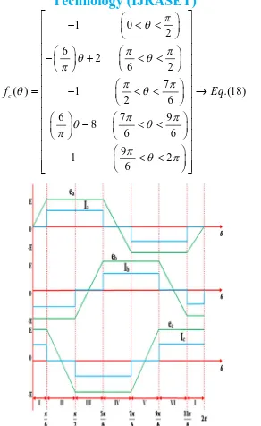
[image:7.612.167.459.67.543.2]
Figure 3:Back electromotive force and phase current waveform of brushless DC motor
V. TORQUE GENERATION
Theoretical motor constant ‘Kt’ is the product of torque and supply current ‘I’.
a b c
T
T
T
( ) ( ) ( ) ( ) t motor t a t b t c
K
K
K
K
motor a b c
i
i
i
i
-Angle,
,
a b c
Technology (IJRASET)
*
2
d
P
dt
The generated electromagnetic torque is given by,
[
a a b b c c]
e
e i
e i
e i
T
in N-M{
( )
( )
( )
e t a a b b c c
T
K
f
i
f
i
f
i
1
e
d
J
B
T
T
dt
The relation between angular velocity and angular position is given by,
*
2
d
P
dt
1T
-load torque
-Motor inertia B-Damping Constant P-Number of polesVI. SIMULATION MODEL OF THE BLDC MOTOR TABEL I
Voltage (Vdc) 80 volts
Damping constant (Tload) 0.35 N-M
Resistance (R) 4.98 ohms Inductance (L) 2.05 mH Moment of inertia (J) 15.17 106 Kgm2
Number of poles 4
[image:8.612.77.512.478.700.2]Table.1. Specification of BLDC motor
Technology (IJRASET)
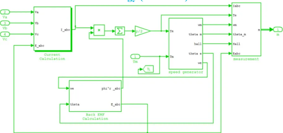
[image:9.612.73.544.318.472.2]Figure 5: MATLAB Simulink Sub system model of BLDC motor
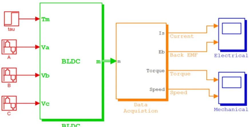
Figure 6: MATLAB Simulink data acquisition model of BLDC motor
VII. SIMULATION RESULTS
[image:9.612.130.472.535.697.2]Technology (IJRASET)
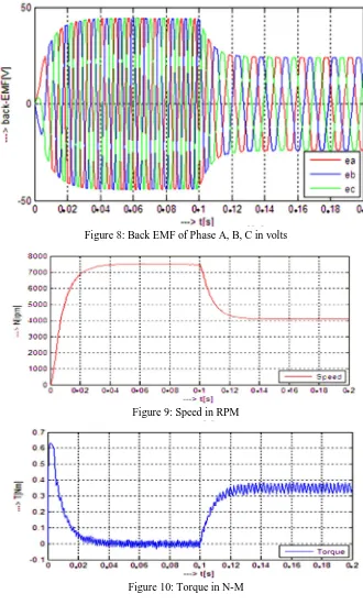
Figure 8: Back EMF of Phase A, B, C in volts
Figure 9: Speed in RPM
Figure 10: Torque in N-M
VIII. CONCLUSION
Technology (IJRASET)
REFERENCES
[1]P. S. Bimbhra, “Generalized Theory of Electrical Machines”, Khanna Publishers, Delhi, India, 2001, pp. 93-98. [2]Padmaraja Yedamale, “Brushless DC (BLDC) Motor Fundamentals”, Microchip Technology Inc. 2003.
[3]S. Baldursson, “BLDC Motor Modelling and Control – A MATLAB/Simulink Implementation”, Master Thesis, May, 2005.
[4]Y.S. Jeon, H.S.Mok, G.H.Choe, D.K.Kim and J.S. Ryu, “A New Simulation Model of BLDC Motor with Real Back EMF waveforms”, IEEE CNF. On computers in Power Electronics, 2000. COMPEL 2000.pp. 217- 220, July 2000.
[5]Sim power Systems for use with Simulink, user’s guide, Math Works Inc., Natick, MA, 2002. Math Works, 2001, Introduction to MATLAB, the Math Works, Inc.
BIOGRAPHY