GE-International Journal of Engineering Research
Vol. 4, Issue 3, March 2016 IF- 4.721 ISSN: (2321-1717)
© Associated Asia Research Foundation (AARF) PublicationWebsite: www.aarf.asiaEmail : [email protected] , [email protected]
DESIGN AND DEVELOPMENT OF A TIME EFFICIENT IMAGE DENOISING
ALGORITHM FOR REAL TIME SYSTEMS
K.Sivakumar
1, C.Sunitha Ram
2, D.Gayathri
3 *1Department of Computer Science and Engineering, SCSVMV University,India *2
A Department of Computer Science and Engineering, SCSVMV University,India *3
A Department of Computer Science and Engineering, SCSVMV University,India
ABSTRACT
Transmission of multimedia data over the network channels is unavoidable now a day in all the modern communication systems. The data transfer may be in real-time and non real-time based on the application requirements. In some applications images plays important part. Raw images captured using various devices contains noise. These must be free from noise before and after the transmission, if the image having noise it should be pre-processed (de-noise) before it going to use. The demand for images, video sequences and computer animations has increased drastically over the years for multimedia in an Image Data Acquisition System. For an efficient design of DAS, there is need for a pre-processing of the images for the removal of noise. The main aim of this paper titled “design and development of a time efficient image de-noising algorithm for real time systems using Java” is to design an algorithm that is very simple in implementation, fast in encoding time and hence can be used in the real-time Data Acquisition System processed with high efficient time and space in order to ensure that no incoming data is missed out and to prove that the image quality (PSNR) is better and time consumption is lesser. In this paper we proposed A Modified Decision Based Unsymmetrical Trimmed Mean and Median filter (MDBUTMMF) algorithm for the restoration of gray scale, and color video frames that are highly corrupted by salt and pepper noise.
Keywords—Salt and Pepper noise, Color Noise, Shear Sort, Un-symmetric Trimmed Mean and Median Filter, Run Time.
1. INTRODUCTION
Introduction to Image Noise and Denoise: Image noise is random variation of brightness or color information in images, and is usually an aspect of electronic noise. It can be produced by sensor and circuitry of a scanner or digital camera. The image noise can be also originated in film grain and in the unavoidable
short of noise of an ideal photon detector. It is an undesirable by-product of image that adds spurious and extra information. Image de-noising is process of removal of noise in the images or video.
The magnitude of image noise can range from almost imperceptible specks on a digital photograph taken in good light, to optical and radio astronomical images which are almost entirely noise, from which a small amount of information can be viewed derived by sophisticated processing. One of the fundamental challenges in the field of image processing and computer vision is image denoising, where underlying goal is to produce an estimate of the original images by suppressing noise from a contaminated version of image. Image noise could be caused by sensor and environment condition which are often not possible to avoid. Therefore image denoising plays an important role in wide range of applications, where the obtaining original image content is crucial, while many algorithms have been proposed for the purpose of image denoising. Among various types of noise, here we need to concentrate on the pepper and salt noise and color noise which are present in the images. Ultimate goal of this project is “to design an image denoising algorithm for removal of both color and pepper and salt noise, that is very simple in implementation, fast in encoding time and hence can be used in the real-time Data Acquisition System processed with high efficient time and space in order to ensure that no incoming data is missed out thereby ensuring that the image quality (PSNR) is better and time consumption is lesser.
1.1 Problem Statements
for researchers because noise removal introduces artefacts and causes blurring of the images. Noise modelling in images is greatly affected by capturing instruments, data transmission media, image quantization and discrete sources of radiation. Different algorithms are used depending on the noise model. Most of the natural images are assumed to have additive random noise which is modelled as a Gaussian. Speckle noise is observed in ultrasound images. De noising is carried out only in order to improve the performance of the image including Peak Signal to Noise Ratio(PSNR), Image Enhancement factor(IEF) but for real time application image processing must be done efficiently and in lesser time.
Currently existing techniques like Standard Median Filter (SMF) and Decision Based Algorithm (DBA) are widely used in image de-noising and they achieve good PSNR values. Alternative methods are explored to achieve image de-noising with lesser computational complexity; Decision Based Un symmetric Trimmed Median Filter is one such method. Even though there are many algorithms, it is necessary for us to find algorithms that are simple in implementation, time efficient and at the same time generate good image quality. The main aim of this proposed algorithm is to design an algorithm that is very simple in implementation, faster in encoding time and hence can be used in the real-time Data Acquisition System processed with high efficiently in order to ensure that no incoming data is images are to be missed out thereby necessitating contrasting goal of high PSNR and low time consumption.
1.2 Method Used
In this proposed algorithm I used Modified Decision Based Unsymmetrical Trimmed Mean and Median filter (MDBUTMMF) algorithm for the restoration of gray scale, and color image that are highly corrupted by salt and pepper noise. In this method used both mean and median pixels to be processed. But other method used only median is taken for removal of noise. This method also used shear shorting for implementing denoise algorithm. This sorting method consumes less comparison compared to other sorting methods. Below shows the various sorting methods and number comparison required is listed. Even if the other two methods like merge and heap sort consume less comparison I taken shear sort because of which are suitable for sorting matrix elements. This shear sorting methods the elements which are in the matrix are arranged in ascending order how like a snake are moving.
SORTING TECHNIQUES
Number of Comparisons required to sort the entire 3x3 window (worst case) Bubble sorting o(n2) 81
Insertion sorting o(n2) 81 Selection sort o(n2) 81
Merge Sort o(n log n) 25 Heap Sort o(n log n) 28 Quick Sort o(n2) 81 Shear sorting
o(sqrt(n)(2n))
54
Snake like Modified shear sorting (proposed Algorithm)
o(4n+2sqrt(n))
42
Table.1. Complexities of various sorting algorithm
1.3 Existing De-noising Techniques
Currently existing techniques like Standard Median Filter (SMF) and Decision based algorithm are widely used in image de noising and they achieve good PSNR values. There are other methods to achieve image de noising with lesser computational complexity. Decision Based Un symmetric Trimmed Median filter (DBUTMF) and MDBUTMF are such methods. In this project, it is proposed to use Modified Decision Based un Symmetric Trimmed Mean Median Filter [MDBUTMMF] method to achieve de noising with lesser computational time.
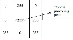
In decision based algorithm window size of 3x3 is used. The detection of noise and noise free pixels is decided by checking if the value of processed pixel element lies between the minimum (0) and maximum (255) values that occurs inside the selected window. If the processing pixel value is 0 or 255 it is processed otherwise it is left unchanged. In addition, the DBA uses simple fixed length window of size 3x3, and hence it requires lower processing time while compared to SMF. But, at high noise density levels the median value may also be noisy. In this case, neighbouring pixel is used for replacement.
This repeated replacement of neighbouring pixels produces striking effect. Hence, details and edges are not recovered satisfactorily, especially when the noise level is high. At high noise densities, if the selected window contains all 0‟s or 255‟s or both then, trimmed median value cannot be obtained. So, this algorithm does not give better results at very high noise densities i.e. at >60%. Hence it is proposed to use Modified Decision Based Un-symmetric Trimmed Median Filter (MDBUTMMF) algorithm to overcome the problems with MDBUTMF Algorithm.
1.4 Disadvantages of MDBUTMF
At high noise densities DBUTMF often exhibits blurring of large window sizes and insufficient noise suppression for small size.
Information losses occur in most of the median filters because it operates uniformly across all the frames and it modifies both noise and noiseless.
In this algorithm neighbouring pixels is used for replacement. The repeated replacement of the neighbouring pixels produces striking effect; hence the details and edges are not recovered satisfactorily.
It does not give better result at very high noise densities i.e. greater than 50%, so it is proposed to go for Modified Decision Based Un-Symmetric Trimmed Mean and Median Filter (MDBUTMMF) algorithm.
2. PROPOSED METHOD
2.1 Procedure
Proposed Algorithm (Modified Decision Based Un-symmetric Trimmed Mean and Median Filter [MDBUTMMF]). In this proposed method there are few important steps are being used.
1. It uses simple fixed length window of size 3x3 and hence it require lower processing time
2. Concept of sorting algorithm used in this project (shear sharing).
3. Selecting the mean and median values from the 3x3 window for replacing corrupted pixels.
4. Apply the above three step for removing the color noise from the image by checking color noise ranges from greater than 0 and less than 254.
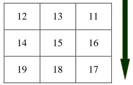
2.2 Select 3x3 window size
This is the first step which is used in the proposed method. The 3x3 windows can be selected from the pixels being processed as follows.
o Select the row, column value from the current pixels being processed.
o Decrement row and column value by one to get stat x and stat y value.
o Increment the row and column value by one to get end x and end y value.
o After calculating startx, starty , endx and endy values then go for next step apply the sorting .
Fig.1. 3x3 size window from image
2.3 Shear sorting method
Sorting is the most important operation used to find the median and mean of a window. There are different sorting algorithms such as binary sort, bubble sort, merge sort, quick sort etc. All the existing sorting algorithms require more comparators. In this project a new snake like improved shear sorting algorithm is proposed for ordering the entire array of processed pixels table1 shows the various sorting methods and its Complexities sorting algorithm.
Shear sorting algorithm steps:
1. A 2-D window of size 3x3 is selected. The pixel to be processed is þ(x,y).
13 17 12 18 11 19 15 14 16
Fig. 2. Matrix before Sorting (Original)
2. The pixel value inside the window are sorted, And þmin, þmax and þmed determined as following steps
[image:3.612.345.479.518.604.2]1) The rows of the window are arranged in ascending order. 2) The columns of the window are arranged in ascending order. 3) The right diagonal of the window is now arranged in ascending order.
Fig.3.Rows of the window are arranged in ascending order is shown in step3.
Fig.4. Columns of the window are arranged in ascending order is shown in step 2.
12 13 17 19 18 11 14 15 16
12 13 11
14 15 16
Fig.5. Right diagonal of the window is now arranged in ascending order is shown in step 3.
3. Case i: The þ(x,y) is an uncorrupted pixel if þmin < þ(x,y) < þmax , þmin > 0 and þmax < 255, the pixel being processed is left unchanged. Otherwise þ(x,y) is a corrupted pixel.
Case ii: If þ(x,y) is a corrupted pixel, it is replaced by its median value if þmin<þmed<þmax and 0< þmed <255.
Case iii: If þmin<þmed<þmax is not satisfied or 255< þmed=0, then þmed is noisy pixel. In this case, the þ(x,y) is replaced by the value of neighbourhood pixel value.
4. Above steps are repeated until the process is completed for the entire images.
2.4 Select the Mean and Median value from the sorted windows
[image:4.612.25.222.417.642.2]Let us take the pixels set as (……..2,5,9,19,24,54,5,87,9,10,44,32,21,13,24, 18, 26, 16, 19, 25, 39,47,56,71,91,61,44,28………) on the window you have selected. Below diagram shows how the median can be calculated using shear sorting
Fig. 6. It shows median calculation using Shear sorting
2.5 Modified Decision Based Un-Symmetric Trimmed Mean And Median Mediam Filter (MDBUTMMF):
The proposed Modified Decision Based Un-symmetric Trimmed Median Filter (MDBUTMF) algorithm processes the corrupted video frame by first detecting the impulse noise. The processing pixel is checked whether it is noisy or noise-free. That is, if the processing pixel lies between maximum and minimum gray level values then it is noise free pixel, it is left unchanged. Each and every pixel of the frame is checked for the presence of salt and pepper noise. Different cases are illustrated in this section.
If the processing pixel is noisy and all other pixel values are either 0‟s or 255‟s is illustrated in case (i).
If the processing pixel is noisy pixel that is 0 or 255 is illustrated in case (ii).
If the processing pixel is not noisy and its value lies between 0 and 255 is illustrated in case (iii).
Case (i): If the selected window contains salt and pepper noise as processing pixel and neighbouring pixel values contains all pixels that adds salt and pepper noise to the video frame.
Fig. 7. Processing pixel with error
Since all the elements surrounding þ(x,y) are 0‟s and 255‟s. If one takes the median value it will be either 0 or 255 which is again noisy. To solve this problem, the mean of the selected window is found and the processing pixel is replaced by the mean value. Here the mean value is 170. Replace the processing pixel by 170.
Case (ii): If the selected window contains salt and pepper noise as processing pixel and neighboring pixel values contains some pixels that adds salt and pepper noise to the image frame.
11 12 13
16 15 14
[image:4.612.397.525.447.517.2]Fig. 8. „0‟ processing pixel.
[image:5.612.96.188.243.309.2]“0” is the processing pixel. Salt and pepper noise is now eliminated from the selected window. That is elimination of 0‟s and 255‟s. The 1-D array of the above matrix is [78 90 0 120 0 255 97 255 73]. After elimination of 0‟s and 255‟s the pixel values in the selected window will be [0, 0, 73, 78, 90, 97, 120, 255, and 255]. Here the median value is 90. Hence replace the processing pixel þ(x,y) by 90.
Fig. 9. Median pixel selection
[image:5.612.61.212.365.432.2]Let us consider if the median is also a corrupted pixel means we go for to find out the mean values as follows.
Fig. 10. Median pixel value selection
The 1-D array of the above matrix is [0, 0, 73, 97, 255, 255, 255, 255, and 255].
Mean value= (73+97) /2 =85 Hence replace the processing pixel þ(x,y) by 85.
Case (iii): If the selected window contains a noise free pixel as a processing pixel, it does not require further processing. For example, if the processing pixel is 90 then it is noise free pixel.
Fig. 11. Noise free pixel
Where „90‟ is the processing pixel. Since 90 is a noise free pixel it does not require further processing.
2.6.Advantages of MDBUTMMF algorithm
Blurring of image can be reduced.
The original frame will be preserved, when the noise level is over 40%.
Information losses occur can be reduced.
Repeated replacement of the neighboring pixels produces striking effect can be eliminated; hence the details and edges are recovered satisfactorily.
Running time is very less compared with other algorithms.
2.7 Calculate the Image quality Measurements
This module can be used performs the calculation of various image quality measurements like PSNR-Peak Signal to Noise Ratio, Mean Square Error, Noise Percentage, Image Enhancement factor and running time of the operations. After the calculation it will display the various image quality factors on the appropriate place. The following are the image quality measurements
Peak Signal to Noise Ratio[PSNR]
Mean Square Error[MSE]
2.7.1 Peak Signal to Noise Ratio [PSNR] and MSE
The phrase peak signal-to-noise ratio, often abbreviated PSNR, is an engineering term for the ratio between the maximum possible power of a signal and the power of corrupting noise that affects the fidelity of its representation. Because many signals have a very wide dynamic range, PSNR is usually expressed in terms of the logarithmic decibel scale.
The PSNR is most commonly used as a measure of quality of reconstruction of lossy compression codecs (e.g., for image compression). The signal in this case is the original data, and the noise is the error introduced by compression. When comparing compression codecs it is used as an approximation to human perception of reconstruction quality, therefore in some cases one reconstruction may appear to be closer to the original than another, even though it has a lower PSNR (a higher PSNR would normally indicate that the reconstruction is of higher quality). Given a reference image f and a test image g, both of size M×N, the PSNR between f and g is defined by:
The PSNR value approaches infinity as the MSE approaches zero; this shows that a higher PSNR value provides a higher image quality. At the other end of the scale, a small value of the PSNR implies high numerical differences between images. For color images the image is converted to a different color space and PSNR is reported against each channel of that color space, e.g RGB.
[image:5.612.63.228.543.628.2]Acceptable values for wireless transmission quality loss are considered to be about 20 dB to 25 dB. When the two images are identical, the MSE will be zero. For this value the PSNR is undefined or infinity.
3. PERFORMANCE ANALYSIS
The following tables shows the performance of the proposed algorithm for the various image quality measurements like PSNR, MSE, Running Time and Noise Percentage.
Noise
% PSNR MSE
Run Time In
milliseconds In seconds 10 36.99 13 77 0.077 20 32.95 33 87 0.087 30 31.9 42 74 0.074 40 30.07 64 79 0.079 50 28.84 85 84 0.084 60 28.31 96 94 0.094 70 27.09 127 90 0.09 80 26.83 135 98 0.098 90 25.01 169 95 0.095
Table 2: Performance of proposed algorithms at different noise densities for PSNR, MSE, Run time and Noise percentage LENA Image
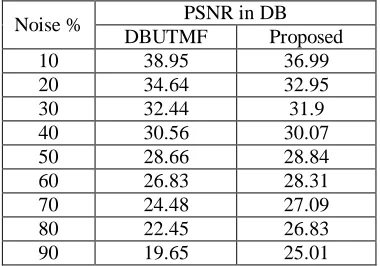
Noise % PSNR in DB DBUTMF Proposed 10 38.95 36.99 20 34.64 32.95 30 32.44 31.9 40 30.56 30.07 50 28.66 28.84 60 26.83 28.31 70 24.48 27.09 80 22.45 26.83 90 19.65 25.01
Table 3: Performance analysis of proposed and DBUTMF Algorithms at different noise densities for PSNR, MSE, Run time and Noise percentage for LENA image
From the above table we can understand that the image qualities are increased when the noise level is greater than the 50%. Not only but also the proposed algorithms takes lesser time compared to other algorithms.
Error/ Methods
PSMF DBA DBUT MF
MDBUTM F
Proposed
10 % 32.42 38.24 38.95 39.93 36.99 20 % 30.39 34.69 34.64 36.98 32.95 30 % 27.56 32.16 32.44 33.66 31.9 40 % 24.59 30.59 30.56 32.42 30.07 50 % 21.23 28.54 28.66 30.25 28.84 60 % 14.22 26.93 26.83 28.43 28.31 70 % 11.84 24.64 24.48 26.30 27.09 80 % 10.02 22.32 22.45 23.14 26.83 90 % 8.57 19.15 19.65 20.50 25.01
Table 4: Performance analysis of proposed and various existing method for PSNR Value
3.1 Performance comparison chart
[image:6.612.54.262.203.349.2] [image:6.612.330.597.388.587.2] [image:6.612.61.251.400.533.2]Fig.12. Comparison between various denoising methods
Fig.13. Noise percentage between various denoising methods
The below charts clearly stated that the proposed method run faster than the other methods.
Fig.14. Error vs runtime between various denoising methods
3.2 Execution layout for proposed method and performance analysis
4. CONCLUSION AND FUTURE
ENHANCEMENTS
4.1 CONCLUSION
In this project, a new algorithm (MDBUTMF) is proposed, developed and tested which gives better performance in compare with DBUTMF and other existing noise removal algorithms in terms of PSNR, MSE, noise density and running time.
The performance of the algorithm has been tested at low, medium and high noise densities on both gray-scale and color images. Even at high noise density levels the MDBUTMF gives better results in comparison with other existing algorithms. Both visual and quantitative results are demonstrated. The proposed algorithm is effective for salt and pepper noise and color noise removal in images at high noise densities.
4.2 FUTURE ENHANCEMENTS
Image denoising playing important role in the pattern recognition, image processing, machine learning and videos etc, so is necessary for us to design a high speed data acquisition system is important one. Using this project we can extend for removing the noise from various applications like multimedia, video traffic monitoring and film edition etc… particularly video de noising is one of them.
We can implement the software for removing noise from the highly corrupted by both color and pepper and salt noise in the images or videos.
REFERENCES
[1]. C.K Li and H. Yuen “High performance Image compression Technique for Multimedia Applications” IEEE transaction on Consumer electronics Vol 42 no 2 May 1996.
[2]. A Decision Based Unsymmetrical Trimmed Variants for the Removal of High Density Salt and Pepper Noise By K.Vasanth, V.Jawahar senthilkumar Rajesh.V,. International Journal of Computer Applications (0975 – 8887) Volume 42– No.15, March 2012.
[3]. Rafael C. Gonzalez and Richard E Woods “ Digital Image processing “ Third Edition PHI ltd 2008.
[4]. Performance Analysis of Various Impulse Noise Reduction Techniques in Images., By Shiv Singh, Dr. G.C.Lall, International Journal of Advanced Research in Computer Science and Software Engineering., Volume 2, Issue 6, June 2012 ISSN: 2277 128X
[6]. K. Iswarya , V jayaraj and D benezer “ A new and efficient algorithm for the removel of high density salt and pepper noise in images and Videos” in second conf, compurer modelling and simulation 2010
[7]. Z. dengwen C Wengang “ Image denoising with an optimal threshold and neighbouring window “ Pattern recognition letter 2008
[8]. GY chen T D Bui and A krzyzak “Image denoising using Neighbouring wavelet coefficients Icassp.
[9]. Restoration of High Density Salt and Pepper Noisy Gray & Color Videos using MDBUTMF., By P. Rajesh*1, E. Kiran Kumar*2, B. Sony Rama*3, PVV Kishore#4 International Journal of Emerging Technology and Advanced Engineering Website: www.ijetae.com (ISSN 2250-2459, Volume 2, Issue 9, September 2012). [10]. Image quality metrics: PSNR vs. SSIM, Alain
Horé, Djemel Ziou, 2010 International Conference on Pattern Recognition.