Improving Power Transfer Capability
and Oscillation Damping of
Parallel Transmission Lines by using
Interline Unified Power Flow Controller
J. Naveen1, B.Viswanath2
PG Student [P&ID], Dept. of EEE, Vignan’s Institute of Information Technology, Visakhapatnam,
Andhra Pradesh, India1
Associate Professor, Dept. of EEE, Vignan’s Institute of Information Technology, Visakhapatnam,
Andhra Pradesh, India2
ABSTRACT: In modern power systems, power demand is continuously increasing. To meet the increased power demand, the power flow on the transmission lines are to be effectively controlled. For such purpose, power flow controllable devices are required. Unified Power Flow Controller (UPFC) is a FACTS device which controls the power
flow on the single transmission line and Interline Power Flow Controller (IPFC) controls the power flow in the parallel transmission lines or on the multi-lines. The Interline Unified Power Flow Controller (IUPFC) is the newest device, whichis the modified version of IPFC and UPFC.
In this paper, the Interline Unified Power Flow Controller (IUPFC) using two Voltage Source Converters(VSC) to provide the quality power supply, power transfer capability and oscillation damping. It uses two 48-Pulse voltage source converters.The two 48-Pulse voltage source converters are built with four three-level voltage source converters to produce 48- Pulse wave form which is nearer to the sinusoidal wave form. The 47th harmonic will be the lowest harmonic present in the output voltage .Shunt and Series converters are sharing a common DC capacitor. IUPFC consists of STATCOM and SSSC. It improves the powerflow on one transmission line in a power system and it
regulates bus voltage in another transmission line.
The (IUPFC) model is simulated using MATLAB Simulink on a practical bus system and the performances of the IUPFC in improving power transfer capability and oscillation damping are analysed on the parallel transmission lines. Simulation studies are also carried out on the behaviour of Interline Unified Power Flow Controller (IUPFC) under three-phase fault conditions. Simulation results show that with Interline Unified Power Flow Controller(IUPFC) in the system, there is an improvement in powerflow capability and oscillation damping.
KEYWORDS:Flexible AC Transmission System (FACTS), 48- Pulse Voltage Source Converter (VSC), Interline Unified Power Flow Controller (IUPFC), Static Synchronous Compensator (STATCOM), Static Synchronous Series Compensator (SSSC).
I.INTRODUCTION
and IPFC which has the capability of independently controls the active and reactive power flow on the parallel
transmission lines or multi transmission lines.
The basic concept of FACTS controllers isexplained in detail in the book, 'Understanding FACTS Concepts and Technology of Flexible AC Transmission Systems' by author N. Hingorani and L. Gyugyi [1]. The detailed explanation about series connected FACTS controller such as Static Synchronous Series Compensator (SSSC) and Interline Power Flow Controller given in [2,3]. Both SSSC and IPFC have the capable of operating in capacitive/ inductive mode of operation. SSSC provide the reactive power compensation to the individual line where it is connected and also it has the capable of transmitting the real power from underutilized line to the overloaded line these concepts was explained in [4].The paper [5] is a simple mathematical model of IPFC was proposed for the optimal control of power flow on the transmission lines. Mathematical models of generalized unified power flow
controller (GUPFC) and IPFC and their implementation in Newton power flow are demonstrate in [6].In the year 2002
a basic characteristic of Voltage Source Converter based Interline Power Flow Controller was discussed in paper [7] by the author Jianhong Chen T.T.Lei. Along with two basic control scheme, namely (i) Special Control Scheme and (ii) General control Scheme. The Special control scheme is designed for the power flow control of a transmission
system with two identical parallel lines while the general control scheme can be used to solve the power flow control
problem in a multi-line transmission system. Both special and general control schemes are based on the decoupled PI controller. A current source converter topology based inter line power flow controller was proposed in paper [8] along
with decoupled stat-feedback control for the injected voltage with a separated dc current controller. The dynamic model[9] of the system is derived and divided into a liner part and a nonlinear part. The linear part is controlled in an inner loop by a decoupled state-feedback controller. The nonlinear part is controlled in an outer loop by a PI controller which regulates the dc side current.
In this paper [10] the author proposed the 48-Pulse voltagesource converter for the Interline Unified Power Flow Controller. The proposed converter will have the capability of controlling the power flow and oscillation damping [11] on the parallel transmission lines and detailed switching level simulation model of IUPFC was developed on the MATLAB Simulink environment. The IUPFC developed model in this section is based on the d-q orthogonal co-ordinates[12].The IUPFC was developed to regulate the system voltage by compensating the reactive power.
II. PROBLEM FORMULATION
The demand on the power system increases gradually. The increasing in demand is fulfilled either by increasing the generation or by improving the existing system. FACTS technology is essential to alleviate some of the problem but not all of these di iculties. Converter based FACTS controller have the capability to control both active and reactive
power flow on the transmission line. The objective of the FACTS controller is to increase the power transfer capability of the transmission line. Active and Reactive power flow on a transmission line is given by.
P = (E1E2sin
(δ
))/X
Q = (E
1– E
2cos(δ
))/X
E1, E2 -Magnitude of voltage at the sending end and receiving end of the lines
X -Transmission line reactance
δ - Phase angle between sending end voltage (E1) & receiving end voltage (E2)
From the above equations, we can observe that real power flow on the transmission line has been increased by
compensating the reactive power on the transmission line by using the FACTS controller. The transfer capability of the transmission line can be increased or decreased by adjusting the any one of the following parameter E1, E2, X and.
III.PRINCIPLE OF OPERATION OF IUPFC
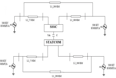
A 500 KV transmission line is controlled by the Interline Unified Power Flow Controller (IUPFC). The UPFC is located at the left end of the 75-km line L2, between the 500 kV buses B2 and B3, is used to control the active and
reactive powers flowing through bus B3 while controlling voltage at bus B6. It consists of two 100- MVA, three-level,
48-Pulse GTO-based converters, one connected in shunt at bus B6 and another connected in series between buses B2
and B3. The shunt and series converters can exchange power through a DC bus. The series converter can inject a
maximum of 10% of nominal line-to-ground voltage (28.87 kV) in series with bus B3. Controlling of the series
branch is different from the SSSC. In SSSC, the two degrees of freedom of the series converter are used to control the active and the reactive power.
This IUPFC converter can be operated in three modes: InterlineUnified Power Flow Controller (UPFC) mode: In this mode, the shunt and series converters are sharing a common DC bus. When the switches are open between the DC buses of the shunt and series converter, two additional modes are available: Shunt converter operating as a Static Synchronous Compensator (STATCOM) controlling voltage at bus B6, Series converter operating as a Static
Synchronous Series Capacitor (SSSC) controlling magnitude of infected voltage and phase angle, while keeping injected voltage in quadrature with current.
Fig. 1Block Diagram of Interline Unified Power Flow Controller (IUPFC)
IV. 48 PULSE VOLTAGE SOURCE CONVERTERS
Fig. 2 Three phase 48 pulse output voltage of VSC
V. TOTAL HARMONIC DISTORTION (THD)
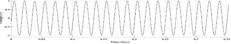
When the inverter is operating with load, 48-step is observed on the voltage waveform. The voltage becomes smoother because harmonics are filtered by the transformer leakage reactance. Initially VSC is operated with resistive load to study the operational characteristic of voltage source converter. Three phase output phase voltage(V abc) and phasecurrent(l abc) waveforms are shown in the Fig.3 and
Fig.4,respectively.
Fig. 3 Output voltage of VSC (V abc)
Fig. 4 Output Current of VSC (I abc)
VI.PRINCIPLE OF OPERATION OF STATCOM
The function of the STATCOM is to inject the current at the point where it is connected. STATCOM is shunt connected device, which injects the current into the system. The injecting current into the system is two different ways. one is the injected current leads the system voltage, the STATCOM operates in capacitive mode of operation. In this mode of operation, the STATCOM injects the reactive power into the system. If the STATOCM injected current is lags the system voltage, it operates in inductive mode of operation. In this mode of operation, it observes the reactive power from the system. Comparison the injected current and system voltage is shown in fig. 5.
Fig. 5 Comparison between STATCOM and System voltage
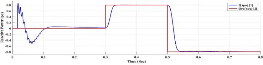
VII.VAR CONTROL IN STATCOM MODE
In this mode of operation, the STATCOM is operated as a variable source of reactive power. Initially, reactive power Q is maintained at zero, then at T1=0.3 sec, Q is increased to +0.8pu. in this mode, the STATCOM absorbs the reactive
power and at T2=0.5 sec, Q is reversed to -0.8pu. In this condition the STATCOM generating reactive power. From
the fig. first trace around t=0.5 sec when Q is changed from +0.8pu to -0.8pu. When Q=+0.8pu, the current flowing into the STATCOM is lagging voltage, indicating that STATCOM is absorbing reactive power. When Q ref is changed from
+0.8 to -0.8, the current phase shift with respect to voltage changes from 90 degrees lagging to 90 degrees leading within one cycle. This control of reactive power is obtained by varying the magnitude of the secondary voltage Vs generated by the shunt converter while keeping it in phase with the bus B6 voltage V p. This change of Vs magnitude is
performed by varying the DC bus voltage. When Q is changing from +0.8pu to -0.8pu,
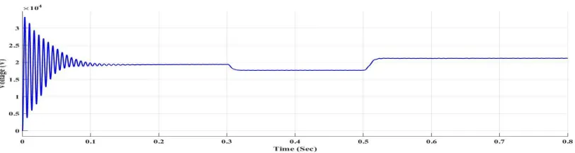
Fig. 7 DC link Voltage of a IUPFC Transmission System
The above Fig. 7 show VDC increases from 17.5 kV to 21 kV when the controller is operating in STATCOM mode of
operation. I.e. STATCOM is operating in VAR control mode of operation.
VIII.OPERATIONOFTHESSSC
The function of SSSC is to inject the voltage in series to the transmission line system. This injected voltage will be a controllable in magnitude and phase angle. The injected controllable voltage will be injected into two ways. One is the injected voltage leads the system line current, then the SSSC is acts in capacitive mode of operation. In this mode of operation, the series connected device injects the reactive power into the system. If the injected voltage is lags the system voltage, then it acts in inductive mode of operation. In this mode of operation, it observes the reactive power from the system.
IX.CLOSED LOOP RESPONSE OF THE IUPFC
IUPFC is modelled to control the power flow on the parallel transmission lines. It is the combination of two converters namely shunt converter (STATCOM) and series converter (SSSC). Shunt converter is connected in shunt with the transmission line-1, its function is to maintain the DC link voltage constant and control the bus voltage independently. Series converter connected in series with the transmission line-2, its function is to control the active and reactive power independently. The dynamic behaviour of the controller is observed by applying the following inputs. (a) Impact of step change in reference values of the Real power of line-Ion IUPFC performance. (b) Impact of step change in reference reactive power of line-lon IUPFC performance.
X.EFFECTOFSTEPCHANGEINREFERENCEVALUESOFREALPOWEROFTRAMSMISSIONLINES
ONIUPFCPERFORMANCE
The reference value of real power is remains at P ref = 8pu during the time period 0 < t < 0. 7 sec and the at the time
t=0.7 sec the reference value is suddenly increased to P ref = l0pu, throughout the period the reference value of the
reactive power is maintained at Q ref =-0.6pu. The actual power flow on the line-1 for the step change in reference value
Fig.8 Dynamic Response of IUPFC (Active Power)
XI.IMPACTOFSTEPCHANGEINREFERENCEVALUESOFREACTIVEPOWEROFTRANSMISSION
LINESONIUPFCPERFORMANCE
During time period 0 < t < 1. 4 sec the reference value of reactive power is maintained at Qref= - 0.6pu, and
the time t=1.4sec the reference value is increased to Qref = +0.5pu, throughout the period the reference value
of the real power is maintained at Pref=8pu. The actual power flow on the line-1 for the step change in reference value is shown in the Fig.9.The corresponding DC link voltage and line voltage of the transmission -2. From the plot, it is inferred that the power flows on the line-l follow the reference values. DC link voltage is maintained constant for the step change in the reference value of reactive power, similarly the line voltage of the line-2 is also regulated at 1pu.
Fig. 9 Dynamic Response of IUPFC (Reactive power)
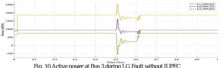
XII.TRANSIENT ANALYSIS ON PARALLEL TRANSMISSION LINES DURING LG & LLG FAULT WITHOUT CONTROLLER
The Fig. 10shows the bus 3 active power during the LG fault condition without IUPFC. The fault is applied at 0.5 sec and removed at 0.6 sec. During the fault condition the oscillations of L1is raised above the
2500MW active power after the fault is removed, the oscillations are last up to 160 msec.
Fig. 11Active Power at Bus 3 during LLG Fault without IUPFC
The Fig. 11shows the bus 3 Active Power during the LLG fault condition without IUPFC. The fault is applied at 0.5 sec and removed at 0.6 sec. During the fault condition the oscillations of L1 is raised above the
2500MW active power. After the fault is removed, the oscillations are last up to 160 msec.
XIII.PERFORMANCE OF IUPFC DURING LG FAULT
Fig. 12 Active Power at bus 3 during LG Fault with IUPFC
The above Fig.12shows the bus 3 active power during the LG fault condition with IUPFC. The fault is applied at 0.5 sec and removed at 0.6 sec. During the fault condition the oscillations are raised nearer to 1500MW active power only when compared to LG fault without controller. Whereas in without controller the active power oscillations are raised above 2500 MW. After the fault removed, the oscillations are last up to 160 msec. By using IUPFC the power oscillations are damped minimum when compared to the oscillations without IUPFC.
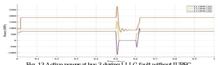
XIV.PERFORMANCEOFPARALLELTRANSMISSIONLINESDURINGLLLGFAULTWITH
The above Fig. 13 shows the bus 3 active power during symmetrical fault LLLG fault condition without IUPFC. The fault is applied at 0.5 sec and removed at 0.6 sec. During the fault condition the oscillations of L1 is raised above the 2500MW active power. After the fault removed the oscillations are last up to 160
msec.
Fig. 14 Active power at bus 3 during LLLG Fault with IUPFC
The above Fig. 14 shows the bus 3 active power during symmetrical fault LLLG fault condition with IUPFC. The fault is applied at 0.5 sec and removed at 0.6 sec. During the fault condition the oscillations are raised above the 1500MW active power only when compared to without IUPFC.So, this show that the oscillations are damped with IUPFC when compared to without IUPFC. After the fault removed the oscillations are last up to 160 msec.
XV.CONCLUSION
This paper deals with the development of Simulink Models of Voltage Source Converter (VSC) applications in the FACTS type power transmission systems. It includes the Simulink Model of a Three-phase 48-Pulse Voltage Source Converter that is used to build the STATCOM, SSSC and IUPFC applications for transmission systems. These, FACTS devices improve the power transfer capability on existing transmission systems and also improve the oscillation damping of the system.The IUPFC is a FACTS device used for controlling power flow on the parallel transmission lines. The entire FACTS device is capable of exchanging the real and reactive power with the system. The performance of the IUPFC on the parallel transmission lines are demonstrated. The results of simulation show the effectiveness of the IUPFC which controls the impedance of the transmission line and also damp the power oscillations during the fault condition. Thus, IUPFC is effective in controlling the active and reactive power and also reduce the power oscillations during faulty conditions and increases the stability.
REFERENCES
[1] N. G. Hingorani and L. Gyugyi, "Understanding FACTS: Concepts and Technology of Flexible AC Transmis sion System," New York, NY: IEEE press, 2000.
[2] V. K. Sood, "Static Synchronous Series Compensator Model in EMTP," ICCC Canadian Conference on Electrical and Computer Engineering, Vol. 1, No.3, pp. 207-211,Winnipeg, May 2002.
[3] S. Salem and V.K. Sood, "Modeling of Series Voltage Source Converter applications with EMTP-RV," International Conference on Power System Transient (lPST'05), Montreal, June 19-23, 2005.
[4] L. Gyugyi, K. K. Sen, and C. D. Schauder, "The Interline Power Flow Controller Concept: A New Approa ch to Power Flow Management in Transmission Systems," IEEE Transactions on Power Delivery, Vol. 14, No. 3, July 1999.
[5] S. Teerathana, A. Yokoyama, Y. Nakachi, and M. Yasumatsu, "An Optimal Power Flow Control Method of P ower System
by Interline Power Flow Controller (IPFC),"in Proc. 7th International Power Engineering Conference,Singapore, pp. 1-6, 2005.
[6] X. P. Zhang, "Modeling of Interline Power Flow Controller and The Generalized Unified Power Flow Con troller in Newton Power Flow ", Proc. Institution Electrical Engineering, Generation, Transmission, Distributio n, Vol. 150, No. 3, pp. 268-274, May 2003.
[7] Jianhong Chen, T.T. Lie, and D.M. Vilathgamuwa," BasicControl of Interline Power Flow Controller," IEEE PowerEngineering society winter meeting, vol. 1, pp. 521-525,January 2002.
[8] Ali Ajami and Abdel-rahim Kami, "Modeling and Controlling of Interline Power Flow Controller Based Current-Source Converter," Second International Conference on Computer and Electrical Engineering 2009, Vol. 1, pp. 353-357. January 2010.
[10]H. Fujita, Y. Watanabe and H. Akagi, “Dynamic Control and Performance of a Unified Power Flow Controller for Stabilizing an AC Transmission System,” IEEE Trans. Power Elect, Vol. 21, no. 4, pp.1013-1020, July,2006.
[11]B. Kawkabani, Y. Pannatier and J. J. Simond, "Modeling and Transient Simulation of Unified Power Flow Controllers (UPFC) in Power System Studies," 2007 IEEE Lausanne Power Tech, pp. 333-338, Lausanne, July 2007.