Comparisons of Different Algorithms for
Speech Processing
Dr.V.G. Sangam1, Siri Dayanand2
Professor and Head of Dept., Dayananda Sagar College of Engineering, Bangalore, India1
PG Student [Microelectronics and Control Systems], Dayananda Sagar College of Engineering, Bangalore, India2
ABSTRACT: The Kalman filter-based beam former (KFB) is a recursive Bayesian method for implementing the beam former. We adopt the KFB framework to the task of speech extraction. We formalize the KFB with a set of linear constraints and present its equivalence to the linearly constrained minimum variance (LCMV) beam former. We further show that the KFB provies better results compared to LCMV and MVDR beamforming techniques.
.
KEYWORDS: Kalman filter-based beamformer (KFB), linearly constrained minimum variance beamformer (LCMV), minimum variance distortion less response (MVDR)..
I.INTRODUCTION
The term beamforming [1] evolves from the fact that early spatial filters were designed to form pencil beams in order to receive signals from a desired direction and reject signals from other direction. The desired signals may also be subject to distortion imposed by the acoustic room impulse responses (RIRs). A linearly constrained minimum variance (LCMV) [2] beamformer is designed for extracting the desired signals from multimicrophone measurements. The beamformer satisfies two sets of linear constraints. One set is dedicated to maintaining the desired signals, while the other set is chosen to mitigate both the stationary and nonstationary interferences.
The operation of MVDR [3] is based on finding the optimum weight to direct the main lobe beam to the desired user location with unity gain. The MVDR beam former does not require the knowledge of the directions of the interferences for weight vector calculation. It requires only the direction of the desired signal. Thus, the beamformer weights are selected by minimizing the mean output power while maintaining unity response in the look direction. The constraint ensures that the signal passes through the beamformer undistorted.
Kalman Filter [4] is an adaptive least square error filter that provides an efficient computational recursive solution for estimating a signal in presence of noises. It is an algorithm which makes optimal use of imprecise data on a linear (or nearly linear) system with errors to continuously update the best estimate of the system's current state.
In this paper we will be comparing the algorithms of LCMV beamforming and MVDR beamforming and showing that KFB provies better results.
II.LCMV BEAMFORMER
Linearly constrained minimum variance (LCMV) beamformer is a conventional and powerful tool for signal enhancement in multiple sources cases. The conventional LCMV beamformer is a kind of closed form LCMV (CFLCMV) beamformer which is obtained by directly using Lagrange multipliers. As a generalized minimum variance distortion-less response (MVDR) beamformer, the conventional
LCMV beamformer minimizes the array output power while maintaining a constant response in the direction of the signal of interest (SOI).
Consider D point source signals (including signals and interferences) impinging on an array comprising M sensors with an arbitrary geometry from directions θ1,θ2,···,θD The output ( ) of array beamformer can be expressed as:
( ) = ( ) (1)
(MVDR) beamformer, the objective is to minimize the array output energy, subject to a linear constraint on the desired direction-of-arrival (DOA), i.e.,
minimize ( ) =
subject to ( ) = 1 (2)
where = { ( ) ( )is the covariance matrix of the received signal x with E {·} being the expectation operator. For LCMV-type beamformers, w is the solution to the following multiple linearly constrained optimization problem:
minimize ( ) =
subject to = (3)
where C is the aforementioned constraint matrix and f is a constraint vector. For example, if we need to generate unit
gains in L DOAs θi (i = 1,2,···,L) while forming nulling in other DOAs, the constraint matrix and constraint vector can be expressed as:
C = [a(θ1),···,a(θL),a(θL+1),···,a(θD)] (4)
and
= [1, … 1 0, … 0]T
(5) respectively. Based on (3), (4), and (5), by using Lagrange multipliers technique, one can obtain a closed-form solution of the optimal weight vector w as follows:
= ( ) (6)
Equation (6) is the well-known optimal weight vector of LCMV beamformer and it is a closed-form solution to (3).
III.MVDR BEAMFORMING
The MVDR design principles are reviewed in this section based on the point source narrowband signal model. It is also assumed for simplicity that an antenna array has linear geometry and it consists of omnidirectional antenna elements. Consider a linear antenna array with M omni-directional antenna elements. The narrowband signal received by the antenna array at the time instant k is mathematically represented as:
( ) = ( ) + ( ) + ( ) (7)
where ( ), ( ) and ( ) denote the Mx1 vectors of the desired signal, interference, and noise, respectively.
The desired signal is assumed to be uncorrelated with the interferers and noise, while the received signal is assumed to be zero-mean and quasi-stationary. Under the aforementioned point source assumption, the desired signal ( ) is expressed as
( ) = ( ) ( ) (8)
where s (k) is the signal waveform and ( ) is the steering vector associated with the desired signal. This steering vector is a function of array geometry as well as source and propagation media characteristics such as, for example, the desired source direction-of-arrival (DOA) .
The beamformer output at the time instant k can be written as:
( ) = ( ) (9)
where w is the Mx1 complex weight (beamforming) vector of the antenna array and stands for the Hermitian transpose.
In the case of a point source, under the assumption that the steering vector ( )is known precisely, the optimal weight vector w can be obtained by maximizing the beamformer output SINR given as
⍙ [| | ]
[| ( )| ]=
| ( )|
(10)
Where ⍙ [| ( )| ] is the desired signal power,
⍙ [( ( ) + ( ))( ( ) + ( )) ]is the MxM interferenceplus-noise covariance matrix, and E[.] denotes the expectation operator.
min such that ( ) = 1 (11) The solution of the optimization problem (11) is well known under the name MVDR beamformer and it is given
= ( ) (12)
where denotes the inverse of a positive definite square matrix and = ( ) ( )is the normalization constant
that does not affect the output SINR (10) and, therefore, will be omitted.
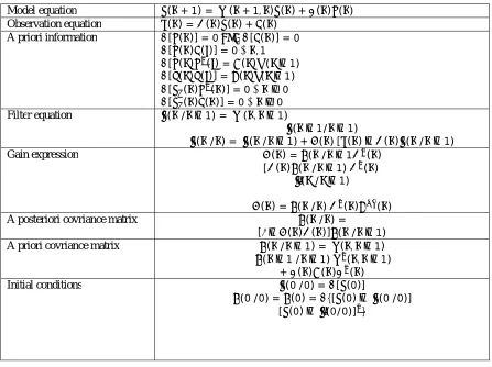
IV.KALMAN FILTER BASED BEAMFORMER
TABLE 1: Kalman filter equations Model equation ( + 1) = ( + 1, ) ( ) + ( ) ( )
Observation equation ( ) = ( ) ( ) + ( )
A priori information [ ( )] = 0 [ ( )] = 0 [ ( ) ( )] = 0 ∀ , 1
[ ( ) ( ) = ( ) ( −1)
[ ( ) ( )] = ( ) ( −1)
[ ( ) ( )] = 0 ∀ ≥0
[ ( ) ( )] = 0 ∀ ≥0
Filter equation ( / −1) = ( , −1)
( −1/ −1)
( / ) = ( / −1) + ( )[ ( )− ( ) ( / −1)
Gain expression ( ) = ( / −1 ( )
[ ( ) ( / −1) ( )
( / −1)
( ) = ( / ) ( ) ( )
A posteriori covriance matrix ( / ) =
[ − ( ) ( )] ( / −1)
A priori covriance matrix ( / −1) = ( , −1)
( −1/ −1) ( , −1)
+ ( ) ( ) ( )
Initial conditions (0/0) = [ (0)]
(0/0) = (0) = {[ (0)− (0/0)]
[ (0)− (0/0)] }
The AR process is represented by the equation (13)
( ) =− ∑ ( − ) + ( ) (13)
In this equation ( ) is the zero−mean white Gaussian noise and ( ) is the signal at an instant k. A state space illustration is adopted to highlight the criterions that which requires establishment, particularly the predictive coefficients { }∈[ ,…, ]. The state vector ( ) is later accepted such that the elements { ( )}∈[ ,…, ]correspond to the
prediction coefficients:
( ) = ( ) ⋮ ( )
= ⋮ (14)
however we also observe that:
We later design the observation vector by keeping the p values of the below remarks:
( ) = [− ( −1) …− ( − )] (16)
As we consider the model to be stationary, parameters { }∈[ ,…, ] can be assumed constant. Hence the equation (17)
and (18) describes the state space model:
( + 1) = ( ) (17)
( ) = ( ) ( ) + ( ) (18)
Regarding the illustartions in equations
( + 1) = ( + 1, ) ( ) + ( ) ( ) (19)
( ) = ( ) ( ) + ( ) (20)
(19)and (20), the equations (21) and (22) directs to the below mentioned matrices preferences:
( ) = 0 ( + 1, ) = (21)
As the deviation of the supplement noise is = 1, same equations depicts both the the Kalman filter and the recursively least square algorithm.
APPLICATION TO SPEECH ANALYSIS
speech signal modelled by an model:
( ) + ( −1) +⋯+ ( − ) = ( ) (13)
where ( ) denotes the sample of the speech. the prediction error is:
( ) = ( )− ( ) ( ) (22)
and the variation norm of the parameter vector is:
( ) = ( ) ( )− ( −1) ( −1) (23)
Both the covariance and autocorrelation methods gives rise to similar parameters as predicted by the kalman filter.
V. RESULT AND DISCUSSION
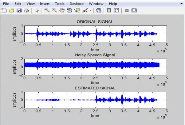
When the input signal is applied to the kalman filter the estimated output is shown in the fig1.
Fig. 2 mean square error plot of Kalman filter
In the fig 2, it shows the mean square error of the signal of Kalman filter.
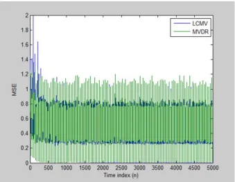
Fig 3, shows the mean square error of LCMV and MVDR Beamforming
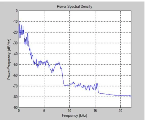
Fig4 Power spectral density plot of Kalman filter
Fig 4 shows the power spectral density of the Kalman filter.
Fig 5 Power spectral density plot of LCMV and MVDR
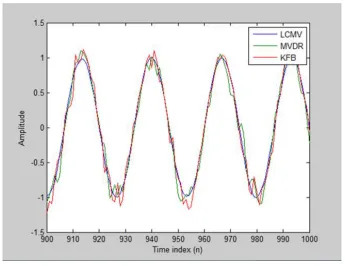
Fig 6 Plot of different algorithms
Figure 6 shows the output plot of the different algorithms hence proving that Kalman filter shows better results compared to LCMV and MVDR.
VI.CONCLUSION
Comparing fig 2 and fig 3 Kalman filter has a mean square of 1.8 while LCMV and MVDR have 2, showing Kalman filter has less mean square error. The power spectral density plot in fig 4 and fig 5 shows that at 10KHz the Kalman filter becomes while the LCMV and MVDR is still varying. From fig 6 we can also conclude that the KFB is showing better results of the speech extracted from a noise environment than the LCMV and MVDR Beamforming methods.
REFERENCES
[1] Barry D. Van Veen and Kevin M. Buckley “Beamformimg: A versatile approach to spatial filtering” IEEE ASSP MAGZINEapril 1988. [2] ShmulikMarkovich, Sharon Gannot, Israel Cohen “Multichannel Eigenspace Beamforming in a Reverberant Noisy Environment With Multiple Interfering Speech Signals”IEEE transactions on audio, speech, and language processing, vol. 17, no. 6, august 2009.
[3] ReetaGaokar, Dr. Alice Cheeran “Performance Analysis of Beamforming Algorithms” IJECT Vol. 2, Issue 1, March 2011
[4]DaniCherkassky and Sharon Gannot “New insights into the Kalman filter beamformer: Applications to speech and robustness” IEEE signal processing letters, vol. x, no. y, january 2016
[5] Y. H. Chen and C. T. Chiang, “Adaptive beamforming using the constrained kalman filter,” IEEE Trans. Antennas Propagat., vol. 41, no. 11, pp. 1576–1580, 1993.
[6] S. Gannot, D. Burshtein, and E. Weinstein, “Signal enhancement using beamforming and nonstationarity with applications to speech,” IEEE
Trans. Signal Process., vol. 49, no. 8, pp. 1614–1626, 2001.
[7] S. Markovich-Golan, S. Gannot, and I. Cohen, “Multichannel eigenspace beamforming in a reverberant noisy environment with multiple interfering speech signals,” IEEE Trans. Audio, Speech, Lang. Process., vol. 17, no. 6, pp. 1071–1086, 2009.
[8] S. Doclo and M. Moonen, “Gsvd-based optimal filtering for single and multimicrophone speech enhancement,” IEEE Trans. Signal Process., vol. 50, no. 9, pp. 2230–2244, 2002.
[9] S. Gannot and I. Cohen, “Adaptive beamforming and postfitering,” Springer Handbook of Speech Processing, New York, NY, USA: Springer, 2007.
[10] S. Markovich-Golan, S. Gannot, and I. Cohen, “Subspace tracking of multiple sources and its application to speakers extraction,” IEEE Int.
Conf. Acoustics Speech and Signal Processing (ICASSP), 2010, 2010, pp. 201–204
[11] D. Simon, “Kalman filtering with state constraints: A survey of linear and nonlinear algorithms,” IET Control Theory Applicat., vol. 4, no. 8, pp. 1303–1318, 2010.
[13] J. S. Hu and M. T. Lee, “Norm constrained capon beamforming using multi-rank signal models with kalman filter implementation,” IEEE
Trans. Antennas Propagat., vol. 62, no. 9, pp. 4574–4583, 2014.
[14] C. Paleologu, J. Benesty, and S. Ciochina, “Study of the general kalman filter for echo cancellation,” IEEE Trans. Audio, Speech, Lang. Process., vol. 21, no. 8, pp. 1539–1549, 2013.