IJEDR1402125
International Journal of Engineering Development and Research (www.ijedr.org)2071
Modified Booth Encoder Comparative Analysis
1
Dinesh C Karen,
2Nabila Shaikh
1
M. E. Scholar, 2Associated professor LJIET, Gujarat Technological University-Ahmedabad
1[email protected], 2[email protected]
Abstract— In recent years so many new technologies have been developed. Most of the technology has the main importance is regarding to the speed, accuracy, less power consumption. Most of the DSP processors, Math processors and various scientific applications require Booth multipliers. In the booth multiplier the booth encoder plays an important role. It occupies most of the area and also generates the signals which must be useful for generating the partial product. So booth encoder must accurate as much possible. In our paper we mainly concentrate on the delay of each signal and the number of transistors we used. Obviously so many way to implement this but we have chosen the CMOS technique which is comparatively faster than traditional ones. The recent time is of nanometer technology so we have chosen 45nm technology. The tool which we have used is TANNER EDA 15.
Keywords— booth encoder, radix 4, CMOS, 45nm, TANNER, Simulation Results
________________________________________________________________________________________________________
I. INTRODUCTION
High speed multiplication is an efficient scenario in many applications. As per requirement the booth multiplier is common approach to the VLSI design of high computing multiplier used in many applications like DSP processors, multimedia and 3-D graphics [1]. Multiplier is one of the important elements in above devices which mainly focus on the speed and the area which it occupies. Fast multipliers are essential parts of digital signal processing systems. The speed of multiplier operation is of great importance in digital signal processing as well as in the general purpose processors today. The basic multiplication principle is twofold i.e., evaluation of partial products and accumulation of the shifted partial products. Basic multiplication can be realized by shift add algorithm by generating partial product. Thus multiplication is proportional to the number of partial product to be added. In conventional multiplier the number of partial product that are added will be determined by the number of bits. The bits which are used by the multiplier or multiplicand. As much as the numbers of multiplier or multiplicand are big the partial product would be also big. So time will be taken to produce the product. The will be also more. So instead that one of the algorithms is used to reduce the partial product is booth encoding multiplier[3]
Booth encoding multiplication is able to reduce the number of partial product being encoded to increase the speed of binary multiplications. Radix-4 booth encoding multiplier reduces the number of partial product by half. This is able to increase the speed.
Booth encoder can be designed in many ways. Two kind of booth encoder has been shown here. Generally AND, XOR, Inverter gates has been used here. Each of them produces the output according to their inputs.
II. RADIX 4
One of the solutions of realizing high speed multipliers is to enhance parallelism which helps to decrease the number of subsequent calculation stages. The original version of the Booth algorithm (Radix-2) had two drawbacks. They are: (i) the number of add subtract operations and the number of shift an operation become variable and becomes inconvenient in designing parallel multipliers. (ii) The algorithm becomes inefficient when there are isolated 1‟s. These problems are overcome by using modified Radix 4[4]
Booth algorithm which scans strings of three bits is given below: 1) Extend the sign bit 1 position if necessary to ensure that n is even. 2) Append a 0 to the right of the LSB of the multiplier. 3) According to the value of each vector, each Partial Product will be 0, +M,-M, +2M or -2M. The negative values of B are made by taking the 2‟s complement and in this paper Carry-look-ahead (CLA) fast adders are used. The multiplication of M is done by shifting M by one bit to the left. Thus, in any case, in designing n-bit parallel multiplier, only n/2 partial products are produced.[4]
-1 0 1 0 0 -1 1 0 -1 1 -1 1 0 0 -1 0
-2 2 -1 2 -1 -1 0 -2 Recoded Radix4
IJEDR1402125
International Journal of Engineering Development and Research (www.ijedr.org)2072
pair of bits. Remember that the leftmost bit has 2X the weight of the rightmost bit in each pair.Table 1 radix 4 booth recoding i+1 i i-1 i+1 i i/2 Explanation
0 0 0 0 0 0 No string of 1s in sight 0 0 1 0 1 1 End of strings of 1s
0 1 0 0 1 1 Isolated 1
0 1 1 1 0 2 End of string of 1s 1 0 0 -1 0 -2 Beginning of string of 1s 1 0 1 -1 1 -1 End a string, begin a new
one
1 1 0 0 -1 -1 Beginning of string of 1s 1 1 1 0 0 0 Continuation of string of 1s Addition, A m = Ym-1 ⊕ Ym;
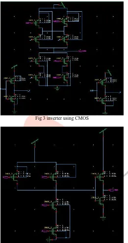
Fig 1 III. BOOTH ENCODER
BY CHO
Fig 2 Booth encoder
In 2003, Cho, et al., developed a new Booth encoder and the selector with a fewer number of components. They developed a new encoder based on the modified Booth algorithm. In their design they described Booth function as three basic operations, which they called „direction‟, „shift‟, and „addition‟ operation. Direction determined whether the multiplicand was positive or negative, shift explained whether the multiplication operation involved shifting or not and addition meant whether the multiplicand was added to partial products [2]. The expressions for Booth encoding were stated Below as:
IJEDR1402125
International Journal of Engineering Development and Research (www.ijedr.org)2073
Shift, Sm = Ym-1 · (Ym+1 ⊕ Ym) + Ym-1’ · (Ym+1 ⊕ Ym)Fig 3 inverter using CMOS
Fig 4 XOR using CMOS
Table 2: Truth table for booth encoding Ym+1 Ym Ym-1 Booth op. Dir. Shft Add.
0 0 0 0x 0 0 0
0 0 1 1x 0 - 1
0 1 0 1x 0 - 1
0 1 1 2x 0 1 0
1 0 0 -2x 1 1 0
1 0 1 -1x 1 - 1
1 1 0 -1x 1 - 1
1 1 1 -0x 1 0 0
PROPOSED BOOTH ENCODER
IJEDR1402125
International Journal of Engineering Development and Research (www.ijedr.org)2074
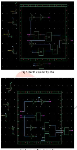
Figure 4: AND using CMOS.Fig 5 Booth encoder by cho
Fig 6 proposed booth encoder
Now from the booth encoder that is given by cho the truth table is shown in the following manner. The direction, shift and the addition signals will be given in the table.
Table 3: Truth table for proposed booth encoder
X1 X0 X-1 POUT QOUT ROUT
0 0 0 0 0 0
0 0 1 0 1 0
0 1 0 0 1 1
0 1 1 0 0 1
1 0 0 1 0 1
1 0 1 1 1 1
1 1 0 1 1 0
IJEDR1402125
International Journal of Engineering Development and Research (www.ijedr.org)2075
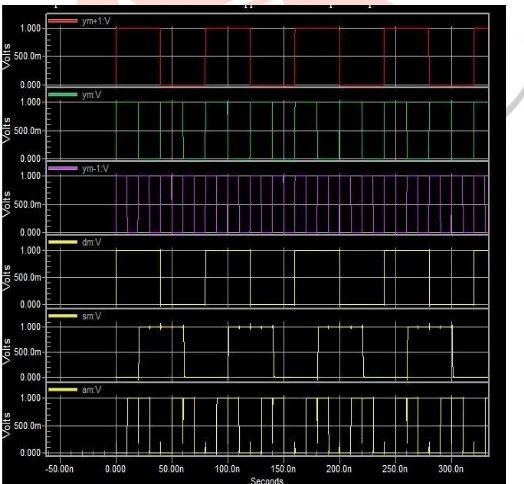
IV. SIMULATION RESULTSFig 7 Transient Response of booth encoder by CHO
As shown in the figure 7 and 8 the transient response of the booth encoder by cho and the proposed booth encoder respectively. In figure 7 total six wave forms are shown. Red, green and violet colors are indicated the inputs and the yellow three waveforms shows the three signals as an output. This thing ensures the truth table 2. On the other way the output wave form of proposed booth encoder is shown and it ensures the truth table 3.
.
Fig 8 transient response of proposed booth encoder
Table 4: The comparative analysis modified booth encoder Booth encoder by Proposed booth
Cho Encoder
Number of transistors 60 38
IJEDR1402125
International Journal of Engineering Development and Research (www.ijedr.org)2076
V. CONCLUSIONFrom the simulation of the both encoder one thing is clear that proposed booth encoder gives faster result comparatively. Mainly our goal is achieved by this method. As we can see that CMOS is obviously faster than conventional method but also much improvement are available. As numbers of transistors are reduce then the area also occupies less. There is less amount of delay in the transient response for all three control signals and make the booth encoder much faster. Also the power dissipation would be the another phenomenon where we can achieved the superiority.
REFERENCES
[1] A.D.Booth” a signed binary multiplication technique” quatarley j. mechanical and applied math vol 4,1951
[2] Ki-seon Cho, Jong-on Park, Jin-seok Hong, Goang-seog Choi “54x54-bit Radix-4 Multiplier based on Modified Booth Algorithm”,GLSVLSI,2003.
[3] Kelly liew suet sweet, Lo hai hiung, “ performance review of radix-based multiplier design”, ICIAS2012
[4] Jackuline Moni D, Anu Priyadharsini K.,” design of low power and high performance radix-4 multiplier”,IEEE conferences