ABSTRACT
DUDANI, AJAY B. User Interface Softbots. (Under the direction of Dr. Robert St.
Amant).
A user interface softbot is a software agent that controls an interactive system through its
graphical user interface, relying on visual information of the system rather than an
application programming interfaces or access to source code. We have developed a
prototype system that facilitates the use and extension of interface softbots, reforming the
programming process and making it easier for new developers. We present the JSegMan
substrate that facilitates the representation and identification of the conventional
graphical user interface. The JSegMan substrate consists of sensors, effectors and
framework for an agent that can control the user interface environment. Using image
processing the sensor builds a representation of the desktop’s visual interface. The
effector module generates mouse and keyboard gestures to control the desktop
environment. The sensor and effector modules work as eyes and hands of a controller
application that can be tailored for a given application domain. We also present three
applications - MSN Chatbots, the classical Blocks World problem solver and a GUI
testing tool that use the JSegMan substrate and demonstrates applicability of JSegMan in
use with off-the shelf applications, PDDL based planners and in testing environment
USER INTERFACE SOFTBOTS
by
AJAY B. DUDANI
A thesis submitted to the Graduate Faculty of
North Carolina State University
in partial satisfaction of the
requirements for the Degree of
Masters of Science in Computer Science
Department of Computer Science
Raleigh, NC
September 10, 2003
APPROVED BY:
________________________ _______________________ Dr. Michael Young Dr. Munindar Singh
To my parents and family,
for their guidance, support,
Biography
Ajay Dudani was born on February 27, 1980 in Ahmedabad, India. He graduated with a
Bachelor of Engineering degree in Information Technology from Nirma Institute of
Technology, Gujarat University, India in June 2001. He worked as an Engineering
Trainee with Motorola India Electronics Limited, Bangalore, India as part of his final
semester project. He then joined the Masters program in Computer Science at North
Carolina State University. While working towards the Masters degree, he also worked as
Acknowledgements
I would like to thank my advisor, Dr. Robert St. Amant, for his continuous guidance,
mentoring and support. This work could not have been a success without his insightful
remarks and advice. I also extend my gratitude to Dr. Michael Young and Dr. Munindar
Singh for being on my advisory committee and providing me with valuable suggestions.
I thank my colleagues and friends Kunal Shah and Sameer Rajyaguru for sharing their
creative ideas and providing me with an excellent research environment.
My thanks go to my friends Sameer Desai, Kurang Mehta, Arnav Jhala, Nirmit Desai,
Japan Doshi, Shalin Dalal, Vimal Suba and Ajit Jain. Their delightful company has
brought some very good times during my Masters at NC State University and helped me
maintain a work/play balance. Special thanks to Jalpa Ramwani and Reshma Mehta for
Table of Contents
LIST OF TABLES... VII
LIST OF FIGURES...VIII
LIST OF PSEUDO CODE... IX
CHAPTER 1 ... 1
INTRODUCTION... 1
Goals... 5
Outline ... 6
CHAPTER 2 ... 8
RELATED WORK... 8
Agents ... 8
Planners... 10
Planning agents for interface agents ... 17
GUI Testing... 18
CHAPTER 3 ... 20
SYSTEM DESIGN AND IMPLEMENTATION... 20
JSegMan sensor and effector subsystems ... 24
Description of system files and API's... 34
JSegMan as a programming environment ... 40
JSegMan interaction with PDDL based planners... 44
CHAPTER 4 ... 50
EVALUATION... 50
MSN Chatbot... 54
Blocks Work Problem in PDDL ... 57
JSegMan in GUI testing environment ... 62
CHAPTER 5 ... 67
CONCLUSION... 67
Future Directions... 69
List of Tables
TABLE 1: INTRINSIC PROPERTIES OF AGENTS... 3 TABLE 2:EXTRINSIC PROPERTIES OF AGENTS... 3 TABLE 3: SIMILARITIES BETWEEN CLASSICAL PLANNING ASSUMPTIONS AND USER INTERFACE DESIGN
List of Figures
FIGURE 1: ARCHITECTURE OF SEGMAN... 21
FIGURE 2:ARCHITECTURE OF JSEGMAN... 23
FIGURE 3: ZOOMED IMAGE OF CHARACTERS ‘A’ AND ‘J’ SHOWING DIFFERENT GROUPS IN THE IMAGE... 27
FIGURE 4 (A) FIGURE 4 (B)... 28
FIGURE 5: WINDOWS “START” BUTTON... 32
FIGURE 6: ARCHITECTURE OF INTERACTION BETWEEN USER INTERFACE, JSEGMAN SUBSTRATE AND PDDL BASED PLANNER... 45
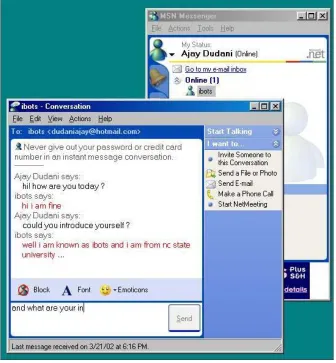
FIGURE 7: HUMAN USER END OF MSN CHATBOTS DEMONSTRATING JSEGMAN WORKING WITH OFF-THE-SHELF APPLICATION... 55
FIGURE 8: JSEGMAN END OF MSN CHATBOTS DEMONSTRATING JSEGMAN WORKING WITH OFF-THE-SHELF APPLICATION... 57
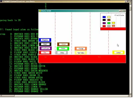
FIGURE 9: SOLVING BLOCKS WORLD PROBLEM WITH JSEGMAN AND PDDL BASED PLANNER... 59
List of pseudo code
LISTING 1: SYNTAX OF DOMAIN DEFINITION FILE IN PDDL... 13
LISTING 2:SYNTAX OF PROBLEM DEFINITION FILE IN PDDL... 14
LISTING 3: REPRESENTATION OF CARGO PROBLEM’S DOMAIN DEFINITION IN PDDL ... 15
LISTING 4: REPRESENTATION OF CARGO PROBLEM’S PROBLEM DEFINITION FILE IN PDDL... 16
LISTING 5: PIXEL NEIGHBOR NUMBERS FOR A SOLID 5-BY-5 BOX... 29
LISTING 6: PIXEL NEIGHBOR NUMBERS THAT UNIQUELY IDENTIFY THE SOLID 5-BY-5 BOX... 30
LISTING 7: PSEUDO CODE TO FIND ALL BUTTONS ON SCREEN... 33
LISTING 8: SAMPLE CODE TO POINT TO ALL OBJECTS ON SCREEN IDENTIFIED BY JSEGMAN SENSOR SUBSYSTEM... 44
LISTING 9: DEFINITION OF EXISTENCE OF A WINDOW OBJECT IN PDDL... 46
LISTING 10:PDDL ACTION DESCRIBING MOVING OF A WINDOW FROM ONE POSITION TO ANOTHER... 47
LISTING 11: PDDL ACTION DESCRIBING DRAG-AND-DROP BEHAVIOR OF DRAGGING AN ICON INTO A WINDOW ... 48
LISTING 12: : PDDL ACTION DESCRIBING DRAG-AND-DROP BEHAVIOR OF DRAGGING AN ICON OUT OF A WINDOW... 48
LISTING 13: PDDL FILE WITH A LIST OF ACTIONS TO BE PERFORMED SEQUENTIALLY... 49
LISTING 14:PDDL DOMAIN DEFINITION FILE FOR BLOCKS WORLD PROBLEM... 60
Chapter 1
Introduction
Over the period of last two decades, researchers have shown keen interest in the area of
software agents. Agents are commonly conceptualized as kinds of adaptive,
self-contained and intelligently executing software processes that encapsulate some state
information and can communicate with each other by exchanging messages. However,
many different projects use the term "agents" for somewhat different entities, ranging
from simple shell programs to systems incorporating real time planning and other
sophisticated planning.
The original sense of the word "agent" is of one person acting on behalf of someone else.
Agents can be as simple as subroutines, but typically they are larger entities with some
sort of persistent control. Although the traditional notion of an intelligent agent in AI is
that of a rational agent that has explicit representations of its goals and of its beliefs about
the world, the definitions of agent commonly used tend to depend on the background of
the researchers. Huhns and Singh [1] define agents as follows: "Agents are active,
persistent (software) components that perceive, reason, act and communicate."
The following scenarios exemplify some typical uses of agents: such examples have
does not enable the provision of all such facilities to an appropriate standard [3]. A user
wants to locate a published article, but knows only the title and author of the paper. The
user directs the Personal Assistant (PA) agent to find the article. The PA knows how to
find publications on the local network, but when unsuccessful it knows other useful ftp
sites and other intermediate agents. By contacting other agents, which in turn can contact
more agents and ftp sites, the PA will hopefully find an ftp site with a copy of the
requested article. It then arranges for transferring the article from the ftp site to the local
computer without any user intervention. Other routine processes can be automated in a
similar manner.
A user is occupied with some task on their computer, when their PA requests their
attention: an email message has arrived that contains submission results about a paper
they sent to an important conference, and the PA reasoned that the user might want to see
it as soon as possible. Since the paper has been accepted, the PA begins to look into
travel arrangements by contacting a number of databases and other networked
information sources and agents. A short time later, the PA presents the user with a
summary of cheapest and most convenient travel options.
Huhns and Singh [1] have identified the following as key characteristics of agents:
Intrinsic properties: Intrinsic properties of agents are the ones that are related to the
Table 1: Intrinsic properties of agents
Property Range of Values
Lifespan Transient to Long-lived
Level of Cognition Reactive to Deliberative
Construction Declarative to Procedural
Mobility Stationary to Itinerant
Adaptability Fixed to Teachable to Autodidactic
Modeling Of environment, themselves or other agents
Extrinsic properties: Extrinsic properties of an agent are defined in context of other
agents.
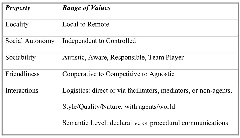
Table 2 : Extrinsic properties of agents
Property Range of Values
Locality Local to Remote
Social Autonomy Independent to Controlled
Sociability Autistic, Aware, Responsible, Team Player
Friendliness Cooperative to Competitive to Agnostic
Interactions Logistics: direct or via facilitators, mediators, or non-agents.
Style/Quality/Nature: with agents/world
Semantic Level: declarative or procedural communications
one step action to be performed on the direct manipulation interface. Lieberman [5]
defines interface agent to be a program that can also affect the objects in
direct-manipulation interface, but without explicit instructions from the user. In this way, the
interface agent is considered to be a robot whose sensors and effectors are input and
output capabilities of the interface. In this sense, such a robot is also referred to as
"softbots" [6]. Sometimes the interface agent may be anthropomorphically represented as
a face or animated character on screen, such as Clippy in the MS Office Suite.
Lieberman's work [5] led to development of Letizia, an autonomous interface agent for
Web browsing. Letizia is an autonomous agent that treats search through the Web space
as continuous and cooperative venture between the user and the agent. Letizia records
the URL surfed by the user and creates a complete profile of the user's interests. Letizia
is always active, searching the web space "near" the user's current position.
Work done by St. Amant et al [7] is based on the belief that "If you can see it, you should
be able to program it". It presents a radical approach to describe the user's intentions -
using the visual properties of the interaction elements themselves. Only recently has the
speed of image processing made feasible real-time analysis of screen images by
‘Programming by Example’ system. The foremost advantage of a Programming by
Example (PBE) system is that they can work from the visual appearance of the
application, and do not need to rely on the API's provided by applications. Thus a visual
PBE system, independent of the source code and API can work with off the shelf
Choosing an environment in which the agent will execute is an important decision for
agent developers [8]. In practical planing research, realistic environments create a
problem due to their dynamic nature. Realism of an environment can be a measure of
how close the environment is to the real environment or by seeing if the problems that
arise under controlled conditions are similar to those that an intelligent agent or a human
user may be able to solve in the real world. As opposed to realism is the problem of
tractability. It is not desirable to provide a highly realistic environment that is way too
difficult for the agent - to the extent that it hinders the agent.
In the ideal environment, researchers can pose realistic but tractable problems to an
agent, measure and evaluate its performance, and iteratively rework the environment to
explore more ambitious questions, all at a reasonable cost, time and effort [8].
Goals
This thesis focuses on the concept of ibots, interface agents that interact with software
applications through the graphical user interface, in the same way that human users do.
As a part of this work, we intend to develop a system that supports the control of an
application through its graphical user interface, bypassing its API. At first glance, it may
seem to be a waste of processing power, but visual manipulation has potential advantages
as well. For various reasons, some applications lack API and others allow only limited
control through API. In some cases like online applications, API cannot substitute for
other opportunities to extend off-the-shelf interactive applications that one cannot modify
directly as a developer.
Interface softbots usually act on the basis of their current and previous sensor readings.
Inspite of detailed image processing, a softbot's information about its environment may
be largely incomplete. This may be due to several reasons like imperfect sensors or the
agent not being aware of its initial state. We intend to extend our system to be able to
watch the users and learn from user actions. Such an adaptive learning agent will be able
to scale up to be able to work efficiently with many more applications and perform tasks
in the desktop environment.
Direct observation of user activities also leads to close collaboration. Once the agent and
user both know and intend that the other party observe their actions, collaboration
between both parties is possible. As a part of this work, we intend to extend JSegMan to
be able to help users based on its knowledge of desktop environment and by observing
user actions.
Outline
Chapter 2 gives a background on agents, planners and GUI testing in general. It also
presents a case of using planners for interface agents and presents an example of a
planning agent.
Chapter 3 briefly discusses the SegMan architectures and the moves on to a detailed
provided by the JSegMan substrate. It goes on to describe JSegMan as a programming
environment and representation of desktop environment in planning domain and
interaction between JSegMan and planning systems.
Chapter 4 evaluates the work presented in this thesis in terms of the link between user
interface and agents. It also evaluates the system developed in terms of its performance
and brings to light the limitations of the system. Later, it describes the applications built
based on JSegMan substrate.
Finally Chapter 5 concludes with a summary of contributions made as a part of this thesis,
Chapter 2
Related Work
Agents
An agent is any program that acts on behalf of the user in an assisting role rather than tool
in the manner of a conventional direct-manipulation interface. An agent should have
some level of intelligence, creativity, autonomy and initiative associated with it, in order
for the human to delegate responsibility of performing a task on an agent rather than
instruct it at every step. This property differentiates an agent from a tool [16]. This view
of an agent is controversial since different users may view a software interface either as
an agent or as a tool depending on their own view of how the software is acting. Another
aspect of agents is its autonomous behavior, as opposed to having a sequence of
interactions with the user.
Direct manipulation interfaces allow its users to directly manipulate the objects on the
screen. Each action of the user maps directly to change in state of an object on screen.
An interface agent can be defined as a program that can manipulate the direct
manipulation interface just like a human would. The interface agent reads the objects and
information presented by the direct manipulation interface, interprets it and acts on it
robot whose sensors and effectors are written in software, hence such agents are often
known as "softbots".
An agent can be considered having both characteristics of interface and autonomous
agent when there are some parts of the direct manipulation interface that the agent can act
on in an autonomous fashion. As a result, the end user would see the objects in direct
manipulation interface moving on their own, and the agent shall be able to identify the
changes in the interface on its own rather than being told by the end user.
Wooldrige and Jennings [17] divide agent related issues into three areas. Agent theory is
concerned with issues of what an agent and its formal mathematical representation and
reasoning. Agent architecture is related to software architectures of agents, and is
concerned with the problem of designing software implementation of agents that satisfies
agent theories. Finally, agent languages are related to software systems for programming
and experimenting with these agents. This thesis touches upon aspects of agent
architecture and agent languages.
Etzioni and Weld [18], at the University of Washington developed an AI agent that uses
the UNIX shell to interact with the World Wide Web. The agent's sensors included
UNIX utilities like netfind, gopher and archie and effectors included utilities like ftp,
telnet and mail. This softbot's planning environment included concepts of sub-goaling
and accepting incomplete specification of goals by searching for missing information
Over the last few years a lot of research has been done in agents related to Internet
activities like search agents and email agents to prevent spam. However interface agents
that directly manipulate an interactive environment using the interface have not been
exploited. Some similar work has been done in area of GUI testing, as discussed in
sections below, but the perspective of work done there has been done specifically keeping
GUI testing in mind instead of creating a generic system for a programmable interface
agent environment
Planners
The following section gives a brief introduction to planning and the different planning
techniques.
Automated plan generation techniques have been widely investigated and used in the
field of artificial intelligence. Planning systems require a starting state, a goal state and a
set of operations along with pre-conditions and post-conditions to those operations. The
planner then, by using various different algorithms, generates plans to move from initial
state to goal state [19].
Formally, a planning problem P(A, D, I , G) is a 4-tuple, where A is the set of operators,
D is the finite set of objects, I is the initial state of the system and G is the goal state of
the system. The solution to the planning problem is a plan: a tuple <S, O, L, B> where S
are the steps, O are ordering constrains on the elements of S, L are causal links
variables in S. Causal links are triples <Si, e, Sj>, where Si and Sj are parts of S. c is a
result of Si and also a pre-condition for Sj. Typically, the ordering constrains only induce
a partial ordering, so the set of solutions are all linearization of S consistent with O.
The actions that are results of planner executions have certain constrain on the
relationship among them. An action is an instance of operations with its variables bound
to values. STRIPS (Strategic Information and Planning System) is one such well-known
action representation language which specifies operators in terms of parameterized
pre-conditions and post-pre-conditions. STRIPS, however was developed over twenty years ago
and has limited expressive power. For example, no additional conditional or universally
quantified effects are allowed. Although, in theory, sets of STRIPS operators can be
combined together to encode various complex conditional effects, the number of
operators used to represent such effects increase exponentially very fast. A more
powerful representation is ADL [20], which allows conditional and universally quantified
effects in operators. This facility allows for defining operators in a more intuitive manner.
A more recent domain representation language is Planning Domain Definition Language
(PDDL), first used in AIPS'98 planning competition. The goals of designing the PDDL
language were to encourage empirical evaluation of planner performance, the
development of standard set of planning problems.
Recent developments in planning technology based on propositionalization of the search
space have greatly increased the efficiency of plan generation algorithms. A well-known
extends the ideas of the Graphplan system [23]. Graphplan introduced the idea of plan
generation by converting the representation of a planning problem into a propositional
encoding. Plans are then found by a means of search through a leveled graph, in which
even levels (0, 2, …, i) represent actions that might be performed at stage i of the plan,
and odd levels (1, 3, … i+1) represent actions that might be performed at time i+1. The
planners in Graphplan family, including FF, have shown increases in planning speeds of
several orders of magnitude on a wide range of problems as compared to earlier planning
systems [25].
Planning at one level of abstraction may be impractical for complex systems, which
consists of a large number of objects and operators. Techniques have been developed to
generate plans at multiple levels of abstraction; this is typically called Hierarchical Task
Network (HTN) planning [26] in which domain actions are modeled at different levels of
abstraction, and for each operator at level n, one specifies more "methods" at level n-1.
A method is a single-level partial plan and an action is said to "decompose" into its
methods. HTN planning focuses on resolving conflicts among alternative methods of
decompositions at each level.
PDDL is intended to express the "physics" of a domain i.e. what predicates there are,
what actions are possible, what the structure of compound action is, and what the effects
of actions are. The language supports the following syntactic features:
• Basic STRIPS-style actions
• Universal quantification over dynamic universes
• Domain action over stratified theories
• Specification of safety constraints
• Specifications of goals and sub-goals, thus providing hierarchical goals
support.
The domain specific knowledge is specified using predicates. Various actions to be
performed on domain are specified with actions. Usually a PDDL based planner takes
two files as input, one being the domain definition file consisting of domain predicates
and possible actions along with their pre conditions and post conditions. The second file
is the problem file, which consists of initial state of domain and final goal state of the
domain. The following is the syntax of domain definition file in PDDL:
(define (domain DOMAIN_NAME)
(:requirements [:strips][:equality][:typing][:adl]) (:types TYPE_1 TYPE_2 … TYPE_N)
(:predicates (PREDICATE_1 [?A1 ?A2 … ?AN]) (PREDICATE_1 [?A1 ?A2 … ?AN]) . . .)
(:action ACTION_1
[:parameters (?P1 ?P2 …?PN) ] [:precondition PRECOND_FORMULA] [:effect EFFECT_FORMULA] ) (:action ACTION_2
. . .)
The requirements keyword specifies the packages to be included for this planning
problem. Types specifies user defined domain specific types. Predicates are a set of
truth statements that govern the domain. Actions are operators available in the domain.
The actions have a precondition that specifies the predicates, which must be true, before
this operator is applied. The effect specifies the predicates that become true after this
operator is applied.
The syntax of a problem definition file is as under:
define (problem PROBLEM_NAME)
(:domain DOMAIN_NAME)
(:objects OBJ_1 OBJ_2 ... OBJ_N) (:init ATOM_1 ATOM_2 ... ATOM_N) (:goal CONDITION_FORMULA)
)
Listing 2: Syntax of problem definition file in PDDL
The problem definition file describes the problem to be solved. The init specifies the
predicates that are true at the beginning of the problem. The goal state specifies the
predicates that need to be true at the end of the problem.
Here is a listing of air cargo problem, to transfer cargo from one airport to another using a
plane. The domain definition file and problem files are listed below.
(:types Airport - Location PlaneType - Object CargoType - Object ) (:predicates
(In ?c - CargoType ?p - PlaneType) (At ?obj - Object ?loc - Airport) ) (:action Load
:parameters
(?c - CargoType ?p - PlaneType ?a - Airport) :precondition ( and (At ?c ?a)
(At ?p ?a)) :effect (and (not At(?c ?a))
(In ?c ?p) ) ) (:action Unload
:parameters (?c - CargoType ?p - PlaneType ?a - Airport) :precondition (and (In ?c ?p)
(At ?p ?a)) :effect (and (At ?c ?a )
(not (In ?c ?p) ) ) )
(:action Fly
:parameters (?p - PlaneType ?from - Airport ?to - Airport) :precondition (At ?p ?from)
:effect (and (not (At ?p ?from)) (At ?p ?to) ) )
Listing 3: Representation of Cargo problem’s domain definition in PDDL
In the cargo problem domain definition, we first define three types of entities Airport,
PlaneType and CargoType with user defined types. Once we define the predicates for
them, all the possible actions in the domain are listed. The planner, to solve problems
Consider the actions 'Fly'. It first describes the parameters involved in the action - a
plane along with originating and destination airports. The precondition of the action
specifies that the plane has to be at the originating airport before the action can be
performed. The effect specifies that once this action has been performed, the plane is no
longer at the originating airport and is now stationed at the destination airport.
The following is listing of a problem file for moving cargo from RDU to LAX airport.
(define (problem Transport1) (:domain AirCargo)
(:objects C1, C2 - CargoType P1, P2 - PlaneType RDU, LAX - Airport ) (:init
(At C1 RDU) (At P1 RDU) (At C2 LAX) (At C2 LAX)) (:goal (and
(At C1 LAX) (At C2 RDU))))
Listing 4: Representation of Cargo problem’s problem definition file in PDDL
The Transport1 problem is defined in the Cargo domain, which means that the planner
can use the actions defined in Cargo domain definition file to solve this problem. The
problem file first describes the objects involved in the problem, in this case, two cargo
items, two planes and two airports. This is followed by initial state of the objects, which
LAX airport. The goal state specifies the final state of these objects. The planner works
its way from initial state to goal state using actions specified in the domain definition file.
Planning agents for interface agents
Artificial intelligence and human-computer interaction have close historical ties, going
back to Newell and Simon's work on human problem solving [9], and farther. User
interface issues have given AI developers challenging problems in realistic environments,
leading to results in automatic interface adaptation, multi-modal interaction, interface
generation, and agent interaction, among a wide range of other areas [10]. HCI borrows
the notion of human as a rational problem-solving agent from AI. In this sense, both AI
and HCI are concerned with facilitating the interaction of agents with their environment.
Interface agents help the goal of improved interaction between agent and its environment
to a great extent. By building interface agents, one can predict some aspects of usability
of an interface based on engineering models. Such an agent must face all the hurdles of
interacting with a complex environment. This involves taking the pixel level input from
the screen and identifying objects on the screen to understanding the meaning of different
controls on screen. This idea is quite exciting from an agent's perspective as it leads to
development of agents that can use interactive applications just like a human user.
Compared to robotic agents that deal with real world - interface agents are at par with
human counterparts in terms of using software interfaces since they have access to the
same environmental information without any degradation of quality or quantity. Thus the
Memon's work [19] is an example of planning agent. In his work, Memon proposes a
GUI testing framework based on a planning agent. He presents a classification of GUI
widgets in a hierarchical manner with an event flow graph that identifies the different
events and their interactions. A regression test performed by GUITAR, the GUI test
agent, uses a test oracle to verify if the GUI passed or failed the test. The desktop
environment is represented using the Planning Domain Definition Language (PDDL). In
PDDL, the initial state and final expected state of the desktop environment is presented to
a PDDL based planner like FF, Blackbox, STAN or IPP. Once the planner determines
the appropriate path to achieve the final state, it informs the interface agent, which in turn
uses Windows API's to perform the appropriate mouse or keyboard actions.
GUI Testing
Graphical User Interfaces have become ubiquitous means of interacting with software
systems. A GUI is the front end of the software system that the end user interacts with.
The GUI interacts with the underlying functional code using function calls and messages.
Verifying the correct operation of GUI is a problem. The traditional way to testing
involves creating a test oracle and having a human user execute all the test cases in the
oracle. Finally comparing the actual output with the expected output as documented in
the oracle determines the passing or failing of the test case. Most of the times, this can
also be automated with a script. However GUI testing the scenario becomes different as
there can be multiple events occurring simultaneously. Regression testing is an accepted
could lead to high expenditure in manpower and costs. Also the correctness of these tests
is highly dependent on the abilities and experience of the tester. In spite of these issues
such a method is prevalent with some use of automated scripts or tools written for
specific GUI's since there is a lack of a generic GUI scripting environment that can be
tailored or programmed to specific needs of GUI testing.
There is a gamut of GUI test drivers available for GUI testing. Most of them, however,
are tied down to the Windows operating system GUI environment, since they use
Windows API's to query the widgets of a particular application. Some others have been
written in cross-platform languages like Java and provide for functions for moving the
mouse and pressing keystrokes, but offer no information about the widgets available on
Chapter 3
System Design and Implementation
SegMan provides a set of functions developed by Riedl and St. Amant [2] that facilitates
a direct interaction between cognitive models and GUI of Windows 98/2000 operating
system. SegMan has the ability to take screenshots of the desktop and perform image
processing to identify the various buttons, windows and other widgets on the desktop.
The architecture of the system is shown in Figure 1. Currently SegMan only supports the
Microsoft Windows interface as it has been configured to process and recognize widgets
specific to the Windows environment.
Segman.dll is a dynamic-link library of code written in C++. It provides functionality for
capturing the Windows screen and breaking it into groups of like-colored pixels, known
Figure 1: Architecture of SegMan
SegMan substrate is a collection of Lisp routines that use the functionality provided by
the DLL. They retrieve the pixel-groups from the DLL's memory, process them and
identify and classify them by subjecting them to some predicates. SegMan internally
represents and determines the state of the Windows screen as a list of all pixel-groups,
and symbolic references for what they might look like and what they might be used for.
On top of this substrate is a functional substrate, which comprises of programs and scripts
However SegMan, as stated above, is designed specifically for desktop environments. It
is even limited in terms of desktop environments, as it can only support Windows GUI.
Work done as a part of this thesis extends work done my Riedl on SegMan. Although the
JSegMan substrate is very similar to SegMan, there are certain differences. The most
important addition by work over SegMan is that work done as a part of this thesis is
platform independent and can work equally well under the XWindows environment as
with the Windows GUI environment. My work involves trying to present the desktop
environment as a planning domain, rather than tying the GUI directly to a planning model.
By making the desktop environment available in the planning domain and making the
JSegMan substrate available as a programming model, any PDDL based planner or a Java
program can interact with the desktop environment as a human user would. The
possibilities of use of such an environment range from adding intelligence into
planner/program to do mundane desktop tasks like GUI Testing, automated chat based
help desk, scripting to perform repeated tasks. Another scenario where it can find its use
is user help. If the JSegMan programmable substrate is available on multiple systems; a
user on one system can script a task to perform and send the script to another novice user
to help him perform the task on his own system. The following figure shows the
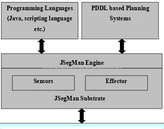
Figure 2: Architecture of JSegMan
JSegMan is a perceptual substrate that uses computational vision to "see" the Microsoft
Windows graphical direct-manipulation interface. JSegMan enables other programs to be
able to see the graphical interface screen as a human would see it. This enables programs
to interact with Microsoft Windows as if it were a user sitting at the console instead of
relying on low-level APIs. With JSegMan we can create and test more realistic cognitive
models of direct-manipulation interface usage, build AI agents that can reason about and
use the graphical interface, and write scripts and programs that learn and perform routine
tasks in the graphical interface.
JSegMan is a substrate because it is a layer of functionality that sits just above the level
Sensors Effector
JSegMan Substrate Programming Languages
(Java, scripting language etc.)
PDDL based Planning Systems
JSegMan Engine
perceive and manipulate the graphical user interface. JSegMan itself does not perform
any functionality except segmenting the screen into well-understood features and widgets
that other programs and scripts can utilize for their own ends.
The computational vision routines that JSegMan use are fairly rudimentary -- coming no
where close to the sophistication of human vision. However, the Microsoft Windows
graphical user interface is highly rectilinear and highly standardized so we can use short
cuts for detecting features and widgets on the screen. This chapter goes into more detail
on how JSegMan segments the screen into useful visual components.
The architecture is a layered architecture. On the bottommost level lies the operating
system. For the current version of JSegMan, the only operating system completely
supported is Microsoft Windows; JSegMan feature detection routines are geared
specifically for recognizing screen widgets that are defined by the Microsoft Windows
look-and-feel. However the substrate has been tested to work with KDE and GNOME
desktop environment with a minimal support of widgets on these desktops - just enough
to demonstrate JSegMan in action.
JSegMan sensor and effector subsystems
There are two main sub systems that make up the JSegMan system. These are the sensor
The effector subsystem of the JSegMan system manages all interaction with the computer
as a human would. It allows for various mouse operations like moving mouse pointer,
single click, double click and pressing of specific keys on the keyboard. This sub system
of JSegMan also allows for saving all the events being executed on the system to a text
file and later plays all the events from a text file. The implementation of effector
subsystem is quite simple compared to the sensor subsystem, since basic functionality of
moving mouse and typing key-strokes is available through Java API’s. The effector
subsystem builds on top of these basic Java API’s providing incremental movement of
mouse pointer and typing of sentences instead of single characters.
The sensor subsystem of JSegMan deals with low-level details of the screen processing.
It allows for image captures of the screen, identifying color attributes of screen pixels at
the screen level for image processing. This subsystem also does all the identification of
objects on the screen including windows, buttons and text among others. On completing
the processing of the screen once, JSegMan systems stores information about the widgets
and text identified on the screen in its internal database, which can be queried by any
other system using JSegMan as a library to query the widgets and fonts available on the
screen. This information is stored as a part of JSegMan engine.
Object recognition and optical character recognition is a complex subject that has
received attention over the past 30 years. In spite of many years of research, tools that can
associated with the ambiguity in distinction of objects and recognition of similar looking
objects in a variety of contexts.
The task of object recognition can be broadly separated into two categories: the
recognition of machine related data which are uniform in size, shape and include
computer fonts, windows and buttons among other widgets. In contrast, real world
objects or hand written characters are non-uniform; they can be perceived from a variety
of different angles and can be produced in different shapes, yet be identifiable by the
human eye.
The JSegMan sensor subsystem uses simple vision computation algorithms to identify the
screen pixels and aggregate the information of each pixel to recognize the text and
widgets on the screen. The sensor subsystem of JSegMan processes the pixel level
details from the screen captured image and creates pixel groups [30]. These pixel groups
are then identified for specific properties that various shapes related to a desktop
environment have. On establishing relations between these pixel groups, we have high
level vision of the desktop environment in terms of text and widgets available on the
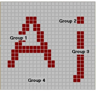
Figure 3: Zoomed image of characters ‘A’ and ‘j’ showing different groups in the image
After obtaining a screenshot of the desktop environment, the JSegMan sensor subsystem
groups a set of pixels of the same intensity adjoining each other. Figure 3 shows the grouping of pixels for characters "Aj". Group 1 is a pixel group comprised of pixels in
letter 'A'. Group 2 and 3 combined together represent the pixels of character 'j'. Group 4
is the pixel-group for background pixels.
Once pixel groups are identified, they are examined for specific shapes and for
relationships between shapes. This is where it is identified that group 2 and 3 shown in
group of pixels, one either needs to examine the arrangement of pixels within the group,
or one could look at pixel-neighbor numbers.
Each group has an array of neighbor numbers associated with it. The
pixel-neighbor numbers are encoding of the relationships between pixels within the group.
Each pixel in a group has 0-8 neighbors. Looking at an individual pixel in a pixel-group,
there are eight possible positions that a neighbor can be in: west, southwest, south,
southeast, east, northeast, north, and northwest. We assign a numerical value to each
neighbor position, respectively. Thus the west position is assigned to "0" and the
northwest position is assigned to "7".
Figure 4 (a) Figure 4 (b)
Each of these numbers corresponds to a bit in a single integer. Thus if a pixel is the
top-right corner of a box, it has neighbors to the south (position 2), southeast (position 3), and
to the east (position 4). The pixel-neighbor value of that top-right corner pixel is 2^2 +
2^3 +2^4 = 28.
For an entire pixel-group, we add up all the member pixels with pixel-neighbor values of
0, 1, 2, ..., 255. For example, a group representing a 5-by-5 solid box, the
For an entire pixel-group, we add up all the member pixels with pixel-neighbor values of
0, 1, 2, ..., 255. For example, a group representing a 5-by-5 solid box, the
pixel-neighbor numbers will look like:
pixel_neighbors[0] = 0 pixel_neighbors[1] = 0 pixel_neighbors[2] = 0 pixel_neighbors[3] = 0 pixel_neighbors[4] = 0 pixel_neighbors[5] = 0 pixel_neighbors[6] = 0 pixel_neighbors[7] = 1 ....
pixel_neighbors[28] = 1 pixel_neighbors[29] = 0 pixel_neighbors[30] = 0 pixel_neighbors[31] = 3 ....
pixel_neighbors[112] = 1 ....
pixel_neighbors[124] = 3 ....
pixel_neighbors[193] = 1 ....
pixel_neighbors[199] = 3 ....
pixel_neighbors[241] = 3 ....
pixel_neighbors[255] = 9
The four corner pixels generate unique pixel-neighbor values (7, 28, 112, 193). There are
three pixels on each edge if you exclude the corners (31, 124, 199, 241). There are nine
pixels in the center that are completely surrounded by neighbors' (255).
We can detect a single-colored box by looking for pixel-groups with the following
combination of pixel-neighbor numbers:
pixel_neighbors[7] == 1 AND
pixel_neighbors[28] == 1 AND
pixel_neighbors[112] == 1 AND
pixel_neighbors[193] == 1 AND
pixel_neighbors[31] > 1 AND
pixel_neighbors[124] > 1 AND
pixel_neighbors[199] > 1 AND
pixel_neighbors[241] > 1
Listing 6: Pixel neighbor numbers that uniquely identify the solid 5-by-5 box
Conjunctive tests such as the one described above for finding a box were used in the
original C++ code for SegMan and were then ported to the Lisp side for flexibility.
Eventually we developed a declarative form in which pixel patterns could be specified.
The form allows not only neighboring values to be specified, but also other properties of
1. count is the number of pixels in the group;
2. size is the area of the group's bounding box;
3. area (poor naming, for historical reasons) is the ratio of count to size;
4. height is the height of the group's bounding box;
5. width is the width of the group's bounding box;
6. red is a component of the group's RGB value;
7. green is a component of the group's RGB value;
8. blue is a component of the group's RGB value;
9. color is the group's numerical RGB value.
We define patterns to capture combinations of group properties. The group properties are
accessible to an application through JSegMan substrate API's described later in this
chapter.
Simple segmentation of the screen into pixel-groups gives us a lot of power in terms of
recognizing features. However, simple segmentation only allows us to see shapes that
consist of a single pixel-group. Often it is valuable to recognize features on the screen
that are made up of more than one pixel-group. Examples of features made up of multiple
pixel groups are icons, buttons, window borders, and strings of letters.
To recognize features that are not made up of a single pixel-group we must employ a
do this by looking for specific pixel-groups that might be part of overall feature. We do
this by selecting pixel-groups that have the right shape (the correct pixel-neighbor
numbers). Not all pixel-groups with the correct shape are necessarily going to be part of
the feature we are trying to detect. The second step is to choose from the candidate
pixel-groups the ones that are in proximity to each other and in the correct spatial configuration.
The SegMan system provides a variety of functions that find pixel-groups based on the
spatial relationship to others.
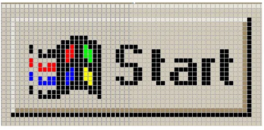
Figure 5: Windows “Start” button
For example, a standard Windows button is a rectilinear feature that appears to be raised
out of the screen. This raised effect is created by applying a thin strip of color around the
edges; lighter on the top and darker on the bottom. As far as JSegMan sensor subsystem
is concerned, a button is made up of two pixel-groups: the two L-shaped regions, with
rectangle enclosed inside these L-shapes that may contain other pixel groups. However,
these three groups must be in the correct relationship to each other in order to form what
looks like a button. The lighter L-shape (upper shading) must be directly above and to the
the right of the rectangle. When these relationships hold, there is a feature recognizable to
the human use as a button.
The following is pseudo code for recognizing a button:
PROCEDURE find_buttons (screen) DO
rectangles = find_all(rectangles, screen)
upper_shadings = find_all(upper_shading, screen) lower_shading = find_all(lower_shading, screen) buttons = EMPTY_LIST
FORALL rect IN rectangles DO
upshade = find_group_containing(rect, upper_shadings) lowshade = find_group_containing(rect, lower_shadings) IF distance_between(upshade, rect) < 5 AND
distance_between(lowshad, rect) < 5 AND
color(upshade) > color(lowshade) THEN DO append(rect, buttons)
RETURN buttons
Listing 7: Pseudo code to find all buttons on screen
In the first stage, we find all the pixel-groups of the shapes we need: rectangles,
upper-shading, and lower-shading. Buttons is an empty list into which we will collect all
features that look like buttons. In the first stage, we iterate through the rectangles, looking
for those in the proper relationship to the other shapes we have indicated. We find a
pixel-group in the upper_shadings list that most closely contains the rectangle. We find a
pixel-group in the lower_shadings list that most closely contains the rectangle.
ideally, will contain a rectangle if the feature is a button. The next check is proximity of
the L-shapes to the rectangle. This is very important because a button might be contained
in a window and L-shaped shaded areas also bound windows. But if the shading belonged
to a window, one or both shadings will probably be further than five pixels away. Finally,
we much make sure that the shape above the rectangle is lighter in color than the
L-shape below the rectangle. If the upper L-L-shape was darker than the lower L-L-shape,
perceptually, the feature will look recessed into the screen instead of raised.
All features that comprise of more than one pixel-group can be detected by applying one
or more of the following relationships: contains, above, below, to the left, to the right.
Additional details such as distance may be required to ensure robust recognition.
Description of system files and API's
The following discussion is what to find in each file that makes up the JSegMan system.
It discusses the various Java classes and the functionality of the public API's available in
each of the classes.
Pixel: This is a very basic class that stores information about a pixel on the screen. It
stores information about coordinates of this pixel, its color, the pixel group it belongs to,
pointer to next pixel in its group and its neighborhood number. It does not have any
public API's.
PixelGroup: This class contains information about a group of pixels. The following
• Absorb: This function takes a PixelGroup as an argument and merges it with
the current PixelGroup.
• AddPixel: Add a single pixel to the current PixelGroup.
• Area: Return ratio of number of pixels in the rectangular area contained by
the pixel group.
• Contains: Returns if a given PixelGroup is contained inside the current
PixelGroup.
• CountNeighbors: Calculates the neighbor number for the pixel group,
enabling it to be identified against known neighbor numbers.
• DistanceTo: Returns the shortest distance from this pixel group to another
pixel group. This function is sometimes useful in distinguishing widgets too;
for example the neighbor number for a window and button is computed to be
the same, but the distance of the edges and the central region helps in
distinguishing between a button and window.
• GetScreen: Takes a screenshot of current screen for processing.
• GrowGroup: Given a particular pixel coordinates, this function finds pixels in
its neighbor having the same intensity and adds it to current pixel group.
• Height: Determines the maximum vertical distance between two pixels of this
pixel group.
• IsToLeftOf: Determines if a given group is to left of the current pixel group.
• IsToRightOf: Determines if a given group is to right of the current pixel
• LeftDistanceTo: Determines distance from current pixel group to left edge of
another pixel group.
• Perimeter: Determines the perimeter of given pixel group
• RightDistanceTo: Determines distance from current pixel group to right edge
of another pixel group.
• SetColor: Allows to change the color intensity of a given pixel group in
internal representation of data structures in JSegMan. This API is useful
when we have colors in a widget that closely resemble each other, but are not
exactly the same in their intensity.
• ShowMe: This function shows a frame of current desktop image along with
the selected pixel group highlighted in the image.
• Width: Determines the maximum horizontal distance between two pixels of
this pixel group.
PixelGroupList: PixelGroupList class is useful for aggregating group of pixels, in order
to identify patterns. For example, in letter 'i', the dot at top at the step of 'i' are identified
as separate groups, however they are added to same pixel group list and this aggregate
representation is used for further reference to the letter 'i'.
• AddGroup: Add another pixel group to current pixel group list
• Contains: Determines if a given pixel group is part of current pixel group list.
• GetGroupAbove: Get pixel group above current pixel group list.
• GetGroupBelow: Get pixel group below current pixel group list.
• GetGroupToRight: Get pixel group to right current pixel group list.
• RemoveGroup: Remove a given pixel group from current pixel group list.
ScreenDifference: This class has just one public API. It takes two screenshots, or part of
screen and determines if there is any difference between the two images. This is
particularly useful to determine quickly if there has been any updates to the screen,
before performing the complete screen processing task.
ScreenManipulator: ScreenManipulator class forms the effector subsystem of JSegMan.
The following is a brief description of its public API's.
• DoubleClick: Performs a double click of left mouse button
• EndRecordEvents: Stops recording events being performed by effector
subsystem to a file.
• KeyDown: Presses a key on the keyboard, and the key is held down until
KeyUp, SingleClick or DoubleClick is called. This function can identify a
given key to be pressed either by the character to be pressed or it ASCII value.
• KeyUp: Releases a previously pressed key. This function can identify a given
key to be pressed either by the character to be pressed or it ASCII value.
• MouseDown: Presses the left mouse button and keeps it down until
MouseRelease is called.
• MouseRelease: Release a previously pressed left mouse button.
• MouseMoveTo: Incrementally moves the mouse from one pixel coordinates to
• PlayEventsFromFile: Reads events recorded into file and plays them on
current screen.
• PressKey: Press and release a key identified by character or its ASCII value.
• RecordEventsToFile: Begins recording of all events performed by JSegMan
effector to a file for playback at a later time.
• RightMousePress: Press and release the right mouse button, thus simulating a
single click.
• SingleClick: Performs a single click of right mouse button.
• WriteWord: An aggregate function of KeyPress that allows JSegMan effector
subsystem to press a set of characters one after another.
ScreenProcessor: This class provides most functionality for JSegMan sensor subsystem.
It helps in identifying pixel group patterns and storing them in an internal data structure.
Most of the functions described here are called internally to do most of the work, but are
also provided as public API. The following are the API's provided by this class.
• CountEightNeighbours: Performs a counting of neighbor pixels to determine
pixel neighbor number.
• FindBasicGeometry: This function triggers determining of various patterns in
on-screen widgets. It internally also calls other functions described below.
• FindButtons: Find all buttons and store them in its internal representation.
• FindCheckBoxAreas: Find all check boxes and store them in its internal
• FindHorizontalScrollbar: Find all horizontal scroll bars and store them in its
internal representation.
• FindListBoxes: Find all list boxes and store them in its internal representation.
• FindTextAreas: Find all text areas and store them in its internal representation.
• FindVerticalScrollBars: Find all vertical scroll bars and store them in its
internal representation.
• FindWord: Find a given work on screen and return its pixel coordinates.
• GetGroupsInside: Get a list of all groups contained inside a given pixel group.
• GetNeighborNum: Get the neighborhood number of a given pixel group.
• GetPixelPtr: Returns pointer to pixel at a given coordinate location.
• GetPixelPtrDown: Returns pointer to pixel below a given coordinate location.
• GetPixelPtrUp: Returns pointer to pixel above a given coordinate location.
• GetPixelPtrLeft: Returns pointer to pixel left of a given coordinate location.
• GetPixelPtrRight: Returns pointer to pixel right of a given coordinate location.
• GetPixelPtrUpLeft: Returns pointer to pixel above and to left of given
coordinate location.
• GetPixelPtrUpRight: Returns pointer to pixel above and to right of given
coordinate location.
• GetPixelPtrDownLeft: Returns pointer to pixel below and to left of given
coordinate location.
• GetPixelPtrDownRight: Returns pointer to pixel below and to right of given
• GetHeight: Get height of screen
• SetNeighborNum: Allows to set neighborhood number of a pixel group. This
value overrides the value computed by the system.
ScreenSource: This class allows for basic functions on the screen like capturing the
screen and providing limited information about the image captures. The following is a
description of API's made available by this class.
• CaptureScreen: Take screenshot of the entire or a part of the screen.
• GetR: Return R value of RGB given a particular pixel.
• GetG: Return G value of RGB given a particular pixel.
• GetB: Return B value of RGB given a particular pixel.
• GetHeight: Returns height of captured screen.
• GetWidth: Returns width of captured screen.
JSegMan as a programming environment
The JSegMan system provides complete access to the Windows user interface. As a
result of this, using JSegMan one can interact with the user interface without using any
Windows APIs.. This feature of JSegMan makes it attractive for running tests on new
programs.
Say a new product has to be tested. Traditionally, it would require someone to sit down
the expected outputs. All such tests are a series of giving inputs to the program and then
comparing the actual and expected outputs.
Now as we have a system that can identify the components of the user interface i.e.
sensors and also components that can act on the user interface i.e. effectors, we can build
programs using these sensors and effectors. Such programs can assume that they have all
the knowledge of the user interface including the windows, window titles, buttons, check
boxes, scroll bars, individual characters and characters grouped into words. Also its
possible to act on the user interface with functions that allow to press a series of keys i.e.
type a word, single click and double click mouse buttons.
All these functions provided by JSegMan serve as a base for a new set of programs to be
written over the JSegMan system.
In order to create a system where the user is completely independent from the low level
calls that interpret and manipulate the user interface, a JSegMan engine is used. The
JSegMan engine's job is the continuously scan the user interface and make relevant
information available to the user program(s). What we gain from this approach is that the
user part of the code does not have to worry explicitly about scanning the user interface
and do the processing. Instead, the user program will just focus on how it is going to use
the user interface. Another advantage of this approach is that, if there are multiple
programs who want to get information about the current state of the user interface, all of
identifying of screen objects. Instead they will get that information from the JSegMan
engine.
Similarly the actions like keystrokes and mouse button clicks are communicated to the
user interface through the common JSegMan engine.
The remaining part of the sub-section illustrates how a sample user code will use the
JSegMan engine. This is a simplistic demonstration of perceiving JSegMan as an engine.
The JSegMan engine stores its findings about the user interface in a file. The user
program finds out the information from this file. However, for performance reasons an
efficient data structure like a hash table would be a better choice.
In order to start using the JSegMan engine, it has to be invoked by hand. Once the
JSegMan engine is started, it continuously scans the user interface and put the
information it finds on user interface into the common data structure, in current case - a
file. The following user program will get the information from the engine by reading this
file.
The code presented here is in Java. This is a very simple demo, where this user program
simply moves the mouse cursor over the objects that are found by the JSegMan engine
one by one.
import java.awt.*;
public class EngineDemo {
public static void main(String[] args) throws Exception {
/* The following is opening the file, 'widgets.log' in which * the JSegMan engine stores its findings of the user interface * The engine stores the type of object (button, scrollbar etc.), * and its top-left and bottom-right (x, y) co-ordinates of the * objects founds.
*/
File fp = new File("./","widgets.log"); FileReader fs = new FileReader(fp);
BufferedReader reader = new BufferedReader(fs);
/* Make an instance of Robot object.
* This can even be moved to the JSegMan engine */
Robot bot = new Robot();
int delay = 0; int flag = 1;
String read = new String();
/* Let this user program run till there are no new objects */ while(flag == 1)
{
/* Read findings of the JSegMan engine from the common data structure */ read = reader.readLine();
if(read == null) {
flag = 0; /* If no new objects, set flag = 0 and exit */ System.exit(0);
}
System.out.println(st.nextToken()); while (st.hasMoreTokens()) {
String myString1 = st.nextToken();
int x = (int ) Integer.parseInt(myString1); String myString2 = st.nextToken();
int y = (int ) Integer.parseInt(myString2);
/* Move the mouse cursor to the objects found * by JSegMan engine one by one
*/
if(x < 1024 && x > 0 && y < 768 && y > 0) { bot.mouseMove(x, y); bot.delay(1000); } } } System.out.println("Program Complete"); System.exit(0); } }
Listing 8: Sample code to point to all objects on screen identified by JSegMan sensor subsystem
JSegMan interaction with PDDL based planners
The Planning Domain Definition language is intended to represent the "physics" of a
domain, in the sense it describes the current state of the domain, the actions possible in
the current state, to what state those actions would lead us to. For the JSegMan system,
PDDL is the glue between the JSegMan substrate and the planner. As most of the
planners support PDDL, describing the desktop domain in PDDL makes it possible for
any planner to be able to access the sensor/effector services provided by the JSegMan
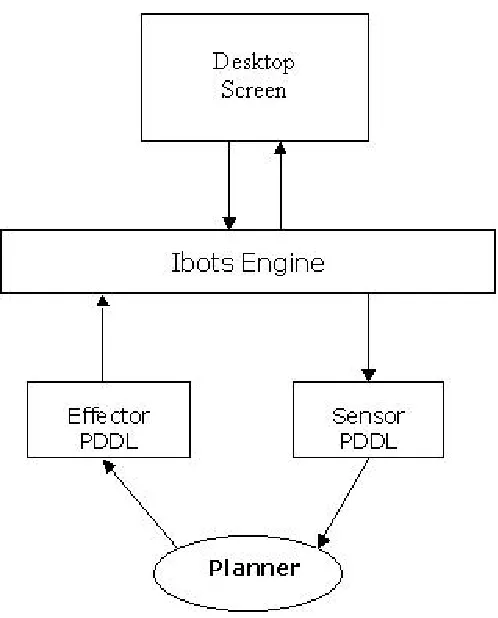
Figure 6: Architecture of interaction between user interface, JSegMan substrate and PDDL based
planner
Sensor PDDL: The sensor PDDL is a text based data file written by the JSegMan engine
and contains the current view of the desktop as output by the JSegMan engine. The
planner that is acting on the desktop will read the current state of the desktop from this
file. This includes the state of the windows, buttons, text boxes, radio buttons etc. in
terms of their positions (for windows, buttons, etc), their current state i.e. if they are
selected or not (for radio button, checkbox, listbox etc) and the possible states from there
and hence the information on the desktop domain can be easily communicated to the
planner.
The planner is expected to read the sensor PDDL file only once, initially. After that the
planner takes actions on the domain which are communicated to the system through the
effector PDDL. One interesting thing here is that the planner does not need to read the
current state of the domain again after doing actions on the domain. The planner will
update its view of the domain by merging the views from the initial PDDL file and
applying an incremental action it took on the domain. However one may consider
synchronizing the planner view of the domain and the current view of the domain to
avoid ambiguities that may occur between the action specified by the planner and the
thing acted upon by the effector.
Listing 9 describes the domain 'desktop' with a Window defined as an object in the
'desktop' domain:
(define (domain desktop)
(:requirements :strips :equality :typing :conditional-effects) (:types location object)
(:constants (Window - object)) ...
Listing 9: Definition of existence of a Window object in PDDL
Listing 10 is a representation of PDDL, which describes an action on the Window object
- i.e. moving the Window from one location to the other. As one can see, it defines the
if and only if the specified pre-conditions are met. It then goes through the specified
parameters - here the locations and then performs the action. In case of JSegMan, the
planner will write out the action in Effector PDDL file as described in the next section.
The effector will then read commands from the Effector PDDL and do the corresponding
actions on the desktop resulting in the action actually being performed. At the same time
the planner will update its view of the domain based on the actions mentioned in the
effects: of the section.
(:action move-window
:parameters (?initial_position ?new_position - location) :precondition (and (at Window initial_position) (not (= ?initial_position ?new_position)))
:effect (at Window ?new_position)
Listing 10: PDDL action describing moving of a Window from one position to another
In the above example, we did not consider other objects included inside the Window, like
the buttons, scroll-bar, icons etc inside the window - which will move along with the
window.
We now see and example were we describe an action in which we drag in an icon object
into a window as if we want to copy the file represented by the icon as in Windows
Explorer.
(:action move-in-window
(in ?x)) )
Listing 11: PDDL action describing drag-and-drop behavior of dragging an icon into a window
As we can see that in above example the PDDL defines a precondition to check if the
Icon object and the Window are not the same thing - as it is not possible to move an
object into itself.
This is a fine example that shows that we have to be very ver careful in describing the
domains using PDDL and we need to describe the current states, preconditions and the
effects extensively else the planner may be conveyed incorrect information and hence
may come up with an infeasible plan.
We finally look at another action that takes out an object from the Window.
(:action move-out-window :parameters (?x - Icon)
:precondition (not (=?x Window)) :effect (not (in ?x))
Listing 12: : PDDL action describing drag-and-drop behavior of dragging an icon out of a window
This example is very similar to the PDDL that specified the action to put an Icon into a
Window.
Effector PDDL: The effector PDDL contains information to be communicated from the
planner to the JSegMan engine. Like the sensor PDDL, the effector PDDL is also a text
based data file in PDDL syntax.