A Multiagent System for Edge Detection and Continuity
Perception on Fish Otolith Images
Anne Guillaud
´
Ecole Nationale d’Ing´enieurs de Brest, Technopˆole Brest-Iroise, BP 30815, 29608 Brest Cedex, France Email: [email protected]
Herve Troadec
Institut Franc¸ais de Recherche pour l’Exploitation des Mers, Center de Brest, Laboratoire de Scl´erochronologie des Animaux Aquatiques, BP 70, 29280 Plouzan´e, France
Abdesslam Benzinou
´
Ecole Nationale d’Ing´enieurs de Brest, Technopˆole Brest-Iroise, BP 30815, 29608 Brest Cedex, France Email: [email protected]
Jean Le Bihan
´
Ecole Nationale d’Ing´enieurs de Brest, Technopˆole Brest-Iroise, BP 30815, 29608 Brest Cedex, France Email: jean.le [email protected]
Vincent Rodin
´
Ecole Nationale d’Ing´enieurs de Brest, Technopˆole Brest-Iroise, BP 30815, 29608 Brest Cedex, France Email: [email protected]
Received 5 July 2001 and in revised form 26 January 2002
We present an algorithm for fish otolith growth ring detection using a multiagent system. Up to now, the identification of growth rings, for age estimation, is routinely achieved by human readers, but this task is tedious and depends on the reader subjectivity. One of the major problems encountered during an automatic contour detection is the lack of ring continuity perception. We present an approach to improve this continuity perception based on a 2D reconstruction of rings using a multiagent system. The originality of the approach is to use local edge detection achieved by agents and combine it with continuity perception that active contours allow.
Keywords and phrases:edge detection, multiagent system, otolith.
1. INTRODUCTION
The growth of the otolith is an accretionary process. The otolith structure is made of alternative opaque and translu-cent contranslu-centric rings. The purpose of growth rings identifi-cation is to acquire data on age and growth of fish popula-tion. Such data are needed in a great number of biological and ecological studies and to improve stock management. Up to now, this analysis has been mainly limited to a ring count. Ring continuity is a major concept on which readers base their ring detection.
This paper presents an approach to this continuity per-ception based on the 2D reconstruction of rings.
In 1996 Rodin et al. [1] tried to reconstruct the rings in
the nucleus, which is the otolith growth starting point. As the shape of the ring is forced to be similar to the external con-tour, drifting of this shape points is thus avoided. Neverthe-less, the rings shape can only be approximately determined using this method. Therefore, the last rings that are very thin and only distinct around the main growth axis (Figure 1) are not well detected.
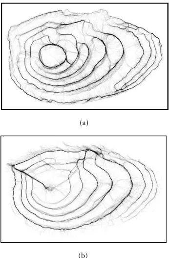
Another type of methods has recently been set for detect-ing features in images, which are based on multiagent sys-tems [5, 6, 7, 8, 9]. Multiagent syssys-tems foundations can be found in different research themes, such as distributed arti-ficial intelligence or artiarti-ficial life [10]. An agent is an entity which can be virtually or physically embodied, evolving in an environment which can contain other agents. Agents are generally autonomous, which means that they do not need external intervention to act according to the data that they perceive [11]. A multiagent system is composed of an en-vironment, passive objects situated in this enen-vironment, at least two agents which can act on these objects, and relations between all entities of the system. These agents achieve quite simple actions, but by sharing their results, their work can bring to a more complex process. In [9] autonomous agents were used to detect homogeneous regions in brain scan im-ages. Each agent can achieve tests on pixels around it in a cir-cular neighborhood, as computing the variance or the mean gray level. If it finds that its neighborhood satisfies the con-ditions to be a region, the central pixel will be marked and new agents will be generated to grow the region. If the agent does not recognize a region, it will move to another place. This method is well adapted for brain scan images, because of regions characteristics regularity for tumors, sane parts, and so forth. In [8], a multiagent system is used to segment cytological images. One type of agent is defined that could be adapted to the research of four different features in cytolog-ical images, as the nucleus or the background. The discrim-ination is also mainly based on the regions characteristics. On the opposite, if we consider that otolith images can be divided in two types of regions: dark rings and light rings, it will be almost impossible to find some statistical charac-teristics that would always fit to each type of region. For ex-ample, as the mean gray level increases from the nucleus to the edge, the mean value of a dark ring near the edge can be superior to the mean value of a light ring near the nu-cleus (Figure 1). In [6], a multiagent system is proposed to detect concentric rings that can be found in natural objects such as tree trunks. Each agent can move around in its envi-ronment which is a grayscale image; its two square-shaped sensors on the pixels of the image allow it to follow light rings (light agents) or dark rings (dark agents) by moving in the direction of the lighter pixels for light agents (resp., darker pixels for dark agents). If the agents have gone over a loop, they can validate their path as a ring. The advantage of this method is to detect very quickly circular structures (a few seconds). This property is interesting for an appli-cation on otolith images featuring concentric rings. Never-theless, on such images agents encounter problems to find all loops for old individuals, with very thin and poor con-trasted rings (Figure 1). This difficulty was also observed
Figure1: Rings detected by free agents on an eight-year-old indi-vidual.
with other methods dedicated to otoliths image processing [1, 2, 4].
To tackle this problem, we present in this paper an adap-tation of the multiagent system to otolith growth ring detec-tion, taking into account high level information (shape of the otolith edge and position of the growth center).
2. DESCRIPTION OF THE INITIAL MULTIAGENT SYSTEM
As explained above, the system is composed of reactive agents. Each agent has three sensors allowing it to get in-formation about its environment (Figure 2). One unit sen-sor (one pixel) allows it to locate itself on the image. Two unit sensors are located in front of the agent and distant one from the other. The angle formed between these two sensors equalsθ. They return the grayscale levels on the part of the image where they are located.
A dark agent tries to move where the values returned by the sensors are minimal. A white agent does the opposite. The agents deviation is proportional to the gray level diff er-ence between the two sensors. The following equation ex-plains how an agent computes its orientation at step t de-pending on its orientation at stept−1 and on the difference of intensity between its two sensors:
δagent(t)=δagent(t−1) +
I1−I2
P , (1)
and can be adapted to the lengthLof the sensors,I1(resp., I2) is the intensity read by the sensor 1 (resp., 2). The tuning of parameterPis explained in [12]. Depending on the data obtained with its sensors and on its internal states, each agent takes decisions. Those internal states are represented by a fi-nite state machine. At the beginning the agent is initialized at random on the image and at the end it can validate a ring if it has gone over a loop or dies if it has not found any ring, after a certain time. The number of agents has been set to five for this particular application. A more important number of agents would not improve much results, as interactions be-tween agents are limited. When an agent dies (if it is too old or if it has found a ring), a new agent is initialized randomly on the image.
Although this detection method is very quick, problems appear when rings are discontinuous, so that agents cannot cover the whole ring to come back to their initial position (Figure 1). Only distinct rings are easily detected. Neverthe-less, agents may have detected an important part of the ring. We will call agents using this behaviorfree agents.
We present a new way to exploit the behavior of agents using an a priori knowledge about otolith growth.
3. USE OF HIGH LEVEL INFORMATION
As other calcified structures (scales, fin rays, vertebrae), the otolith is composed of concentric rings which appear each year. Therefore, the shape of the rings is quite parallel to the global shape of the otolith (Figure 1). Otolith growth starts from its center, which is called nucleus. By comparing the direction of the agent turning around this nucleus to the di-rection of the contour of the otolith, a decision is taken to recognize whether its path is correct or not.
Some previous steps are necessary to record information concerning the shape of the otolith and the position of its nucleus, and are described below.
3.1. Preliminary steps
(a) The contour of the otolith is detected and its coordi-nates are recorded.
(b) Agents with sensors on the image pixels (Ballet et al. [6]) try to detect concentric rings and the coordinates of the smallest one are recorded.
(c) The nucleus is searched inside the smallest ring. The first white ring is usually well contrasted and easily val-idated by agents. Then we can search the minimum gray level point in a little neighborhood around the middle of the ring, which corresponds to the nucleus (Figure 3).
(d) Knowing the position of the nucleus and the coordi-nates of points constituting the contour of the otolith, the orientation of little segments composing the con-tour is computed all around the otolith and this infor-mation is recorded on a single image. Thus, this im-age is divided in sectors going from the nucleus to two close points of the contour. In every sector the local orientation of the contour is inscribed (Figure 4).
Figure3: First ring and nucleus detection.
Figure4: Image of local orientations.
I2
I1
Figure5: Agent sensors on the gray level image.
When this image is created, the agents will have to detect growth rings using these high level knowledge. We propose two different methods to reach this goal:Directed agentsand Reconstructed path.
3.2. Directed agents
In this approach, agents direction is in the same time influ-enced by local gray levels and by the orientation of the ex-ternal otolith edge. The following equation explains how an agent computes its local orientationδat steptdepending on its orientation at stept−1, and on the gray levels of its two sensors (Figure 5):
δlocal(t)=δagent(t−1) +I1−I2
P . (2)
I3
Figure6: Sensor of the same agent on the orientation image.
Figure7: Image of the localization divided in two areas for old in-dividuals; size of the agents sensors in each case.
level on the orientation image:
δcontour=2π× I3
255. (3)
The final agent orientation will be computed using both local and high level orientation, as explained in
δagent(t)=δlocal(t) +αδcontour−δlocal(t)
. (4)
In this equationαis a coefficient which varies from 0 near the nucleus to 1 near the external edge. This point expresses the growth of otolith from the nucleus to the edge: the shape of last rings is closer to the contour than the shape of first rings. Thus the shape constraint gets stronger when an agents move in the direction of the external edge. In Section 3.4, we ex-plain howαcan be computed using an image of localization (Figure 7).
Rings are validated when agents have gone over a loop and find again their initial position.
3.3. Reconstructed path
In this approach, agents are also aware of the external con-tour’s orientation, but their direction depends only on the gray levels of the otolith image. Agents record their path in an image by increasing the gray level of a pixel each time they go on it (Figure 8). At the end of the processing, this image will be thresholded to keep the most frequented paths. During the processing, the agents also record their path in another image, whenever their local orientation is similar to the one of the external contour (they know this orientation
(a)
(b)
Figure8: (a) Light agents path (on Figure 3), (b) dark agents paths.
Figure9: Most frequented and best oriented agents paths.
using the image created in step (d) of Section 3.1). A logi-cal AND between this image and the thresholded path im-age will allow to obtain a map of growth rings edges, which correspond to the most frequented and best oriented agents paths (Figure 9). This map will be used to begin rings recon-struction, starting from the smallest one around the nucleus, and using a method similar to active contours. The shape of the current ring is inflated, by translating each point of the shape using a vector, whose direction is similar to the one of a line going through the nucleus and this point (Figure 10). Growth stops when the correspondence between the inflated shape and the pixels of the edge map is maximal. This corre-spondence is computed by counting the number of common nonzero pixels between the inflated shape and the edge map (Figure 9).
By counting the number of rings detected with the first or the second method, the age of the fish can be estimated.
Figure10: Inflation of the current ring for next ring detection.
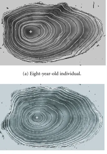
(a) Eight-year-old individual.
(b) Ten-year-old individual.
Figure11: Rings detected with reconstructed path method.
3.4. Agents parameters adjustment
The width of rings appearing during the fish growth de-creases when the fish gets older. Therefore, the size of agents sensors needs to be adapted in order to detect large rings near the nucleus and thin rings near the edge. Rings width can be approximated according to their position in the otolith using a growth model, but variability is very important between individuals. Nevertheless, the size of the otolith allows to es-timate roughly the number and the width of rings. Knowing the position of the nucleus and the coordinates of the otolith edge, it is possible to create an image which will inform the agent about its relative position on the otolith (Figure 7). In this image the gray level increases from 0 on the nucleus to 255 at the otolith edge. The agents will be provided with one sensor on this image. As the gray level of this image increases from the nucleus to the edge, the intensity read by the sen-sor will allow the agent to locate itself in the image. As it was
0 5 10 15 20 25 30
Nu
m
b
er
o
f
im
ag
es
0 3 6 9 12 15 18 21 24 27 30 33 36 39 42 45 48 51 Distance in pixels
Figure 12: Distribution of the distance between the nucleus de-tected automatically and the nucleus dede-tected by a human reader.
shown in [12, 13], agents can detect edges of different widths with the same parameters. Thus when otoliths are young, which means that rings width is quite constant, agents can detect all rings with only one set of parameters, but for older individuals they have to reduce the length of their sensors to improve thin rings detection, which appear at the end of the fish life. When the size of the main growth axis corresponds to an old individual, the image of the localization (Figure 7) will be divided in two sectors. The contour of the central area is defined by the points of the external shape reduced by an homothety with a factor of 3/4. These points are also defined by the pixels having the same gray levelGmaxin this image. According to the gray levelGan agent reads in this image, the lengthLof its sensors will be determined as ifG < Gmaxthen L=LmaxelseL=Lmin.
For our tests with plaice otolith images, the optimal val-ues forLmaxandLminwere, respectively, 8 and 2 pixels.
The localization image also allows to compute the coeffi -cientαdescribed in Section 3.2, asα=G/255.
4. RESULTS AND DISCUSSION
4.1. Automatic nucleus detection
The nucleus detection method has been tested by compar-ing the position of the nucleus automatically detected to the one of the nucleus detected by a human expert on a sam-ple of 119 plaice otolith images. As the real position of the nucleus is unknown, we can only measure the distance be-tween these two estimations to evaluate the method. We ob-tain a quite good detection of the nucleus with a 7.86 pix-els mean distance between automatic and manual detection, with a 512×512 resolution (Figure 12). The images for which the detection error is quite important are very bad contrasted and the first ring is very difficult to distinguish.
4.2. Age estimation methods
Figure13: Rings detected by directed agents.
0 10 20 30 40 50 60 70 80 90 100
%
1 2 3 4 5 6 7 8
Age group
Figure14: Percentage of good age estimation for directed agents on otoliths from age group 1 to 8.
processing. They only try to validate loops by searching for local intensity extremes. Therefore the bad contrasted or in-distinct rings are not detected.
As agents are aware of the shape of the otolith, in the di-rected agents method, they can go forward in areas where contrast between light and dark rings is very bad. The num-ber of detected rings has been improved with this method and fanciful loops, that can be detected by free agents, have been avoided (Figure 13). This method is nevertheless caus-ing a frequent under-estimation of the age of old fishes, be-cause the condition required to validate a ring—when an agent finds again its initial position—is not easily satisfied when rings are distinct only in a restricted area of the image (Figures 13 and 14).
The reconstructed path method allows to improve the detection of these last rings, using the local detection of edges achieved by agents, and guiding the reconstruction of a ring using the shape of the previous one. The percentage of good age estimation is thus better for old individuals (Figures 11 and 15).
The methods proposed in this paper give better results than those obtained with a mono-dimensional method ap-plied on otolith images, which is described in [14]. This method consists in searching intensity extremes on an image profile starting from the nucleus to the otolith edge. There-fore the structures continuity is not taken into account.
The reconstructed path method also presents better re-sults than those presented in [4] (deformable templates), mainly for old individuals because the shape of rings is more correctly detected. Otherwise, the graph method [1] gives
0 20 40 60 80 100
%
1 2 3 4 5 6 7 8
Age group
Figure15: Percentage of good age estimation for the reconstructed path on the same images.
Figure16: Result of the reconstructed path method on a pout fish otolith image.
similar results with those of the reconstructed path, but the latest is less time-consuming (2 minutes maximum against 12 minutes maximum). Moreover the graph method, which requires a polar transformation of the image using the nu-cleus as the center, cannot be applied to otoliths having several nuclei. Figure 16 illustrates the fact that the recon-structed path method can be used for processing more com-plex images such as pout fish otolith images. In this image, the otolith has actually three nuclei, but agents are still able to detect the first white ring. Then the center of this ring is searched; even if it is not meaningful, it is helpful to start ring reconstruction.
4.3. Discussion
Table1: Performance of different age estimation methods.
N=110 1D method Template method Graph method Directed Agents Reconstructed Path
1 to 3 y R=50 R=100 R=90 R=81 R=87
R: percentage of good age estimation AM: maximal error amplitude
otolith edge reduced by an homothetic transform centered on the nucleus, in order to search the position of growth rings [4]. Their position is determined by minimizing an energy function which is computed with the gray levels of the image. This method can only give an approximate shape to rings and presents quite low results for age groups from 5 to 8, in comparison with the reconstructed path method.
The graph method uses a polar coordinates transform to extract radials starting from the nucleus and going to the edge in the original image to display them one under the other in the final image [1]. Peaks, corresponding to light rings and valleys corresponding to dark rings are then ex-tracted using morphological transforms. Objects are then la-belled and closest objects are connected to reconstruct rings. This method gives results similar to the reconstructed path method, but cannot be applied to otoliths having several nu-clei because of the polar coordinates transform (Figure 16).
The deformable model method presented in [2], inspired by [15], cannot be easily compared with the methods we pro-pose because it has not been evaluated on a sample of test images.
However, this method may encounter problems to detect thin rings which are visible around the main growth axis for old individuals, as the energy function computed to inflate the model uses gray levels all around the otolith.
Processing time for estimating age with directed agents and reconstructed path on otolith images may be longer than the time necessary for a human person to estimate age. Nev-ertheless, a human person is not able to draw precisely by hand the position of the rings, or this would be a very long and tedious task. Moreover, the same person, at different times, or two different people, can make different estimations for the same image.
Ring detection on otolith images is a very complex prob-lem, as the number and the shape of structures to detect in an image is a priori unknown. Thus it is essential to use high level knowledge to improve this detection. For this reason it may be difficult to compare the methods we propose in this paper with more general methods presented in the lit-erature. However, agents present the advantage to perceive locally roof edges and structures continuity at the same time. Agents can also cooperate by sharing their work on the same
image. The use of snake curves thrown on the image instead of agents could be suggested. Nevertheless, snakes detect step edges, and in our application detection of peaks and valleys is more appropriate to localize growth rings. Moreover if agents are initialized on the image in an area where no ring is visible, they are able to move from this area, which would be more difficult for a snake, if its energy function does not allow it to evolve.
5. CONCLUSION
We have developed a method to perceive continuity of con-tours in textured, noisy, and low contrast images. Previous methods needed operator intervention to give the nucleus position whereas the pointing is automated here. The agents are able to detect local edges in the image, while perceiving their continuity by the way they move. This property is very interesting for processing otolith images, which are noisy and textured. Because they are too sensible to noise and texture, classical edge detection operators cannot be used with such images. Agents can also adapt locally the size of their sensors according to the ring width.
In the future we intend to find a new criterion for the agents to validate a ring, which should be more robust than the fact that the agents have to find again their initial posi-tion.
Plaice otolith images were used to develop automatic age estimation methods as they are quite simple compared to other species. Nevertheless, we hope to be able to adapt the method to more complex species (Figure 16), which can have several nuclei and less regular shapes.
REFERENCES
[1] V. Rodin, H. Troadec, H. de Pontual, A. Benzinou, J. Tisseau, and J. Le Bihan, “Growth ring detection on fish otoliths by a graph construction,” inProc. IEEE International Conference on Image Processing, vol. II, pp. 685–688, Lausanne, Switzerland, September 1996.
[3] A. L. Yuille and P. W. Hallinan, “Deformable templates,” in Active Vision, A. Blake and A. L. Yuille, Eds., Artificial Intel-ligence Series, chapter 2, pp. 21–38, MIT Press, Cambridge, Mass, USA, 1992.
[4] H. Troadec, A. Benzinou, V. Rodin, and J. Le Bihan, “Use of deformable templates for otolith 2D growth ring detection by digital image processing: application to plaice (Pleuronectes platessa) otoliths,”Fisheries Research Journal, vol. 46, no. 1-3, pp. 155–163, 2000.
[5] P. Ballet, V. Rodin, and J. Tisseau, “Edge detection using a multiagent system,” inProc. 10th Scandinavian Conference on Image Analysis, vol. II, pp. 621–626, Lappeenranta, Finland, June 1997.
[6] P. Ballet, V. Rodin, and J. Tisseau, “A multiagent system for detecting concentric strias,” inApplications of Digital Image Processing XX, vol. 3164 ofProceedings of SPIE, pp. 659–666, San Diego, Calif, USA, 30 July–1 August 1997.
[7] O. Boissier and Y. Demazeau, “ASIC: An architecture for social and individual control and its application to com-puter vision,” inProc. 6th European Workshop on Modelling Autonomous Agents in a Multi-Agent World, pp. 107–108, Odense, Denmark, August 1994.
[8] A. Boucher and C. Garbay, “A multi-agent system to segment living cells,” inProc. 13th IAPR International Conference on Pattern Recognition, vol. III, pp. 558–562, IEE Computer So-ciety Press, Vienna, Austria, August 1996.
[9] J. Liu, “Reactive agents for adaptative image analysis,” inProc. 2nd International Conference on Autonomous Agents, pp. 441– 448, Minneapolis, Minn, USA, May 1998.
[10] J. Ferber,Les syst`emes multi-agents: vers une intelligence collec-tive, InterEditions, Paris, France, 1995.
[11] P. Maes, “Modeling adaptative autonomous agents,”Artificial Life Journal, vol. 1, pp. 135–162, 1994.
[12] A. Guillaud, A. Benzinou, H. Troadec, V. Rodin, and J. Le Bi-han, “Parameterization of a multi-agent system for roof edge detection: An application to growth ring detection on fish otoliths,” inSPIE Electronic Imaging: Science and Technology, San Jose, Calif, USA, January 2000.
[13] A. Guillaud, Un syst`eme multi-agents pour la reconnaissance de formes sur des pi`eces calcifi´ees, Aide `a l’estimation de l’ˆage de poissons et de c´ephalopodes, Th`ese de Doctorat, Universit´e de Bretagne Occidentale, Brest, France, December 2000. [14] H. C. Welleman and F. Storbeck, “Automatic ageing of plaice
otoliths by means of image analysis,” inRecent Developments in Fish Otoliths Research, D. H. Secor, J. M. Dean, and S. E. Campana, Eds., pp. 271–282, 1995.
[15] L. D. Cohen, “On active contour models and balloons,” Com-puter Vision, Graphics and Image Processing: Image Under-standing, vol. 53, no. 2, pp. 211–218, 1991.
Anne Guillaudwas born in 1974. She has studied and taught at the ´Ecole Nationale d’Ing´enieurs de Brest (France). She received in 2000 the Ph.D. degree in signal and image processing.
Herve Troadecwas a researcher at the Ifremer institute (France). He was specialized in schlerochronology, which is a technique sisting in reading age of fishes for fisheries assessment. He con-tributed to the development of a software used for processing nu-merical images of calcified structures. This software is used in sev-eral laboratories in Europe and Africa. His last mission consisted in an expertizing mission in Morocco for the COPEMED project of the FAO (Food and Agriculture Organization), in august 2001. He died at 41 years old in an air crash in Malaga (Spain) on the 29th of August 2001.
Abdesslam Benzinou was born, on De-cember 7, 1970, in Casablanca, Morocco. He received the Ing´enieur degree in elec-tronics and software engineering from the ´Ecole Nationale d’Ing´enieurs de Brest and the Dipl ˆome d’ ´Etudes Approfondies (DEA) in electronics and optronics, with honours, from the Universit´e de Bretagne Occiden-tale, both in 1995 in Brest, France. He re-ceived the Ph.D. degree in January 2000,
from the same university, for his work dealing with the problem of designing and realizing of a computer vision system for the recog-nition of patterns on calcified structures (otoliths and statoliths). In September 2000, he was engaged as a Researcher in signal process-ing for metrology and communication systems at Schlumberger-RMS, Chasseneuil, France. In September 2001, he joined the RESO Laboratory at the ´Ecole Nationale d’Ing´enieurs de Brest, Brest, France, as a Maˆıtre de Conf´erences. Apart from teaching, his main fields of interest include signal analysis, computer vision, pattern recognition, and related aspects of mathematical modelling and optimization.
Jean Le Bihan was born in France. He studied at the ´Ecole Normale Sup´erieure, Cachan, and at the Universities of Orsay and Paris, and received the Agr´egation of applied physics. Then he became an Assis-tant Professor of electronic engineering at Brest University and received the degree of Docteur d’ ´Etat `es Sciences Physiques. From 1986 to 1988, he worked as a Visiting Re-searcher, first at Thomson, Orsay, then at
CNET, Lannion. Since 1988, as a Professor at the ´Ecole Nationale d’Ing´enieurs de Brest, he has been at the head of RESO Laboratory, working mainly in the area of optical communication systems and image processing.