On Some Design Issues of Space-Time Coded
Multi-Antenna Systems
Hsuan-Jung Su
Bell Laboratories, Lucent Technologies, Holmdel, NJ 07733, USA Email: [email protected]
Evaggelos Geraniotis
Department of Electrical and Computer Engineering, University of Maryland at College Park, College Park, MD 20742, USA
Email: [email protected]
Received 30 May 2001 and in revised form 30 January 2002
This paper concerns some design issues and tradeoffs of communication systems equipped with multiple transmit and receive antennas. The general space-time coding/modulation structure by Tarokh et al. (1999) is considered. Several design issues are investigated for this structure. The layered space-time architecture by Foschini (1996) is revisited as a special case of the general structure. It is also used to demonstrate the design and complexity tradeoffs of the system. Through intuitive and analytical explanations, as well as simulations, the design considerations for these space-time transmission structures and their contributions to the performance are shown.
Keywords and phrases:space-time codes, array processing, iterative processing.
1. INTRODUCTION
The growing demand of high data rate service has inspired studies on multi-antenna wireless communication systems in recent years (e.g., [1, 2, 3, 4, 5, 6, 7, 8, 9, 10, 11, 12]). From an information theoretic point of view, multiple antennas can increase the capacity of wireless channels [3, 4]. In practice, this increased capacity amounts to improved error perfor-mance when the communication data rate is fixed.
When there are not enough antennas at the receiver to resolve the transmission signal spaces, joint detection of the signals transmitted from different antennas may be necessary at the receiver. In this scenario, proper coordination of the signals transmitted on different antennas can help improv-ing the performance without additional cost. The space-time coding techniques in [8, 9, 10, 11], which integrate channel coding, modulation and antenna diversity to allow simulta-neous exploitation of coding gain (temporal diversity) and antenna diversity, are examples in this category. The draw-back of such signal coordination is intractable joint detec-tion complexity when the number of transmit antennas is large, unless certain throughput-inefficient signal coordina-tions are introduced [11].
If the number of receive antennas is large enough to re-solve the transmission signal spaces, the signals from
individ-ual transmit antennas can be detected separately after proper signal space separation. Signal coordination is not necessary in this case, and the throughput can be kept high. The lay-ered space-time (LST) architecture in [2] is an attempt to realizing the information theoretic result in [3, 4], namely, the multi-antenna channel capacity grows linearly with the smaller of the number of transmit antennas and the number of receive antennas. The LST uses one-dimensional signal per data layer. Its focus is more on the signal space separation at the receiver. While the channel coding method is, contrary to the space-time coding techniques, conventional.
In order to attain a compromise between throughput and performance when the receiver has a certain number of an-tennas, the authors of [8] later on extended their work to consider grouped space-time transmission (GST) [1]. In this system, the space-time coding advantages are explored by the antennas within the same group, while the system through-put can be kept high by transmitting the groups indepen-dently. As in the LST, signal processing at the receiver is re-quired in order to separate the signal groups. A zero-forcing method was employed in [1] for signal space separation.
being a special case which has one antenna per group. In this paper, we investigate the system properties and design issues of this general structure. Some design considerations and tradeoffs are revealed through intuitive, as well as an-alytical discussions. The issues discussed are then verified with simulations. Note that the issues considered in this paper pertain to an “open-loop” system, meaning there is no channel information feedback from the receiver to the transmitter.
This paper is organized as follows. In Section 2, the sys-tem model of the GST is given. We then discuss the antenna array processing issues in Section 3, which is followed by the power allocation issue in Section 4. In Section 5, spatial in-terleaving is discussed in the context of diversity advantage. Section 6 revisits the LST in terms of diversity and coding gain. In Section 7, we describe the application of the itera-tive minimum-mean-squared-error (MMSE) multiuser de-tection algorithm [13, 14] to the GST. Section 8 then verifies and concludes the design issues discussed with comprehen-sive simulation results. Finally, some concluding remarks are given in Section 9.
2. SYSTEM MODEL
In the remainder of this paper, the superscripts ∗, T, and
H are used to denote complex conjugate, matrix transposi-tion, and Hermitian transpositransposi-tion, respectively. The commu-nication system considered consists of a transmitter which is equipped withnantennas and a receiver which hasm antnas. At the transmitter, data is encoded by the channel en-coder, the encoded symbols are then divided intonstreams which will be transmitted simultaneously usingndistinct an-tennas after modulation.
The signal at each receive antenna is a noisy superpo-sition of the n transmitted signals corrupted by the fad-ing channel which is assumed to be flat, Rayleigh, and spa-tially independent, meaning fading is statistically indepen-dent from one transmit-receive antenna pair to another. Following the convention of [1, 2], we assume that fading remains constant within a data frame and varies from one frame to another. This assumption amounts to the worst case situation where temporal diversity is not available, and can serve as an upper bound on the error probability. For this system, the signalrtj received by antenna j(1 ≤ j ≤ m) at timetis given by
rtj= n
i=1 αi, jcit
Ei+ηtj, (1)
whereiis the transmit antenna index,Ei is the symbol en-ergy of theith transmit antenna,ci
tis the symbol transmitted from antennaiat timet, andαi, j is the path gain from the
ith transmit antenna to the jth receive antenna. The noise
ηtj is assumed to be additive white Gaussian (AWGN) with varianceN0/2 for both real and imaginary components.
For notational simplicity, we redefineαi, j as the product of the channel gainαi, jand the symbol amplitude
Eiin (1).
This change in notation does not affect the zero-forcing array processing, while it allows more concise presentation of our alternative approach. With this new notation, we now rewrite (1) in the vector form
rt=Ωct+ηt, (2)
where
ct=
c1
t, c2t, . . . , cnt
T
,
rt=r1
t, rt2, . . . , rtm
T
,
ηt=
η1
t, ηt2, . . . , ηtm
T
,
Ω=
α1,1 α2,1 · · · αn,1 α1,2 α2,2 · · · αn,2
..
. ... . .. ...
α1,m α2,m · · · αn,m
.
(3)
In the GST, the data to be transmitted are divided into
qgroups, each space-time coded and transmitted with one group of antennas. The antenna groups are disjoint. The pur-pose of space-time coding is to ensure maximal spatial diver-sity, hence the steepest asymptotic slope of the performance curve [8]. Two 2-antenna space-time trellis code examples are shown in Figure 1. They both use the same trellis diagram but different input-output associations. The code to the right (Tarokh et al.) was proposed in [8],1while the other (Code
A) is a slight alteration of it.
At the receiver, the signal groups are successively de-coded. Once a group is decoded, its contribution to the re-ceived signal is removed before decoding the next group. Letnj denote the number of transmit antennas in group j, 1 ≤ j ≤ q, we haven1+n2+· · ·+nq = n. In decoding a specific group, the uncanceled groups are considered as in-terferences, therefore antenna array processing is necessary to suppress them. The array processing issues are discussed in Section 3.
3. ARRAY PROCESSING
In [1], a zero-forcing approach was used for array process-ing. In this section, we recapitulate this approach first. Then we propose an alternative approach which can improve the performance.
3.1. Zero-forcing array processing
Without loss of generality, we consider the decoding of the first group code denoted by Ꮿ1and assume that the chan-nel gain matrix Ωis known to the receiver. Assuming that
m ≥ n−n1 + 1, the zero-forcing group interference sup-pression method proposed in [1] uses the null space of the
1The Tarokh et al. code in Figure 1 was generated with the encoder
0
Figure1: Two rate 1/2, 32-state, 4PSK space-time codes.
interference space spanned by the columns of
Λ(Ꮿ1)=
as the array processor to remove completely the signals from other groups, however, at the expense of sacrificing some en-ergy of the desired signals. Let
Θ(Ꮿ1)=υ1 υ2 · · · υm−n+n1
(5)
be the array processor, whereυj,j =1, . . . , m−n+n1, form the null space ofΛ(Ꮿ1), the received signal is processed with
Θ(Ꮿ1). Let choosing the hypothesisˆc1
t which minimizes the metric
t
˜rt−Ωˆc˜ 1t
2
. (11)
3.2. Maximum signal-to-noise ratio (SNR) array processing
The performance of the array processor can be improved if the balance between interference suppression and noise en-hancement can be found. We derive in this section the max-imum SNR array processor. For a given time t, since the space-time coded symbols are unknown at the array process-ing stage, the SNR can only be maximized statistically. For this purpose, the signal and interference covariance matrices are defined, considering decoding the first group code, as
Rs=Ω(Ꮿ1)Ec1
Using the canonical representation of the MMSE filter in [15], the maximum SNR array processor will require the same number of linear filters as the dimension of the signal space in order to collect all energy of the desired signal. Each of these linear filters can be decomposed into two compo-nents: one in the signal space and the other in the orthogonal space. The maximum SNR array processor is obtained using the following theorem.
consists of a set of k linearly independent eigenvectors corre-sponding to the nonzero eigenvalues, counting multiplicities, of the generalized eigenvalue problem
Rsw=λRnw, (16)
wherek≤min(m, n1)is the rank ofRs. The filtering outputs of these eigenvectors{wH
i rt}ki=1are uncorrelated with one another.
Proof. See the appendix.
This theorem generalizes the MMSE filtering for multi-dimensional signals. Whenn1 =1 (single antenna transmis-sion) or c1
t = c2t = · · · = cnt1 (repetitive transmission), the maximum SNR array processor becomes the conventional (one-dimensional) MMSE filter. Intuitively, the maximum SNR array processor prewhitens the interference and orthog-onalizes the desired signal. Maximum ratio combining of the maximum SNR array processor outputs is done at the de-coder by substitutingΘ(Ꮿ1) in (7), (8), (9), (10), (11) with
ΘM(Ꮿ1). Using Gaussian approximation of the array pro-cessor outputs [16], the decoding becomes maximum like-lihood. Compared to the zero-forcing approach, the decoder now only needs to process at most min(m, ni) samples per trellis branch instead of (m−n+ij=1nj) [1] when decoding
Ꮿi. Unlike the zero-forcing method, the maximum SNR ap-proach does not impose any requirement on the number of receive antennas. It works even when (m−n+ij=1nj)≤0. The performance under this situation, however, will suffer.
The principal ratio combining (PRC) method proposed in [17] is also a subset of the maximum SNR method. The PRC filter is the eigenvector of (16) corresponding to the largest eigenvalue. In practice, when the number of filters is limited by the equipment cost, the best possible perfor-mance can be achieved by using the eigenvectors of (16) cor-responding to the largest eigenvalues (SNRs).
Given similar optimization procedures and the existence of local optima, the adaptive algorithm in [15] can be ap-plied to find the maximum SNR filters when only the channel gains of the desired signal (i.e.,Ω(Ꮿ1)) are known.
4. POWER ALLOCATION
As shown in [1], the diversity gains of the zero-forcing ap-proach at different decoding stages can be expressed as an in-creasing sequence{ni(m−n+ij=1nj)}qi=1. The authors of [1]
thus proposed to allocate power among the antenna groups according to a geometrically decreasing sequence.
In the case of maximum SNR filtering, the optimization of power allocation is extremely difficult due to the fact that the filter outputs contain interference from other groups, and the contribution of this interference depends on the operat-ing point (in terms of channel gains and AWGN power spec-tral density) of the filter. By fixing the overall power con-sumption, we nevertheless can see that, giving one group more power by depriving the power of the others increases the SNR two-fold: the signal power is increased and the inter-ference power is decreased. We therefore argue that the power allocation pattern does not need to decrease so rapidly.
This conclusion can also be reached from a different per-spective. From the discussion in Section 3, we can see that the desired signal energy is completely collected by the max-imum SNR array processor, while this is not true in the zero-forcing case. The receive diversity gain of the maximum SNR method is therefore larger than that of the zero-forcing method. This diversity advantage, however, decreases as the transmission groups are decoded and canceled. For the last decoded group, both zero-forcing and maximum SNR meth-ods give the same diversity. With this observation, we again can conclude that the power allocation pattern of the max-imum SNR approach does not need to decrease so rapidly as the zero-forcing approach. In the simulation, we will compare geometric power allocation with arithmetic power allocation.
5. SPATIAL INTERLEAVING
The focus so far has been on maximizing the transmit and re-ceive diversities within a group. When the number of trans-mit antennas is larger than required for one group (i.e., more than one group is allowed), it is possible to increase the trans-mit diversity beyond what is provided by space-time coding, if spatial interleaving is used. In other words, it might be ben-eficiary if the association between data groups and transmit antenna groups varies with time. One must bear in mind that, although the concept of improving the diversity gain by spatial interleaving is very intuitive and straightforward, inappropriate spatial interleaving can decrease instead of in-creasing the diversity.
We consider the case where the total number of trans-mit antennas is divisible by the number of code streams per group. A “group-based” spatial interleaving is realized by di-viding the transmit antennas intoqdisjoint groups, then at every symbol duration, each space-time code group is trans-mitted on one distinct antenna group. The mapping from code groups to antenna groups may vary with time, but no change in the code stream order is made within a group. At the receiver, the array processing methods discussed previ-ously still apply, except that the matrix indices need to be reordered accordingly.
Lemma 1. LetB =B1 B2 · · · Bq
, where each matrixBk, 1≤k≤q, has dimensionn×lk. Letr, r1, r2, . . . , rqbe the ranks of B,B1,B2, . . . ,Bq, respectively. Thenqk=1rk≥r.
Proof. Using column operations can leaveBk, 1≤k≤q, with
rk nonzero columns, respectively. Therefore, the rank ofB must be smaller thanqk=1rk.
Since our focus is on the transmit diversity, and the re-ceive diversity only depends on the number of rere-ceive anten-nas and the decoding order, we can consider, without loss of generality, the case where the code group of interest is transmitted alone. Assume that after the group-based spatial interleaving the space-time coded symbols are transmitted from thekth antenna group ift∈᐀k, 1≤k ≤q, where the
satisfyingqk=1lk=l. The elements in a set are not necessarily consecutive. The pairwise error probability that the decoder will prefer an alternate codeword
e=
is transmitted, is upper bounded by [8]
Pc−→e|αk
whereEsis the symbol energy,nis the number of transmit antennas per group,mis the number of receive antennas (or the receive diversity level after array processing in the pres-ence of the other groups [1]),αk
i, j is the path gain from the
ith transmit antenna in groupk to the jth receive antenna, and
By taking expectation over the complex Gaussian variables
αk
i, j, inequality (19) becomes
P(c−→e)≤ ber of transmit antennas is equal to the number of space-time
Antenna
Figure2: Spatial interleaving (“rotation”),Ts: symbol duration.
code streams per group, the antenna group index in (23) can be dropped to arrive at the original bound in [8]
P(c−→e)≤
with diversity advantagerm.
For notational simplicity, we give new, consecutive in-dices to the elements in᐀kand denote them with a “.” By same. Based on (23), (24), and (25), the following proposi-tion is an immediate result of Lemma 1.
Proposition 1. When the number of transmit antennas is di-visible by the number of space-time code streams per group, the diversity gain after the group-based spatial interleaving is no less than that provided by the space-time coding.
Since errors in trellis decoding usually appear in clus-ters, letting consecutive code symbols experience indepen-dent fadings might give larger transmit diversity (qk=1rk). We consider in this paper a cycled spatial interleaving termed “rotation” (see Figure 2). In this interleaving scheme, thekth antenna group is devoted to theith space-time code group whent∈᐀i
k, where᐀ik={k−i+ 1 +hq|1≤k−i+ 1 +hq≤
l, h∈Z}.
When the number of transmit antennas is large, the di-versity advantage with rotation is dominated by the mini-mum free distance of the code.
6. LAYERED SPACE-TIME ARCHITECTURE
2T antennas Rate 1/2 codes Space-time code S-T
ENC
C1 C1 C1 C1 C1 C1 C1 C1
C2 C2 C2 C2 C2 C2 C2 C2
Demux
1-D ENC1
1-D ENC2
Spatial interl.
LST
C1
1 C22 C11 C22 C11 C22 C11 C22
C1
2 C21 C12 C12 C21 C12 C21 C21
Interference suppression Column permutation
C1
1 C11 C11 C11 0 0 0 0
0 0 0 0 C2
1 C12 C12 C21
Figure3: An example illustrating the design simplicity of the LST.
(18) column by column and one symbol at a time as
c=c1 1c22· · ·cn
nc1n+1c2n+2· · ·cn
2n· · ·c(1l−1)n+1c2(l−1)n+2· · ·cn ln,
(26) where the time indices have been modified to reflect the ac-tual transmission order. As mentioned in [2], the LST uses only one-dimensional coding without signal coordination among antennas, so the design is much simpler. We elabo-rate in the following, using specific arguments on diversity and coding gain not found in [2], the LST design advantages.
6.1. Diversity
We, again, consider the transmission of a specific group in the absence of the other groups. Assume that the number of transmit antennas is divisible by n and “rotation” is used. For each of thencode streams (rows in (18)), a matrix as in Lemma 1 can be constructed with time shuffling
Bi=Bi1 Bi2 · · · Biq, 1≤i≤n, (27)
where the constituent matricesBi
k, 1≤k≤q, are given, with new consecutive time indices as in (25), by
Bik=ei1−c1i ei2−c2i · · · ei li k
−ci li k
, (28)
and are subject to independent fadings. According to the dis-cussion in Section 5, the diversity of this code stream is no less than the rank ofBi, which is always one provided that the code considered is useful, meaning no two distinct input sequences share the same codeword on this code stream.
With the number of transmit antennas being divisible by
n and each code stream using a distinct set of antennas, we can construct for the entire transmission sequence of this group a matrix
B=B1 B2 · · · Bn
(29)
with the constituent matrices subject to independent fad-ings. It is now straightforward that the transmit diversity of a group is no less thannas long as a useful code is employed.
To illustrate such a design simplicity of the LST, an ex-ample wheren = 2 and the number of transmit antennas equalsnis given in Figure 3. In this figure, the superscript is the code stream index, while the subscript is the group index which is not used by the space-time coding case as it has only one group. In order to achieve full (two) transmit diversity, the space-time coded system has to be carefully designed sub-ject to the rank criterion in [8]. The LST with rotation, on the contrary, can provide full transmit diversity for both groups with any useful codes, assuming that the receiver has enough antennas to perform interference suppression. This much re-laxed code design criterion facilitates the use of a larger class of good codes.
Similar interpretation of the LST is also given in [18], with detailed diversity derivations.
6.2. Coding gain
. . .
Soft IC 1
Soft IC 2
Soft IC q . . .
Max SNR IS 1
Max SNR IS 2
Max SNR IS q . . .
Int q . . . Int 2 Int 1 DeInt 1
DeInt 2 . . . DeInt q
SISO DEC 1
SISO DEC 2
. . . SISO DEC q
Decision
Decision
Decision Figure4: Iterative maximum SNR array processing and decoding of GST.
transmit diversity when the number of transmit antennas is large and rotation is used.
7. ITERATIVE PROCESSING
With a maximum SNR based front-end filter followed by the group decoders at the receiver, the GST finds itself an im-mediate application of the MMSE based iterative algorithm proposed in [13, 14]. In the GST application, multigroup is equivalent to multiuser in [13, 14]. The CDMA chip sam-pling is replaced by the spatial (antenna array) samsam-pling, and the spreading sequences are replaced by the random channel gains seen by individual antennas. This algorithm has been implemented recently for the LST in [18, 19].
The iterative maximum SNR array processing and de-coding algorithm is depicted in Figure 4. The basic idea of this algorithm is to concatenate the maximum SNR based front-end filter with the group decoder, then apply itera-tive processing [20] by properly exchanging soft information between them. The front-end filter provides interference-suppressed inputs to the group decoder. While the group de-coder, being soft-input soft-output (SISO), computes the a posteriori probabilities of the coded symbols needed in the (soft) interference cancellation. The goal of the interference cancellation is to minimize the residual interference power after cancellation. It can be shown that the reconstructed interfering signals used in the cancellation should be the MMSE estimates of the original signals [21]. These MMSE estimates can be computed by taking expectations using the a posteriori probabilities. After the interference cancellation is done, a new maximum SNR filter is computed for the next it-eration based on the residual interference powers. Intuitively, one can see that if the decoding result of a symbol (from other groups) is less reliable, its MMSE estimate will be far-ther away from the original, and its residual power after can-cellation will be higher. When updating the maximum SNR filter, the filter weights will be adjusted to deemphasize the signal space of this symbol.
As the iterations go on, one can expect that the decoding
results, as well as the cancellation, becomes better. In the end, the cancellation might be good enough that the maximum SNR filters become matched filters which maximum ratio combine full receive diversity for all groups. When this is the case, the optimal power allocation is to assign equal power to every group.
To accelerate the convergence of the iterative process, it is desirable to (temporally) interleave the groups indepen-dently before rotation so the neighboring symbols in the two estimation stages (front-end filter and decoder) are as different as possible. For the GST with space-time coding, group-based temporal interleaving can be used to maintain the same transmit diversity after interleaving. For the LST, the same effect can be achieved by separately interleaving the code streams within a group.
8. NUMERICAL RESULTS
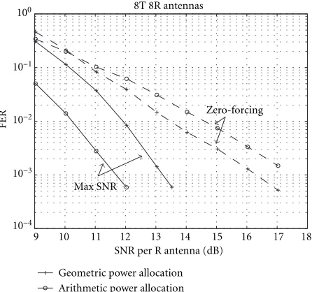
The design issues discussed in this paper are verified through simulation of an 8-transmit 8-receive multi-antenna system over a flat, Rayleigh, quasi-static (constant within a frame), and spatially independent channel. For the GST, we use sim-ilar simulation parameters as in [1]. That is, every transmit group contains two antennas; and a rate 1/2, 32-state, 4PSK space-time trellis code (Tarokh et al. in Figure 1) is used. The space-time codes for all groups are the same. Each frame consists of a total of 131 transmissions (128 data + 3 tail) from each transmit antenna. Using Figure 1 and the assump-tion of equally distributed source sequence, we have diagonal
E[c1
t(c1t)H]. The extreme case with one antenna per group, namely, the LST, encodes its in-phase and quadrature com-ponents separately using rate 1/2 binary convolutional codes with maximal minimum free distances. Again, all groups use the same code. Each frame still consists of 128 data trans-missions from each transmit antenna. The number of tail transmissions, however, depends on the allowable constraint lengths of individual systems.
9 10 11 12 13 14 15 16 17 18 SNR per R antenna (dB)
8T 8R antennas
Geometric power allocation Arithmetic power allocation
Zero-forcing
Max SNR
10−4
10−3
10−2
10−1
100
FER
Figure5: Performance comparison between zero-forcing and max-imum SNR methods.
array processing and geometrically decreasing power allo-cation (8 : 4 : 2 : 1) among groups is reproduced. We then apply maximum SNR array processing and/or an arith-metically decreasing power allocation (4 : 3 : 2 : 1) to the same system. In this figure, it is shown clearly that the maximum SNR approach outperforms the zero-forcing approach. When the same (geometric) power allocation is used, the maximum SNR approach is 1.5 dB better at 10−2
frame error rate (FER), and its advantage increases as the signal power increases due to the steeper FER slope. The steeper slope is a result of higher receive diversity, as the maximum SNR array processor does not preclude the re-ceived signal components lying in the interference space. The divergence of the asymptotic performances of the zero-forcing and the maximum SNR approaches might seem contradictory to the common understanding. It is, how-ever, necessary to clarify that the common understanding was built on the model which has a deterministic chan-nel gain. With the quasi-static, random chanchan-nel gains in our simulation, there is always a possibility that some of the channel gains are very small and the AWGN cannot be ignored, no matter how high the transmitted power is. It is these worst cases which limit the average error perfor-mance.
When arithmetic power allocation is applied, the maxi-mum SNR approach performs even better. Its gain over the zero-forcing method is 3 dB. As arithmetic power allocation is not matched to the zero-forcing diversity gains, it worsens the performance 1 dB at 10−2FER.
Figure 6 gives a comprehensive illustration of the de-sign issues discussed. First, three curves from Figure 5 are shown again to demonstrate the advantages of the maxi-mum SNR algorithm and the arithmetic power allocation, respectively. Then the performance when rotation is applied in addition to these two design considerations is shown
(dia-2 4 6 8 10 12 14 16 18
SNR per R antenna (dB) 10−4
10−3
10−2
10−1
100
FER
8T 8R antennas (FER)
Geo. power, ZF Geo. power, max SNR Ari. power, max SNR Ari. power, max SNR, rotate Code A, ari. power, max SNR, rotate Eq. power, iterative max SNR, rotate LST, ari. power, MMSE, rotate LST, eq. power, iterative MMSE, rotate Channel outage probability
Figure6: Performance when different design issues are considered.
mond marks). At 10−2FER, rotation gives about 1 dB gain.
The steeper slope of this configuration implies that rota-tion does increase the transmit diversity. A slight alterarota-tion of the Tarokh et al. code is also simulated. This code, re-ferred to as Code A in Figure 1, has encoder polynomi-als (defined in [8, page 757]): (2,2), (3,3), (2,0), (2,2), (1,1), (0,2), (2,1). It slightly outperforms the Tarokh et al. code.
The solid curve with square marks uses rotation and the iterative maximum SNR array processing and decoding de-scribed in Section 7. It has equal transmission powers for all groups. Due to the necessity of SISO decoding, the soft out-put Viterbi algorithm (SOVA) [22] is modified to generate soft outputs of the coded symbols. The SOVA decoding com-plexity is approximately twice the Viterbi decoder. Therefore, to maintain similar complexity, the space-time code used is the best 4-state code found in [23], and the number of ar-ray processing and decoding iterations is four. Group-based random temporal interleaving is applied to accelerate the de-coding convergence. Due to its extremely small constraint length, this system only shows a diversity gain similar to the non-iterative system without rotation. Nevertheless, iterative processing does improve the decoding performance when SNR is low.
7 8 9 10 11 12 13 14 SNR per R antenna (dB)
10−3
10−2
10−1
FER
2T 2R antennas (FER)
Space-time code (Tarokh) Space-time code (Code A) LST, MMSE, rotate LST, iterative MMSE, rotate Channel outage probability
Figure7: 2-transmit, 2-receive performance.
(658,578) (32 states). For fair comparison with the
corre-sponding GST cases, the power allocation of this system is the same (4 : 4 : 3 : 3 : 2 : 2 : 1 : 1). Its array process-ing method is MMSE. From Figure 6, we can see that the in-creased coding gain improves the performance. The slope of this curve, on the other hand, is very similar to the GST case with Code A. This is an implication that both codes (QPSK space-time code with constraint length 4 and binary convo-lutional code with constraint length 6) have the same degree of diversity after rotation.
The LST with iterative MMSE algorithm and equal group powers uses a (58,78) (4 states) convolutional code. The
number of decoding iterations is four. Random temporal in-terleaving is applied, separately and independently, to each of the four code streams (two in-phase, two quadrature) of ev-ery group. The performance of this system is about 2 dB bet-ter than the LST case with single-sweep decoding and hard decision feedback cancellation. As to the diversity gain, al-though this system has higher receive diversity due to better interference cancellation, its transmit diversity suffers from the shortened minimum free distance. The resultant perfor-mance slope of this system is very similar to that of the single-sweep LST case which has larger minimum free distance. At 10−2FER, this system is about 4 dB away from the channel
outage capacity [3, 4]. Figure 6 also shows that, due to either imperfect signal (code) design or sub-optimal decoding, all these practical systems do not achieve the performance slope given by information theory.
Similar experiment was conducted for the 2-transmit 2-receive case where the space-time coding (GST with one group) system uses optimal joint detection, while the LST suffers from inefficient interference suppression due to the small number of receive antennas (see Figure 7). With space-time coding being able to achieve maximum diversity, the
LST is not superior anymore. At 10−2FER, all these systems
are about 2.5 dB away from the channel outage capacity. They also seem to be able to achieve the information theoretic per-formance slope.
9. CONCLUSION
In this paper, we discussed some design issues of the open-loop space-time coded multi-antenna system. Through intu-itive, as well as analytical explanations, we revealed one by one the advantages of the design considerations. To summa-rize, the zero-forcing array processing method in [1] can be improved with a maximum SNR approach. This new array processing approach then necessitates a different power allo-cation among the transmission groups. To increase the trans-mit diversity when there are more than one group, group-based spatial interleaving (“rotation”) can be applied. We also considered the LST as a special case of the GST which has one antenna per group. When the number of receive antennas is large enough to resolve the transmission signal spaces, the LST allows easier code design and separate in-phase and quadrature encoding/decoding. These advantages can increase the coding gain and possibly the transmit diver-sity when the decoding complexity is constrained. The GST with maximum SNR array processing also finds itself a direct application of the iterative algorithm proposed in [13, 14]. In the 8-antenna LST example we gave, the iterative algorithm improves the performance about 2 dB.
APPENDIX
Proof of Theorem 1. We consider the linear filtering in two steps. First, a linear filter bankΘM(Ꮿ1) is used to filter the receive antenna outputs. The outputs of this filter bank are then combined to achieve maximum SNR. Without loss of generality, we assume that the interference components of the filter bank outputs are uncorrelated with one another. In other words, ΘH
M(Ꮿ1)RnΘM(Ꮿ1) is diagonal. This assump-tion is reasonable since for any filter bank consisting of k
linear filters, we can find, using the singular-value decom-position (SVD) [24] on ΘH
M(Ꮿ1)RnΘM(Ꮿ1), a nonsingular
k×kmatrix to transform it and diagonalize the interference covariance matrix of its outputs. This transformation is re-versible and does not destroy the information contained in the filter bank outputs.
As one of our goals is to minimize the number of linear filters required, we further assume that the linear filters of this filter bank are linearly independent of one another. If this is not true, we can always combine some of the filters to form a linearly independent filter bank with fewer filters.
With the above assumptions and the fact thatRnis non-singular, the filter bank outputs will have nonzero and un-correlated interference components. Under this condition, the maximum SNR combining of the filter bank outputs is maximum ratio combining. Given independent group trans-mission so that the signal and interference codeword (c1t and
filter bank satisfies
max w1,...,wk
j
wHjRswj subject to wHi Rnwi=ν, ∀i, (A.1)
whereνis a constant. With the quadratic form, this condition is equivalent to the following Lagrange multipliers
∂ ∂w∗i
j
wHjRswj−
j
λjwHjRnwj
=0, ∀i. (A.2)
The solutions to the Lagrange multipliers satisfy
Rs−λiRnwi=0, ∀i, (A.3)
with
λi=
wH i Rswi
wHi Rnwi
(A.4)
being the SNRs of the maximum SNR filter outputs. Clearly, we need only filters giving nonzero SNRs. To be consistent with the assumption of uncorrelated interference components, we can use Cholesky decompositionRn=LLH [24], asRnis Hermitian and positive definite. Premultiplying (16) byL−1, we get
CLHw=λLHw, (A.5)
where
C=L−1R
sL−1H (A.6)
is Hermitian and nonnegative definite with rankk. Accord-ing to (12), kcan be no larger than the rank of Ω(Ꮿ1), so
k ≤min(m, n1). The eigenvalues ofCare the same as those of the original problem (16). There areknonzero eigenval-ues, and a set of orthogonal eigenvectors{LHw
i}ki=1 can be
found by using SVD. It is then straightforward that
wHi Rnwj=
ν, i=j,
0, i=j, w
H i Rswj=
λiν, i=j, 0, i=j. (A.7)
Since
EwH
i rtrHt wj=wiHRs+Rnwj, (A.8) then the filter bank outputs are uncorrelated with one an-other.
ACKNOWLEDGMENTS
This work was presented at the IEEE International Confer-ence on Third Generation Wireless Communications, San Francisco, California, USA, June 2000.
This work was supported in part by NASA through con-tract NCC3528 and in part by the Army Federated Lab through CTA contract DAAD19-01-2-0011.
REFERENCES
[1] V. Tarokh, A. Naguib, N. Seshadri, and A. R. Calderbank, “Combined array processing and space-time coding,” IEEE Transactions on Information Theory, vol. 45, no. 4, pp. 1121– 1128, 1999.
[2] G. J. Foschini, “Layered space-time architecture for wireless communication in a fading environment when using multi-element antennas,” Bell Labs Technical Journal, vol. 1, no. 2, pp. 41–59, 1996.
[3] G. J. Foschini and M. J. Gans, “On limits of wireless commu-nications in a fading environment when using multiple an-tennas,” Wireless Personal Communications, vol. 6, no. 3, pp. 311–335, 1998.
[4] E. Teletar, “Capacity of multi-antenna Gaussian channels,” Tech. Rep., Internal Tech. Memo., AT&T-Bell Labs, June 1995. [5] N. Seshadri and J. H. Winters, “Two signaling schemes for im-proving the error performance of frequency-division-duplex (FDD) transmission systems using transmitter antenna diver-sity,” International Journal of Wireless Information Networks, vol. 1, no. 1, pp. 49–60, 1994.
[6] A. Wittneben, “Base station modulation diversity for digital SIMULCAST,” inProc. IEEE Vehicular Technology Conference, pp. 505–511, Secaucus, NJ, USA, May 1993.
[7] A. Wittneben, “A new bandwidth efficient transmit antenna modulation diversity scheme for linear digital modulation,” inProc. IEEE International Conference on Communications, pp. 1630–1634, Geneva, Switzerland, June 1993.
[8] V. Tarokh, N. Seshadri, and A. R. Calderbank, “Space-time codes for high data rate wireless communication: perfor-mance criteria and code construction,” IEEE Transactions on Information Theory, vol. 44, no. 2, pp. 744–765, 1998. [9] J.-C. Guey, M. P. Fitz, M. R. Bell, and W.-Y. Kuo, “Signal
de-sign for transmitter diversity wireless communication systems over Rayleigh fading channels,”IEEE Trans. Communications, vol. 47, no. 4, pp. 527–537, 1999.
[10] S. M. Alamouti, “A simple transmit diversity technique for wireless communications,” IEEE Journal on Selected Areas in Communications, vol. 16, no. 8, pp. 1451–1458, 1998. [11] V. Tarokh, H. Jafarkhani, and A. R. Calderbank, “Space-time
block codes from orthogonal designs,” IEEE Transactions on Information Theory, vol. 45, no. 5, pp. 1456–1467, 1999. [12] A. R. Hammons, Jr. and H. El Gamal, “On the theory of
space-time codes for PSK modulation,”IEEE Transactions on Infor-mation Theory, vol. 46, no. 2, pp. 524–542, 2000.
[13] X. Wang and H. V. Poor, “Iterative (Turbo) soft interfer-ence cancellation and decoding for coded CDMA,” IEEE Trans. Communications, vol. 47, no. 7, pp. 1046–1061, 1999. [14] H. El Gamal and E. Geraniotis, “Iterative multi-user
detec-tion for coded CDMA signals in AWGN and fading channels,” IEEE Journal on Selected Areas in Communications, vol. 18, no. 1, pp. 30–41, 2000.
[15] M. L. Honig, U. Madhow, and S. Verd ´u, “Blind adaptive mul-tiuser detection,” IEEE Transactions on Information Theory, vol. 41, no. 4, pp. 944–960, 1995.
[16] H. V. Poor and S. Verd ´u, “Probability of error in MMSE mul-tiuser detection,” IEEE Transactions on Information Theory, vol. 43, no. 3, pp. 858–871, 1997.
[17] V. Tarokh and T. K. Y. Lo, “Principal ratio combining for fixed wireless applications when transmitter diversity is employed,” IEEE Communications Letters, vol. 2, no. 8, pp. 223–225, 1998. [18] H. El Gamal and A. R. Hammons Jr., “A new approach to lay-ered space-time coding and signal processing,” IEEE Trans-actions on Information Theory, vol. 47, no. 6, pp. 2321–2334, 2001.
for wireless communications: performance analysis and de-sign criteria,” inProc. IEEE Wireless Communications and Networking Conference, pp. 159–163, New Orleans, La, USA, September 1999.
[20] J. Hagenauer, E. Offer, and L. Papke, “Iterative decoding of binary block and convolutional codes,” IEEE Transactions on Information Theory, vol. 42, no. 2, pp. 429–445, 1996. [21] F. Tark¨oy, “MMSE-optimal feedback and its applications,” in
Proc. IEEE International Symposium on Information Theory, p. 334, Whistler, Canada, September 1995.
[22] J. Hagenauer and P. Hoeher, “A Viterbi algorithm with soft-decision outputs and its applications,” inProc. GLOBECOM ’89, pp. 1680–1686, Dallas, Tex, USA, November 1989. [23] S. B¨aro, G. Bauch, and A. Hansmann, “Improved codes for
space-time trellis-coded modulation,” IEEE Communnica-tions Letters, vol. 4, no. 1, pp. 20–22, 2000.
[24] S. Haykin, Adaptive Filter Theory, Prentice-Hall, Englewood Cliffs, NJ, USA, 3rd edition, 1996.
Hsuan-Jung Sureceived his B.S. degree in electronic engineering from the National Chiao-Tung University, Taiwan, in 1992, and the M.S. and Ph.D. degrees in electrical engineering from the University of Mary-land, College Park, in 1996 and 1999, re-spectively. From 1999 to 2000, he was a Postdoctoral Research Associate with the Institute for Systems Research, University of Maryland. Since November 2000, he has
been with Bell Laboratories, Lucent Technologies, Holmdel, New Jersey, where he has been involved in the design and perfor-mance evaluation of adaptive coding/modulation, fast Hybrid-ARQ, scheduling, and Radio Link Control protocol for 3G wireless networks. His research interests cover coding, modulation, signal processing, power control and synchronization of narrowband and wideband communication systems.