SWIFFT / SWIFFTX Hash Functions
Tam´as Gy¨orfi1,2, Octavian Cret¸2, Guillaume Hanrot3, and Nicolas Brisebarre3
1
National Instruments Romania, Cluj-Napoca branch, B-dul Corneliu Coposu, nr. 167A, et.I,
Cluj Napoca, Romania [email protected]
2 Technical University of Cluj-Napoca - Romania, Computer Science Department, 26-28 George Bariiu street,
400027 Cluj-Napoca, Romania [email protected]
3 LIP/AriC, (CNRS – ENS Lyon – INRIA – UCBL), ENS Lyon, 46, all´ee d’Italie,
F-69364 Lyon Cedex 07, France
{Guillaume.Hanrot,Nicolas.Brisebarre}@ens-lyon.fr
Abstract. Introduced in 1996 and greatly developed over the last few years, Lattice-based cryptography offers a whole set of primitives with nice features, including provable security and asymptotic efficiency. Going from “asymptotic” to “real-world” efficiency seems important as the set of available primitives increases in size and functionality. In this present paper, we explore the im-provements that can be obtained through the use of an FPGA architecture for implementing an ideal-lattice based cryptographic primitive. We chose to target two of the simplest, yet powerful and useful, lattice-based primitives, namely the SWIFFT and SWIFFTX primitives. Apart from being simple, those are also of central use for future primitives as Lyubashevsky’s lattice-based signatures. We present a high-throughput FPGA architecture for the SWIFFT and SWIFFTX primitives. One of the main features of this implementation is an efficient implementation of a variant of the Fast Fourier Transform of order 64 onZ257. On a Virtex-5 LX110T FPGA, we are able to hash 0.6GB/s, which shows a ca. 16×speedup compared to SIMD implementations of the literature. We feel that this demonstrates the revelance of FPGA as a target architecture for the implementation of ideal-lattice based primitives.
Keywords:Lattice-based cryptography, Provably secure, Hardware accel-erator, FPGA, FFT, Hash functions
1 Introduction
Lattice-based cryptography (see [25] for a beautiful survey) has been developing at a quick pace over the last fifteen years since the seminal paper by Ajtai [2]. Its main attractive features, among others (including no known quantum attack at the time this paper is written) are probably rigorous asymptotic security analyses and asymptotic efficiency.
finding a shortest non-zero vector of a lattice in the`2 norm, known to be NP-hard under randomized reductions. The cryptographer then only has to prove the equivalence of breaking the cryptosystem and solving a random instance of either SIS or LWE to get a strong asymptotic security guarantee.
As for efficiency, it should be noted that the basic operation in lattice-based cryptography is a matrix-vector product, which has quadratic complexity in the size of the vector. This complexity was actually lowered to quasi-linear through the introduction of structured matrices, idea which originated in the well-known NTRU cryptosystem [16] and was revived by Micciancio, who introduced ma-trices with a specific block-Toeplitz structure, namelynegacyclic structure1. As the product of such a matrix by a vector amounts to computing a product of two polynomials modulo Xn+ 1, one can get a quasi-linear computation time via the use of an FFT-type algorithm for multiplying polynomials. This has given rise to the definition and study of the hardness of structured variants of the LWE [23] and SIS [21, 27] problems, which have proven to be as versatile as their purely linear counterparts and to enjoy similar security reductions, while offering cryptographic primitives with asymptotic quasi-linear complexity.
However, envisioning the deployment of lattice-based cryptography requires a practical, not only asymptotic, assessment of its parameters in order to reach a good efficiency/security compromise. By using the explicit reductions from the cryptosystems to classical lattice problems such as SIVPγ (a variant of the
Shortest nonzero Vector Problem, see e.g. [25]), one can derive rather pre-cise estimates for security of lattice-based primitives, using the significant body of work performed on lattice basis reduction and enumeration of short vectors. Such studies of lattice problems and the impact they have on parameters choice for lattice-based cryptography have been made on a variety of platforms, see e.g. for CPUs [5, 8, 11, 19, 25], for GPUs [14, 15, 18] and for FPGA [9]. How-ever, the assessment of the efficiency of (ideal-) lattice-based primitives does not seem to have given rise to much interest, except in software (CPU), though significant activity has been observed over the last months concerning homo-morphic encryption, see e.g. [12, 26, 32]. In particular, this raises an important question on what various architectures (CPU, GPU, FPGA) can bring (advan-tages and drawbacks) as far as implementation of ideal-lattice-based primitives are concerned.
The main purpose of this paper is to study the relevance of FPGA imple-mentation for an ideal-lattice-based cryptography primitive, and to compare it with highly optimized software implementation. In order to do this, we de-scribe a high-throughput architecture for the simplest, though powerful and useful, of the lattice-based primitives, namely the SWIFFT [22] hash function and its improved version SWIFFTX [4]. The former enjoys a security prooffor its collision-resistance properties (which is both desirable and highly unusual for a hash function), whereas the latter is an extension of the former, adding some scrambling steps to avoid undesirable linearity properties. Further, SWIFFT is used in other important cryptographic primitives such as Lyubashevsky’s
signature algorithm2 [20]. The present work can thus be considered as a first step towards the implementation of more advanced lattice-based primitives. Our major contributions to the high throughput hardware implementation of the SWIFFT and SWIFFTX hash functions can be summarized as follows:
– Pipelined implementation of the modular Fast Fourier Transform over Zp,
p= 2k+ 1, using the diminished-one number system;
– Packing the SWIFFT function descriptor constant coefficient multipliers into BlockRAM primitives;
– DSP overclocking for hardware reuse;
– Pipelined implementation of the ConvertToBytes function.
The paper is organized as follows: Section 2 presents an overview of the SWIFFT hash function introduced in [22], and briefly argues the choice to stick to the original SWIFFT parameters. Section 3 describes our high-throughput hardware implementation for the modular FFT. Though we restrict to the orig-inal SWIFFT parameters, it must be pointed that the FFT is a basic building block for all ideal-lattice based cryptography. Section 4 shows the proposed architecture for the SWIFFT hash function. Section 5 presents the hardware architecture for the SWIFFTX hash function which uses SWIFFT as its basic building block. Experimental results are shown in Section 6, while concluding remarks and future work are presented in Section 7.
2 The SWIFFT hash function
2.1 Description of SWIFFT
Let n be a power of 2, p a prime number such that 2n|p−1, and R be the ring Zp[α]/(αn+ 1), which can be identified to the set of polynomials overZp
with degree< n. Letm be an integer such that m≥logp. The SWIFFT hash function with parametersn, m, ptakes as inputmelements ofR, and computes a linear combination of those with prescribed coefficientsA= (A0, . . . , Am−1)∈
Rm, namely
SWIFFTA(x0, . . . , xm−1) =
m−1
X
i=0
Ai×xi, (1)
where, in order to hash a binary string, the input messageµis cut into chunks ofmn bits, which are in turn interpreted as the binary polynomials
(x0, . . . , xn−1) = (µ0+µ1α+· · ·+µn−1αn−1, µn+· · ·+µ2n−1αn−1, . . . , µ(m−1)n+· · ·+µmn−1αn−1)∈Rm.
In particular, SWIFFT hashesmnbits to ndlogpe bits.
2
Note that though Lyubashevsky does not directly point SWIFFT, one of the basic opera-tions of his signature algorithm amounts to computeA·y modq, which is the same ifA
2.2 FFT aspects of SWIFFT
As pointed in [22], the polynomial products in Equation (1) can be efficiently computed using (part of) a 2n-order Discrete Fourier Transform (DFT) per-formed overZp (sometimes referred to asNumber Theoretic Transform (NTT),
see eg. [29]). Let ω be a primitive 2n-th root of unity lying in some extension field Fof Zp. Define ODFT2n,ω(P) by
ODFT2n,ω n−1
X
i=0 uiXi
!
=
n−1
X
j=0
ω(2k+1)juj
0≤k≤n−1
=
n−1
X
j=0 ω2kj
(ωjuj)
0≤k≤n−1
.
As suggested by the last equality, this modified DFT can be computed by the classical FFT algorithm [6], with order n and primitive root ω2, ap-plied to the polynomial Pn−1
i=0 ωiuiXi. This requires a quasi-linear number of operations in the field F. Further, ODFT is suited to computing
polyno-mial products modulo Xn+ 1 (our goal here), since it is readily checked that
ODFT2n,ω(P·Qmod (Xn+1)) = ODFT2n,ω(P)?ODFT2n,ω(Q), where?stands
for the componentwise multiplication of vectors.
The setting where p= 1 mod 2n is especially favourable since in that case
Zp contains a 2n-th primitive root of unityω, so that we have F=Zp. All the
underlying FFT computation is thus performed by arithmetic overZp. Further
note that such moduli (powers of 2 plus one – recall thatnis a power of 2) are also well-suited to efficient implementation of modular reduction.
A slight change of definition of the SWIFFT function allows for further op-timizations, see [22]. Indeed, as the multipliersAiare fixed in advance, it is
pos-sible to store their Fourier representation instead of evaluating it3. Also, since ODFT is a bijection between Znp and polynomials over Zp of degree < n, the
hash value can be represented by the value ODFT(SWIFFT(u0, . . . , un−1)) (in other words, in the Fourier domain) and there is no need to compute the inverse FFT; in the sequel, we shall denote this output FFT vector by (Z0, . . . , Zn−1). Based on the above observations, the algorithm for computing the hash value can be formulated as follows:
Input : String to be hashed, seen as an element of{0,1}n×m.
Output : The hash value (Z0, ..., Zn−1)∈Znp
’Diffusion’ step:
Multiply theithrow of the input matrix byωi;
Apply the ODFT over each column of the resulting matrix:
(Y0,j, ..., Yn−1,j) =ODF T(ω0·x0,j, ..., ωn
−1
·xn−1,j). ’Confusion’ step:
Multiply theithcolumn by the elementAi,j; Compute the sum of the elements on a row:
Zi= m−1
X
j=0
Ai,j×Yi,j.
Algorithm 1: The SWIFFT hash function algorithm
3 or, instead, to choose the Fourier transform ˆA
i uniformly at random instead of choosing
2.3 Parameter choice for FFT/SWIFFT
Based on security as well as performance considerations, the authors of [22] propose the following concrete parameters for the hash function: n= 64, m= 16, p= 257. Indeed, as was previously pointed, since p = 1 mod 2n, for these parameter values, one can use ω = 42 ∈ Zp, and the function maps a binary
input of lengthm×n= 1024 bits to an output vector in the rangeZnp that can
be represented on 520 bits.
The original paper and the survey [25] argue that those parameters guaran-tee strong security (the latter mentionning a 100-bit equivalent for the symmet-ric security corresponding to enumeration attacks). Recent work by Buchmann and Lindner [5] argues that those parameters only provide roughly 68 bit of symmetric security. However, this security analysis accounts for the resistance to pseudo-collisions (roughly speaking, collisions where thexi are “small” but
not restricted to {0,1}), whereas the security level for resistance to real colli-sions seems to remain higher than 100 bits. For this reason, but also because we wanted to stick to the original parameters of SWIFFT in order to be able to plug the latter into SWIFFTX, we stick to those parameters values in the sequel.
3 Hardware architecture for the FFT
The performance of the modular FFT depends on the efficient implementation of the basic modular arithmetic operators such as addition and multiplication inZp. This section describes the proposed implementation of the modular
arith-metic operators, and, based on them, presents a high-throughput design for the FFT.
3.1 Modular Arithmetic Operators Implementation
All arithmetic operations involved in the transform are performed over theZp
field. We shall use here the fact that the standard value of p for SWIFFT, 257, is equal to 28+ 1. Note that this is a strong requirement, as conjecturally, only finitely many (and probably very few) prime numbers of that form (the so-called Fermat primes) do exist.
As proposed in [1], an efficient way to represent numbers modulop= 2k+ 1 is to apply the diminished-one number system, where a non-zero number A is represented asAdim:=A−1 on log2(p) bits, while number zero is indicated by a special flagA.z. We will denote the tuple (Adim,A.z) byA0.
Modular Addition and Subtraction Modular addition in this system can be carried out as follows [1]:
Sdim= (Adim+Bdim+ 1)[2k+ 1] = (Adim+Bdim+cout)[2k], (2)
where Sdim is the diminished-one representation of the sum A+B while cout
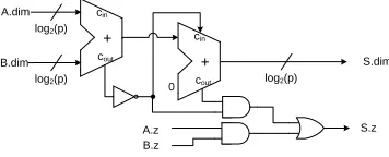
represents the carry-out bit of the additionAdim+Bdim. Besides implementing Equation (2), the modular adder must have a zero-detection circuit that asserts the zero flag. The design of the modular adder is shown in Figure 1.
log2(p) A.dim
A.z B.dim
B.z
log2(p) log2(p)
S.dim
S.z
+
cin
cout +
cin
cout
0
Fig. 1.Architecture of the modular adder unit based on diminished-one representation
Modular Multiplication The FFT requires the evaluation of polynomials at the nroots of unity, i.e. ω0, ω2, . . . , ω2n−2. Besides additions and subtractions, this evaluation requires multiplication of the polynomial coefficients by the roots of unity at a certain power that can be considered as constants (ω = 42 for our parameter choice).
We considered several modulo 2k+ 1 multiplier architectures based on the techniques proposed in [7] and [35]. These techniques can be divided into four classes as follows:
1. Multiplication by means of lookup tables, where the operands form the address of the lookup table and the content of the table stores the product. 2. Quarter-squared method that uses lookup tables for evaluating (A/2)2. Then, the product of two arbitrary numbers is computed based on the equa-tion:
(A×B)[2k+ 1] =
A+B 2
2
−
A−B 2
2!
[2k+ 1].
3. Multiplication byk×k bits multiplier using the following equation:
(A×B)[2k+ 1] = ((A×B) mod 2k−(A×B) div 2k)[2k+ 1]. (3)
4. Rewrite modular multiplication as a sum of partial products. If A =
Pk−1
i=0 2iai and B =
Pk−1
i=0 2ibi:
(A×B)[2k+ 1] = (
k−1
X
i=0
(P Pi+ 1) + 2)[2k+ 1],
P Pi=ai·bk−i−1. . . b0bk−1. . . bk−i+ai·0. . .0
| {z }
k−i
1. . .1
| {z }
i
.
The multiplication methods were evaluated for the cases when both operands are variable and also when one of the operands is constant. The area utilizations of the multiplication methods expressed as the number of 6-input LUTs are given in Table 1.
Based on the concrete parameters for SWIFFT (k= 8), we implemented the modular multiplication by ω2i by means of lookup tables. Figure 2 shows the design of this multiplier, where the ith ROM block stores the diminished-one representation of the product resulting from the multiplication of all non-zero numbers modulo p by ω2i. The zero flag of the product is asserted only if the input zero flag is asserted (ω2i is non-zero for all i). Thus, the zero flag does
Table 1.Number of FPGA lookup tables (LUT) required for modulo (2k+ 1) multiplier
Method Variable inputs Constant coefficient
k= 8 k= 16 k= 8 k= 16 Lookup tables 8×10³ 1×10⁹ 32 16×103 Quarter-squared 158 32×103 32 16×103 Multiplier-based 105 345 35 63 Partial product-based 72 145 N/A N/A
ROMi
0 * ω2i [p]
1 * ω2i
[p]
addr. 0
addr. 1
(p-1) * ω2i
[p]
addr. p-1
log2(p) bits
log2(p)
A.dim
log2(p)
P.dim
A.z P.z
. . .
Fig. 2.Constant coefficient modular multiplier implemented by means of lookup tables
3.2 Overall FFT Architecture
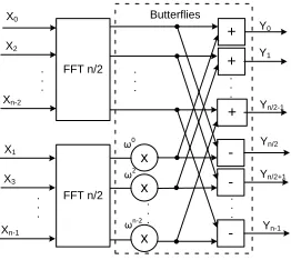
Most of the FFT architectures reported in the literature apply a recursive de-composition of the problem into multiple butterfly stages as shown in Fig-ure 3 [6]. The hardware implementation can be iterative, serial or pipelined, mostly depending on the sizenof the transform, and the input pattern [17, 24]. Also, a distributed serial arithmetic approach [28, 33] would be feasible in this particular case.
+ +
+
. . .
-. . .
x x x
ω0
ω2
ωn-2
FFT n/2 . . .
. . .
X0
X2
Xn-2
X1
X3
Xn-1
Y0
Y1
Yn/2-1
Yn/2
Yn/2+1
Yn-1
Butterflies
. . . FFT n/2
. . .
Fig. 3.Traditional implementation of the FFT
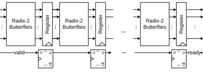
Considering the size of the transform required for SWIFFT (n = 64) and that the algorithm applies the transform multiple times, we opted for a Radix-2 decomposition pipelined architecture consisting of log2(n) butterfly stages where each stage consists of n/2 butterflies. The control logic for the FFT is implemented using thevalid-ready handshaking protocol, as shown in Figure 4.
Radix-2 Butterflies
R
e
g
is
te
r
...
... ... ButterfliesRadix-2
R
e
g
is
te
r
...
... ... ButterfliesRadix-2
R
e
g
is
te
r
...
... ...
Q Q SET
CLR D
Q Q SET
CLR D
Q Q SET
CLR D
valid ready
...
...
Fig. 4.Pipelined FFT architecture
Note that this FFT architecture could still be optimized in terms of latency -one possible improvement could consist in reducing the overall latency by imple-menting an FFT of degree 8 by means of lookup tables instead of the traditional decomposition into FFTs of degree 4 and 2. This would reduce the latency by 2 cycles but it would increase the FPGA device resource consumption.
4 Hardware architecture for SWIFFT
As presented in Section 2, the SWIFFT hash function performs FFTsm times to compute the Fourier coefficients of each polynomial of degree < n formed by the input message bits. The overall time needed to execute all the FFT transforms for SWIFFT is m + log2(n) cycles.
4.1 Multiplication by the function descriptor matrix
After obtaining the Fourier coefficientsY0,j, ..., Yn−1,jof the polynomials formed
by input coefficients X0,j, ..., Xn−1,j, these coefficients are multiplied by the
function descriptor elements A0,j, ..., An−1,j. The resulting products are
accu-mulated forj = 0, ..., m−1 to obtainZi:
Zi =
m−1
X
j=0
Ai,j×Yi,j. (4)
Considering that Yi,j is represented in diminished-one format, Equation (4)
becomes:
Zi0 =
m−1
X
j=0
(Ai,j×Yi,j0 + 1) +
m−1
X
j=0
A0i,j. (5)
The pipelined implementation of the FFT proposed in Section 3 computes a new set of Fourier coefficients in each clock cycle. Hence, Equation (5) can be efficiently implemented in hardware as a Multiply-Accumulate unit (MAC) consisting of a pipelined modular multiplier, modular adder and the internal register. The Fourier coefficients generated throughout themconsecutive clock cycles are multiplied by their corresponding function descriptor element and the product is accumulated using the diminished-one modular adder. The second term of Equation (5) is a constant and can be set as the synchronous reset value of the internal register.
in the FFT pipeline. The overall throughput of the MAC thus becomesm+ 1 cycles per sample.
Figure 5 shows the SWIFFT architecture that consists of the FFT and MAC components.
Y’0
Y’n-1
FFT n
X’0 X’n-1 . . . . . .
x + Z’0
0
ω0
xn-1
,m -1 .. . 0 ωn-1 A0 ,0 A0 ,1 A0 ,m -1 .. . R e g
x + Z’n-1
An -1 ,0 An -1 ,1 An -1 ,m -1 .. . R e g
xn-1
,1
xn-1
,0
x0,m
-1
..
. x0,1 x0,0
MAC
1 0 , 0 ' m j j A 1 0 , 1 ' m j j n A
Fig. 5.Overall hardware architecture for the SWIFFT hash function
We considered two approaches for implementing the multipliers inside the Multiply-Accumulate Unit (first term in Equation (5)) having different area and performance trade-offs. In the first approach, we treat the function descriptors Ai,j as constants and implement constant coefficients multipliers by means of
lookup tables, similar to the one shown in Figure 2. The benefit of this approach is that the memory can store the modulo reduced products in diminished-one format and thus multiplication is executed in one clock cycle. However, this option also implies implementingm×nmemories of size 2k×(k+ 1) bits.
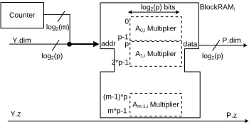
Based on the parameters proposed for SWIFFT in [22], this is still feasible: the memories evaluating the product of all the Fourier coefficients at a certain indexican be efficiently packed into a single Xilinx BlockRAM primitive inside the FPGA chip. Thus, we obtain a multiplier structure as shown in Figure 6.
BlockRAMi
Am-1,i Multiplier
log2(p) bits
log2(p)
Y.dim
log2(p)
P.dim
Y.z P.z
A1,i Multiplier
A0,i Multiplier
0 p-1 (m-1)*p m*p-1 addr data Counter
log2(m)
p
2*p-1
Fig. 6. Multiplier by function descriptor elements A0,i, ..., Am−1,i packed into BlockRAM primitive
If the size of the function descriptor Ai,j is larger or if there are multiple
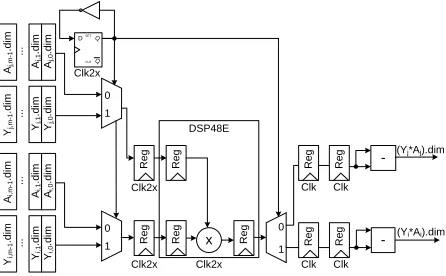
The second approach consists in applying an unsigned k×kbits multiplier and computing the modulo reduced product based on Equation (3). An efficient solution for implementing the multiplier is to use the DSP primitives dedicated for this purpose. The DSP48E slices of a Xilinx FPGA can operate at a higher frequency compared to other primitives - in order to reduce the overall number of required DSP48E slices, it is possible to overclock these primitives to execute two multiplications per cycle [34]. Registers are inserted at the input and the output of the DSP48E blocks which, together with the embedded registers, form double synchronizers that transfer data from/to the double-frequency clock do-main. The final architecture of the modular multiplier is shown in Figure 7. Thus, the overall number of DSP48E blocks required for SWIFFT isn/2.
DSP48E
- (Yj*Aj).dim
Clk2x Clk2x R e g Q Q SET CLR D Yi, 0 .d im Yi, 1 .d im Yi, m -1 .d im .. . Ai, 0 .d im Ai, 1 .d im Ai, m -1 .d im .. . 0 1 Yj, 0 .d im Yj, 1 .d im Yj, m -1 .d im .. . Aj, 0 .d im Aj, 1 .d im Aj, m -1 .d im .. . 0 1 Clk2x R e g R e g R e g Clk2x R e g 0 1 x Clk R e g Clk R e g Clk
(Yi*Ai).dim
Clk R e g -R e g
Fig. 7.Implementation of modulo 2k+ 1 multiplier using overclocked DSP48E primitive
4.2 Overall SWIFFT Architecture
The overall hardware architecture for SWIFFT is shown in Figure 5. We opted for the BlockRAM-based implementation of the MAC multipliers (the first ap-proach) having one cycle latency. The input message is read in n-bit blocks throughmconsecutive cycles. The input multiplexers implement the multiplica-tion of the input polynomial coefficient bits byωi. The output of the multiplexer is already represented in the diminished one format. The FFT starts processing one n-bit block of the input message in each clock cycle and has a latency of log2(n) cycles. The MAC accumulates the Fourier coefficients to generate the final hash value. The overall execution time of SWIFFT is log2(n) +m+ 2 cycles. The hash value obtained is represented in the diminishedone format -converting it back to the normal representation is covered in the next section.
5 Hardware architecture for the SWIFFTX hash function
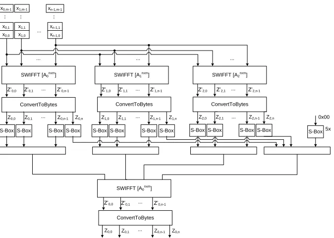
1. An inner layer of 3 parallel invocations of SWIFFT on the same input data with different function descriptor matrices;
2. An intermediary layer that converts the output of the inner layer from modulo p to binary and applies S-boxes to break the linearity property of SWIFFT;
3. An outer layer consisting of a single invocation of SWIFFT on the output of the intermediary layer.
SWIFFT [A0nxm]
x0,0
x0,1
x0,m-1
...
x1,0
x1,1
x1,m-1
...
xn-1,0
xn-1,1
xn-1,m-1
...
...
SWIFFT [A1nxm] SWIFFT [A2nxm]
... ... ...
ConvertToBytes Z’0,0 Z’0,1 Z’0,n-1
ConvertToBytes Z’1,0 Z’1,1 Z’1,n-1
ConvertToBytes Z’2,0 Z’2,1 Z’2,n-1
...
... ...
Z0,0 Z0,1 ... Z0,n-1 Z0,n Z1,0 Z1,1 ... Z1,n-1 Z1,n Z2,0 Z2,1 ... Z2,n-1 Z2,n
S-Box S-Box S-Box S-Box S-Box S-Box S-Box S-Box S-Box S-Box S-Box S-Box
SWIFFT [A0nxm]
S-Box 0x00
5x
ConvertToBytes Z’0,0 Z’0,1 ... Z’0,n-1
Z0,0 Z0,1 ... Z0,n-1 Z0,n
Fig. 8.The SWIFFTX compression function
The proposed hardware implementation follows a data-flow architecture where all the three layers are placed on a single FPGA chip and intercon-nected by pipeline registers. This leads to an increased area/throughput ratio, but it also results in a high-throughput architecture. In order to process the in-put message at a fixed rate without additional storage requirements, the three SWIFFT invocations in the inner layer have to be executed in parallel. Consid-ering the SWIFFT architecture proposed in Section 4.2 (Figure 5), it is clear that the component implementing the FFT can be shared across the three in-stantiations. Hence, only the multiply-accumulate units that perform the linear combination by the function descriptor matrices have to be instantiated three times.
1. the DSP48E blocks are overclocked to multiply two Fourier coefficients per cycle;
2. the DSP48E input port is divided into upper and lower 16-bit words, so that it multiplies one Fourier coefficient by two elements from different function descriptors,A0i,j and A1i,j.
The output of the inner layer is comprised of elements inZ257 that need to be converted into binary qauntities for further use. This is done by the so-called ConvertToBytes function introduced in [4] which is an injective mapping ofn= 64 elements of Z257 into 65 bytes. The ConvertToBytes function performs the change of base from 257 to 256 by taking groups of 8 elementsZi0, ..., Zi0+7 ∈Z257 and producing 8 elementsZi, ..., Zi+1∈Z256 and a bitbbased on the following formula:
7
X
i=0
Zi0×257i = 7
X
i=0
Zi×256i+b×2568. (6)
Then, each of the outputsZi∈Z256are fed to an S-box that performs a simple permutation over {0,1}8. The additional bits b generated by the execution of the ConvertToBytes function are combined over 8 groups to form a byte. This combined byte is then also permuted by the S-box. Finally, the algorithm executes SWIFFT over the output bytes produced by the S-box.
Based on Equation (6),Zi∈Z256can be expressed as shown in the equations below:
σ−1 = 0, σi×256 +Zi=
7
X
k=i
(
k i
×Zk0) +σi−1 fori= 0, . . . ,7, b=σ7. (7)
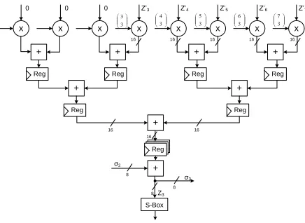
As allZk0 become available in the same cycle, we implement Equation (7) as a pipelined accumulator using a binary tree of 16-bit adders to computeZi. The
generic design for Z3 is shown in Figure 9.
+ x 0 x 0 x 0 x 3 3 Z’3 x 3 4 Z’4 x 3 5 Z’5 x 3 6 Z’6 x 3 7 Z’7 + + +
Reg Reg Reg Reg
+ + + + Reg Reg σ2 σ3 Z3 8 8 8 S-Box 16 16 Reg Reg Reg 16
16 16 16 16 16
Fig. 9.Pipelined Multiply-Accumulate Unit for computingZ3in the ConvertToBytes function
on the datapath in order to compensate the delay. The proposed hardware architecture for the intermediary layer consists of a pipelined implementation of the ConvertToBytes function over one group of 8 elements and 8 S-box instances implemented as lookup tables that permute the outputs of the ConvertToBytes function.
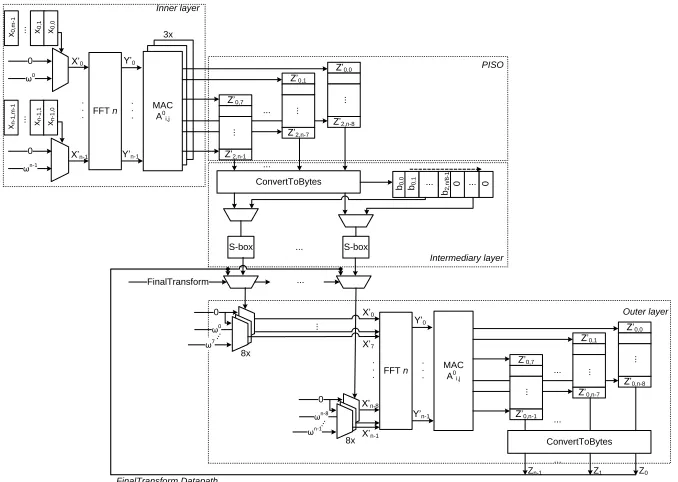
The connection between the inner and intermediary layers is realized through 8 parallel-in serial-out shift registers. The output of the intermedi-ary layer is fed to the outer layer instantiation of SWIFFT.
The overall SWIFFTX architecture is shown in Figure 10. Note that the SWIFFTX hash function has as its final step the so-called FinalTransform pro-cedure. This procedure converts the final 520-bits output of the hash function into 512 uniformly distributed bits. Due to resource limitation, this transform step is still implemented in software. Considering that it is invoked only after the entire message has been hashed, this would not have a significant impact on the function’s throughput when hashing long messages.
MAC A0 i,j MAC A0 i,j Y’0 Y’n-1 FFT n X’0 X’n-1 . . . . . . 0 ω0
xn-1
,m -1 .. . 0 ωn-1
xn-1,1
xn-1,0
x0,m
-1
..
.
x0,1
x0,0
MAC A0 i,j Z’0,0 ConvertToBytes Z’0,1 Z’0,7 Z’2,n-8 Z’2,n-7 Z’2,n-1 S-box S-box ... ... ... Y’0 Y’n-1 FFT n X’0 X’n-8 . . . . . . MAC A0 i,j Z’0,0 ConvertToBytes Z’0,1 Z’0,7 Z’0,n-8 Z’0,n-7 Z’0,n-1 ... ... 3x ... Inner layer Intermediary layer Outer layer ... ... ... ... ... ... ω0 0 ω7 8x ... ωn-8 0 ωn-1 8x ... X’7 ... X’n-1
b2,n/8
-1
b0,0
b0,1 ... 0 ... 0
Zn-1 Z1 Z0
PISO
FinalTransform ...
FinalTransform Datapath
Fig. 10.Hardware architecture for the SWIFFTX hash function
6 Experimental Results and Analysis
SWIFFT, the parameters of the function were set as proposed in [22], i.e. n= 64, m= 16, p= 257 and ω= 42.
The function descriptor multipliers are implemented using the BlockRAM-based approach that has one cycle latency. For SWIFFTX, parametermis set to 32 as proposed in [4] and the function descriptor multipliers are implemented in DSP48E blocks. Both hash functions use the same implementation of the FFT. The resource utilizations obtained for the FFT, SWIFFT and SWIFFTX4 hash functions are presented in Table 2. In our implementation, the FFT core is optimized for maximum throughput - this is achieved by the Radix-2 pipelined decomposition consisting of (n/2)·log2(n) butterfly operators suited for small values of n (n ≤ 64). If n is further increased, it will be necessary to explore different techniques for executing the FFT. On the other hand, increasing pa-rameter m impacts only the execution time of the algorithm but it does not affect the resource requirements significantly.
Table 2.Resource utilization for FFT, SWIFFT and SWIFFTX cores on Virtex-5 LX110T
Core Slices BlockRAM DSP48E Cycles/sample Latency (cycles) Frequency (MHz) FFT 3,639 (21%) 68 (23%) 0 (0%) 1 log2(n) 150 SWIFFT 4,004 (23%) 96 (32%) 0 (0%) m+ 1 m+ log2(n) + 1 150 SWIFFTX 16,645 (96%) 69 (23%) 64 (100%) m+ 1 2(log2(n) +m+ 1) +n/2 + 2 120
In terms of the execution rate, the implementation of the FFT yields a throughput of 1 cycle / sample with a latency of log2(n) cycles. SWIFFT con-sists ofm executions of the FFT and the accumulation of the resulting Fourier coefficients. Before starting to process a new message block, a pipeline stall has to be inserted in the FFT - this is required to afford a reset cycle for the Multiply-Accumulate unit. Thus, the next hashing operation can start after m + 1 cycles. SWIFFTX instantiates SWIFFT both in the inner and outer layers and the ConvertToBytes function in the intermediary and outer layers. Due to pipelining, the next message block can be hashed afterm+ 1 cycles, as in the case of SWIFFT. The ConvertToBytes function processes a group of 8 elements, thus it is executed 3n/8 + 1 times in the intermediary layer andn/8 times in the outer layer - this increases the latency of the hash function. The execution rates and latencies are summarized in Table 2.
For SWIFFTX, the DSP48E blocks are clocked at 240 MHz (twice the op-erational frequency of the rest of the design). The synthesis on Virtex6 and Virtex7 FPGA devices yields the same maximal operating frequency but the device utilization ratio is better due to larger lookup tables.
Based on the information in Table 2 we compute the throughput of the SWIFFT and SWIFFTX hash functions for long messages when operating in chaining mode. As shown in Table 3, the proposed hardware implementations of the two hash functions achieve a significantly higher (at least one order of mag-nitude) speed compared to the SIMD optimized software implementations. We feel that the main meaning of this comparison is the fact that FPGA is a
suit-4
able architecture for the implementation of (ideal) lattice-based cryptographic primitives.
Table 3.Throughput of the SWIFFT and SWIFFTX hardware implementation
Core Proposed FPGA-based SIMD software
implementation (MB/s) implementation (MB/s) Speedup
SWIFFT 530 40 [22] 13.3x
SWIFFTX 607 37 [4] 16.4x
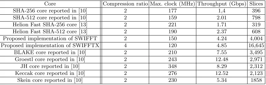
Compared to the leading commercial cores [13] and state-of-the-art imple-mentations of the SHA-256 and SHA-512 hash functions (which remain de-facto standards in the industry) [10], the proposed hardware implementation of the SWIFFT and SWIFFTX hash functions achieve a higher throughput due to pipelining. On the other hand, pipelining also has an impact on area require-ment - as given in Table 4, the SWIFFT and SWIFFTX hash functions are not as efficient regarding the resource utilization compared to the hardware implementation of other hashing algorithms. However, a remarkable aspect is that the implementation still fits in a single FPGA chip of medium size. Com-pared to the SHA-3 finalists, SWIFFT and SWIFFTX give a stronger security guarantee by proving that finding collisions in SWIFFT is at least as difficult as finding short vectors in ideal lattices. However, based on Table 4, it can be seen that this guarantee comes at a higher hardware cost.
Table 4. Comparison of the proposed hardware implementation of the SWIFFT and SWIFFTX hash function with published implementation of the SHA-2 and SHA-3 finalist hash functions
Core Compression ratio Max. clock (MHz) Throughput (Gbps) Slices SHA-256 core reported in [10] 2 177 1,4 396 SHA-512 core reported in [10] 2 159 2.01 798 Helion Fast SHA-256 core [13] 2 221 1.71 319 Helion Fast SHA-512 core [13] 2 190 2.37 608 Proposed implementation of SWIFFT 2 150 4.24 4,004 Proposed implementation of SWIFFTX 4 120 4.85 16,645
BLAKE core reported in [10] 2 210 7.55 3,495 Groestl core reported in [10] 2 243 12.48 2,971
JH core reported in [10] 2 348 8.29 2,312
Keccak core reported in [10] 2 276 12.52 2,123 Skein core reported in [10] 2 230 5.34 1858
7 Conclusion and Future Work
This paper presented a pipelined architecture for the FFT performed over Zp
chips) and achieve a significant speedup (more than one order of magnitude) compared to the SIMD software implementations reported in [22] and [4]. Com-pared to the hardware implementation of the SHA-256 and SHA-512 hash func-tions, the proposed implementation of SWIFFT and SWIFFTX obtain a higher throughput, though with increased area utilization. The throughput to area ra-tio of SWIFFT and SWIFFTX are below the rara-tio of the hardware implemen-tations for the SHA-3 finalist functions.
As mentioned in the introduction, the proposed implementations for SWIFFT and SWIFFTX are optimized for the concrete parameters proposed in [22] and are not scalable regarding area requirements. However, it should be pointed that our architecture can, up to minor modifications, accomodate slightly larger values of n, such as the last parameter set of Table 1 of [5], in order to reach larger levels of security: one just needs to use the decomposition of an FFT of size 2ninto two FFTs of sizen, at a cost of a factor of 2 loss in throughput. An increase ofmcan similarly be dealt with, up to a linear loss in throughput.
Our implementation choice however makes heavy use of the choicep= 257. One might think of exploring more generic or scalable architectures for the modular FFT. Since this modular FFT is the building block of all lattice-based primitives, this would be of great use for future work. We intend to continue in this direction in a forthcoming paper regarding Lyubashevsky’s signature scheme [20].
References
1. D. P. Agrawal and T. R. N. Rao. Modulo (2n+ 1) arithmetic logic. IEEE Journal on
Electronic Circuits and Systems, 2(6):186–188, 1978.
2. M. Ajtai. Generating Hard Instances of Lattice Problems (Extended Abstract). InSTOC, pages 99–108. ACM, 1996.
3. M. Ajtai. Generating Hard Instances of the Short Basis Problem. In Proceedings of the 1999 International Colloquium on Automata, Languages and Programming (ICALP 1999), volume 1644 ofLNCS, pages 1–9. Springer, 1999.
4. Y. Arbitman, G. Dogon, V. Lyubashevsky, D. Micciancio, C. Peikert, and A. Rosen. SWIFFTX: A Proposal for the SHA-3 Standard. Submission to NIST, 2008. Available at
http://www.eecs.harvard.edu/~alon/PAPERS/lattices/swifftx.pdf.
5. J. Buchmann and R. Lindner. Secure Parameters for SWIFFT. InINDOCRYPT, volume 5922 ofLecture Notes in Computer Science, pages 1–17. Springer, 2009.
6. J.W. Cooley and J.W. Tukey. An algorithm for the machine calculation of complex Fourier series. Mathematics of Computation, 19(90):297–301, 1965.
7. A. V. Curiger, H. Bonnenberg, and H. Kaeslin. Regular VLSI architectures for multipli-cation modulo (2n+ 1). IEEE Journal of Solid-State Circuits, 26(7):990–994, 1991. 8. ¨O. Dagdelen and M. Schneider. Parallel Enumeration of Shortest Lattice Vectors. In
Proc. of Euro-Par’ 2010, volume 6272 ofLNCS, pages 211–222. Springer, 2010.
9. J. Detrey, G. Hanrot, X. Pujol, and D. Stehl´e. Accelerating lattice reduction with FPGAs. InProc. of LATINCRYPT, volume 6212 ofLNCS, pages 124–143. Springer, 2010. 10. K. Gaj, E. Homsirikamol, M. Rogawski, R. Shahid, and M. U. Sharif. Comprehensive
evaluation of high-speed and medium-speed implementations of five SHA-3 finalists using Xilinx and Altera FPGAs. 3rd SHA-3 candidate conference, Mar 2012.
11. N. Gama and Phong Q. Nguyen. Predicting Lattice Reduction. In Proc of Eurocrypt 2010, volume 6110 ofLNCS, pages 31–51. Springer.
13. Helion, Cambridge, UK,http://heliontech.com/fast_hash.htm.Fast Hash Core Fam-ily for Xilinx FPGA.
14. J. Hermans, M. Schneider, J. Buchmann, F. Vercauteren, and B. Preneel. Parallel Shortest Lattice Vector Enumeration on Graphics Cards. In Proc. of AfricaCrypt 2010, volume 6055 ofLNCS, pages 52–68. Springer.
15. J. Hermans, F. Vercauteren, and B. Preneel. Speed Records for NTRU. In Proc. of CT-RSA 2010, pages 73–88, 2010.
16. J. Hoffstein, J. Pipher, and J. H. Silverman. NTRU: A Ring-Based Public Key Cryp-tosystem. InProc. of ANTS 3, pages 267–288, 1998.
17. W. R. Knight and R. Kaiser. A Simple Fixed-Point Error Bound for the Fast Fourier Transform. IEEE Trans. on Acoust., Speech, Signal Processing, 27(6):615–620, 1979. 18. P-C. Kuo, M. Schneider, ¨O. Dagdelen, J. Reichelt, J. Buchmann, C-M. Cheng, and B-Y.
Yang. Extreme Enumeration on GPU and in Clouds. In Proc. of CHES’2011, volume 6917 ofLNCS, pages 176–191. Springer, 2011.
19. R. Lindner and C. Peikert. Better key sizes (and attacks) for LWE-based encryption. In
Proc. of CT-RSA 2011, volume 6558 ofLNCS, pages 319–339. Springer.
20. V. Lyubashevsky. Lattice signatures without trapdoors. In Proc. of Eurocrypt 2012, volume 7237 ofLNCS, pages 738–755. Springer, 2012.
21. V. Lyubashevsky and D. Micciancio. Generalized Compact Knapsacks Are Collision Re-sistant. InProc. ICALP (2), volume 4052 ofLNCS, pages 144–155. Springer, 2006. 22. V. Lyubashevsky, D. Micciancio, C. Peikert, and A. Rosen. SWIFFT: a modest proposal
for FFT hashing. In K. Nyberg, editor, Fast Software Encryption – FSE 2008, number 5086 in Lecture Notes in Computer Science, pages 54–72. Springer, 2008.
23. V. Lyubashevsky, C. Peikert, and O. Regev. On ideal lattices and learning with errors over rings. InProc. of EUROCRYPT, volume 6110 ofLNCS, pages 1–23. Springer, 2010. 24. U. Meyer-Baese.Digital Signal Processing with Field Programmable Gate Arrays (Signals and Communication Technology). Springer-Verlag New York, Inc., Secaucus, NJ, USA, 2004.
25. D. Micciancio and O. Regev. Lattice-Based Cryptography. InPost-Quantum Cryptogra-phy, D. J. Bernstein, J. Buchmann, E. Dahmen (Eds), pages 147–191. Springer, 2009. 26. M. Naehrig, K. Lauter, and V. Vaikuntanathan. Can homomorphic encryption be
prac-tical? InProc. of CCSW, pages 113–124. ACM, 2011.
27. C. Peikert and A. Rosen. Efficient Collision-Resistant Hashing from Worst-Case Assump-tions on Cyclic Lattices. In Proc. TCC 2006, volume 3876 of LNCS, pages 145–166. Springer, 2006.
28. A. Peled and B. Liu. A New Hardware Realization of Digital Filters. IEEE Trans. on Acoust., Speech, Signal Processing, 22:456–474, 1974.
29. J. M. Pollard. The Fast Fourier Transform in a finite field.Mathematics of Computation, 25(114):365–374, 1971.
30. O. Regev. On lattices, learning with errors, random linear codes, and cryptography. In
Proc. of STOC, pages 84–93. ACM, 2005.
31. O. Regev. On lattices, learning with errors, random linear codes, and cryptography. J. ACM, 56(6), 2009.
32. N. P. Smart and F. Vercauteren. Fully Homomorphic Encryption with Relatively Small Key and Ciphertext Sizes. InPublic Key Cryptography, volume 6056 ofLecture Notes in Computer Science, pages 420–443. Springer, 2010.
33. S. A. White. Applications of Distributed Arithmetic to Digital Signal Processing. IEEE ASSP Magazine, 6(3):4–19, 1989.
34. Xilinx Inc.,http://www.xilinx.com/support/documentation/user_guides/ug193.pdf.
Virtex-5 FPGA XtremeDSP Design Considerations.