C
o m p u t i n g
S
u r f a c e
CS-2 Hardware Overview
1.
Hardware Overview . . . .
1
CS-2 Bays . . . 2
CS-2 Modules . . . 3
Processor Boards. . . 4
Network Switch Boards . . . 5
I/O Devices . . . 5
The CS-2 Data Network . . . 6
1
Hardware Overview
1
The CS-2 consists of the following key hardware components:
•
The Bay.•
The Modules.•
Processor Boards.•
Network Switch Boards.•
I/O Devices•
The CS-2 data network.•
The CS-2 control and diagnostic network.2 S1002–10M141.00
1
CS-2 Bays
The Bay provides the physical infrastructure for the modules; it provides the power distribution, cabling for the data and control networks, ducting to maxim-ise the flow of cooling air through the modules, and a firm and level securing point for the modules.
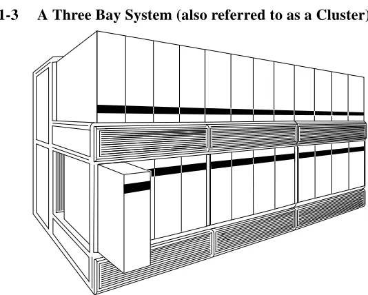
The Bay is a scalable tubular structure which can be adapted to suit a number of machine configurations, from the 4 module Half Bay system to the 24 module 3-Bay system. Larger systems are configured as a number of interconnected bays.
Figure 1-1 A Half Bay System
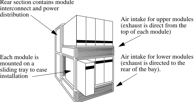
Figure 1-2 A Single Bay System
Rear section contains module interconnect and power distribution
Air intake for upper modules (exhaust is direct from the top of each module)
Air intake for lower modules (exhaust is directed to the Each module is
mounted on a sliding tray to ease installation
Hardware Overview 3
1
Figure 1-3 A Three Bay System (also referred to as a Cluster)
CS-2 Modules
There are currently three types of module that can be fitted into a Bay: the Proc-essor Module, containing procProc-essor boards and a number of SCSI disk devices, the Switch Module, containing switching components for the CS-2 data network, and the Peripheral Module, which contains an array of SCSI disk devices.
All modules include cooling fans, power supplies, and a dedicated module con-troller processor which is the module’s interface to the CS-2 control and diagnos-tics network. A printed circuit board within each module — the module’s backplane board — distributes the power and control signals to the module’s contents, and also carries the data buses to the module’s rear connectors. Most connections from the module to the Bay are via Beta Flex connections which are fixed to the Bay at each module’s mounting position; these are zero insertion force connectors that open and close (thus gripping the module’s connections) under the control of an electric current.
More information about the modules can be found in:
Hardware Overview 7
1
•
The Communications Network Overview, document S1002–10M105.The Control and Diagnostics Network
The control and diagnostic network is a hierarchical, low bandwidth serial net-work that runs throughout the system. All modules, boards, and processors have an interface to this network.
The control network carries heartbeat signals from all components (to signal con-tinued operation) and is also used by system software, such as the machine man-ager and Pandora, to query the operating status of system components, and to reset or reconfigure those components. Remote console connections to the SPARC processors can also be carried over the control network.
The control network is independent of the data network and does not impact on its performance.
The control network is described in the following Meiko document:
8 S1002–10M141.00