CSEIT184505 | Published - 14 April 2018 | March-April-2018 [ (4 ) 5 : 41-49]
40
Tensile and Impact Properties Evaluation of Eutectic,
Hypereutectic and Special Eutectic Aluminium Alloys under
Various Heat Treated Conditions By Experimental Approach
K. A. Jayasheel Kumar1, Dr. C. M Ramesha2
1Assistant Professor, Dept of Automobile Engg, New Horizon College of Engg, Bengaluru, Karnataka, India
2Associate Professor, Dept. of Mechanical Engg., M.S.Ramaiah Institute of Technology, Bengaluru , Karnataka, India
ABSTRACT
The study deals with the evaluation of tensile properties of eutectic, hypereutectic and super eutectic aluminium alloy under various heat treated conditions. Pistons are produced from cast or forged, high-temperature resistant aluminium silicon alloys. There are three basic types of aluminium piston alloys. The standard piston alloy is a eutectic Al-12%Si alloy containing in addition approx. 1% each of Cu, Ni and Mg. Special eutectic alloys are also evaluated for improved strength at high temperatures. Hypereutectic alloys with 18 and 24% Si provide lower thermal expansion and wear, but have lower strength. The tensile and impact properties are evaluated for all the conditions of eutectic, hypereutectic and special eutectic aluminium alloys. The experimentation is carried on a bench tensometer and on Izod and Charpy Impact testing machine. The properties are evaluated for various heat treated conditions like operating temperature, quenching conditions, annealing conditions. It is concluded that based on the impact and tensile properties, type of material can be selected as the piston material.
Keywords : Eutectic, Hypereutectic and Special Eutectic Al Alloy, Heat treated, Wear properties
INTRODUCTION
CSEIT184505 | Published - 14 April 2018 | March-April-2018 [ (4 ) 5 : 41-49]
41 Al2O3 fibre reinforced bottoms are produced by squeeze casting and used mainly in direct injection diesel engines. The main advantage, apart from a general improvement of the mechanical properties, is an improvement of the wear behaviour [5].
Depending on the silicon concentration in the alloy and the cooling conditions, the structure of the casting will essentially comprise mixtures of aluminium grains, silicon crystals and aluminium silicon eutectic as well as various intermetallic phases formed from other alloying additions (Mg2Si, CuAl2). The aluminium grains can grow very large however, under slow cooling conditions, such as in sand castings or heavy sections, and this can lead to poor casting and mechanical properties.
The system Al-Si alloy
Among commercial aluminium casting alloys those with silicon as the major alloying element are the most important, mainly because of their excellent casting characteristics. Additions of Si to pure aluminium impart high fluidity, good feeding characteristics, low shrinkage and good hot cracking resistance [1]. The properties of aluminium-silicon alloys make them very popular in various applications including the automotive, aerospace and defence industries. The high strength to weight ratio is one of their most interesting characteristics [2].
As the density of Si is 2.3 g/cm3, it is one of the few elements which may be added to aluminium (2.7 g/cm3) without loss of weight advantage [3]. Aluminium-silicon alloys that do not contain copper additions are used when good cast ability and good corrosion resistance are needed. Magnesium can act as a substitute for copper. Magnesium and silicon can form the intermetallic hardening phase Mg2Si which precipitates in the α-aluminium matrix and increases the yield strength [4].
Fig.1-Equilibrium binary Al-Si phase diagram
CSEIT184505 | Published - 14 April 2018 | March-April-2018 [ (4 ) 5 : 41-49]
42 is an important distinction between mechanical wear compared to other processes with similar out come [5].
Additionally, most modern pistons contain a large amount of silicon. Silicon is added to the aluminum because the resulting alloy is more resistant to wear and expansion than an alloy that doesn't contain silicon.
Heat Treatment is often associated with increasing the strength of material, but it can also be used to alter certain manufacturability objectives such as improve machining, improve formability, restore ductility after a cold working operation. Thus it is a very enabling manufacturing process that can not only help other manufacturing process, but can also improve product performance by increasing strength or other desirable characteristics. [6][7]
The specific amount of silicon added to the aluminum ranges from 9-18%. At percentages below 12%, whatever silicon that is added to the aluminum dissolves into the solution. Once you reach 12% (or thereabouts), the aluminum alloy become saturated with silicon. This specific point is called the saturation point, and any silicon added after the saturation point will not dissolve in the finally aluminum alloy [8]. Instead, this excess silicon will form a hard precipitate that remains separate from the aluminum.
An aluminum alloy that is sutured with silicon is known as "eutectic." When the alloy contains silicon at a percentage that is less than saturated, it's called "hypoeutectic." When the alloy contains more silicon that then saturation limit, it's called "hypereutectic."
The characteristics of pistons in each of these categories are very distinct. Hypereutectic alloys are stronger, resist scuffing and seizure, and reduce groove wear and cracking of the crown at extremely high temperatures. They're also very resistant to expansion, because the high percentage of silicon essentially "insulates" the piston from the effects of heat.
Hypereutectic designs also allow for decreased distance between ring grooves, which improve the "seal" between the rings and the cylinder wall and improves efficiency. Finally, because hypereutectic pistons don't expand or contract, they're ideal for modern engines with tight clearance requirements. Generally speaking, modern engines use pistons made from a hypereutectic aluminum alloy.
If there is a downsides to hypereutectic pistons, it's that they're brittle compared to forged pistons. Therefore, forged pistons are more forgiving of extreme conditions (like those found in a race car), and they give you a greater margin of error when dealing with timing problems, as detonation is less likely to destroy a forged piston than a hypereutectic cast piston.
CSEIT184505 | Published - 14 April 2018 | March-April-2018 [ (4 ) 5 : 41-49]
CSEIT184505 | Published - 14 April 2018 | March-April-2018 [ (4 ) 5 : 41-49]
44 Table-2 Mechanical properties of piston alloys
EXPERIMENTAL DETAILS
Tensile Test
A tensile test also known as tension test is the fundamental type of mechanical test that can be performed on material [18]. The specimen is subjected to a continuously increasing tensile force while simultaneous observation is made on the elongation of the specimen. The maximum conventional stress that can be sustained by a material is called tensile strength.
CSEIT184505 | Published - 14 April 2018 | March-April-2018 [ (4 ) 5 : 41-49]
45 Fig.2 Bench Tensometer
11
10
10
11
32
26
Fig.3 Tensile specimen Impact Test
Impact test is a standardized high strain rate test which determines the amount of energy absorbed by a material during fracture. The absorbed energy is a measure of a given material toughness and acts as a tool to study temperature depended brittle-ductile transition. It is widely applied in industry, since it is easy to prepare and conduct, and hence results can be obtained quickly and cheaply. But the major disadvantage is that all results are only comparative.
Impact resistance is one of the most important properties for a part designer to consider, and without question, and the most difficult to quantify. The impact resistance of a part is into many applications, a critical measure of a service life.
Types of impact tests
The two basic impact tests are: 1. Izod (Cantilever) Test 2. Charpy (Beam) Test Izod (Cantilever) Test
CSEIT184505 | Published - 14 April 2018 | March-April-2018 [ (4 ) 5 : 41-49]
46 Charpy (Beam) Test
The charpy test is also known as charpy V-notchtes, is standard high strain rate test which determines the amount of energy absorbed by a material during fracture. This absorbed energy is a measure of given material’s toughness and acts a tool to study temperature -dependent brittle- ductile transition. It is widely applied in industry, since it is to prepare and conduct and results can be obtained quickly and cheaply. But a major disadvantage s that all results are only comparative.
The test was developed in 1905 by the French scientist Georges Charpy. It was pivotal in understanding the fracture problem of ship during the Second World War. It is used in many industries for testing and building construction materials used in the construction of pressure vessels bridges and to see how storms will affect materials used in buildings. Figure 4shows the Charpy Impact tester. Figure 5 shows the impact specimen.
The specimens of the required dimensions are prepared as per ASTM standards and a V-notch is made in the center. The specimen is placed on the Charpy impact tester. The pendulum is made to fall from the required height and the specimen is fractured. The angle of pendulum travel is noted down. The impact strength is calculated.
Fig.4 Charpy Impact tester
CSEIT184505 | Published - 14 April 2018 | March-April-2018 [ (4 ) 5 : 41-49]
47 RESULTS AND DISCUSSION
The tensile test is carried out on a bench Tensometer. The specimens are loaded onto the Tensometer. Firstly the elongation gauge used to measure the percentage elongation was set according to the gauge length of the specimen.
Before pulling the test piece, it is laid in the cradle, the pivoted arm is moved to the left slide before the arm reading is zero. The left slide is then locked.
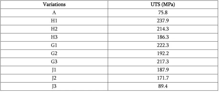
The specimen is held using specified shackles and the test is conducted until failure of the specimen. The load reading is noted down from the scale. Figure 6 shows the graph of ultimate tensile strength. Table 3 shows the UTS values. As the solution temperature is increased above the saturated solution temperature, the material losses its ductility, hence the UTS values decreases as the temperature variation is carried out and also decreases as aging time is varied and also same as in the case of quenchant variation.
Table 3 The Ultimate Tensile Strength
Variations UTS (MPa)
A 75.8
H1 237.9
H2 214.3
H3 186.3
G1 222.3
G2 192.2
G3 217.3
J1 187.9
J2 171.7
J3 89.4
CSEIT184505 | Published - 14 April 2018 | March-April-2018 [ (4 ) 5 : 41-49]
Fig.6 Graph of ultimate tensile strength of AA 7075 alloy
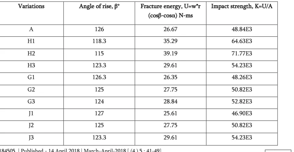
The impact test was carried out using Charpy Test. The pendulum is lifted to its upper position, and the pointer is made to touch the pendulum. The initial reading is set to zero. The specimen is mounted on the anvil using the template with the notch facing away from the striker edge of the pendulum. The specimen is fractured by the releasing of pendulum. Table 4 shows the values of fracture energy and impact strength.
Length of the pendulum – r- 0.825ms Angle of fall - α- 160°
Weight of the pendulum - w- 91.875N
Impact velocity – sqrt (2*g*r (1- cos (160))) - 6.169m/s Area – 96mm2
Table 4 The values of fracture energy and impact strength Variations Angle of rise, β° Fracture energy, U=w*r
CSEIT184505 | Published - 14 April 2018 | March-April-2018 [ (4 ) 5 : 41-49]
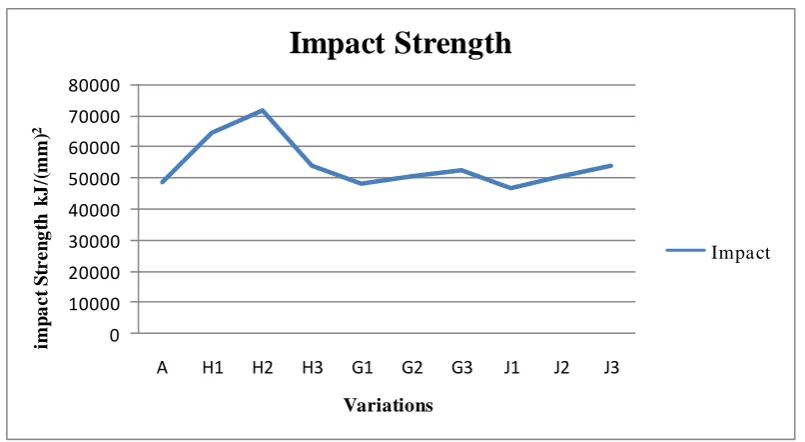
49 As the solution temperature is increased above the saturated solution temperature, the material losses its ductility, hence the impact strength values decreases as the temperature variation is carried out and increases as the aging time is varied and also same as in the case of quenchant variation.
Figure 7 shows the graph of impact strength of AA 7075 alloy.
0
Fig.7 Graph of impact strength of AA 7075 alloy
REFERENCES
[1] “Properties and Selection: Non ferrous Alloys and Special-Purpose Materials”, 1990, ASM Hand Book, Vol.2, Tenth Edition, pp 39-40.
[2] “Properties and Selection: Non ferrous Alloys and Special-Purpose Materials”, 1990, ASM Hand Book, Vol.2, Tenth Edition, pp 511-514.
[3] L.F.Mondolfo, “Aluminium alloys structure and properties,” First publication 1979
[4] K. Srinivasulu Reddy, G. Ranga Janardhana, “Developing a neuro fuzzy model to predict the properties of Al-Si12 alloy,” vol. 4, no. 10, december 2009
[5] Shivanath R, Sengupta PK, Eyre TS, “Wear of aluminium–silicon alloy”, Br Foundrymen 1977; 79:349–56.
[6] ASM heat treating hand book, Vol.4- Heat treatment of non- ferrous alloys, ASM international, 1991, pp 842-879.
[7] Metals hand book, Vol.8- Mechanical testing: ASM international 10th edition. 1990, pp 20, 74-75
[8] J. Gilbert Kaufman, FASM, Properties of aluminium alloys, ASM international 3rd edition, 2002, pp 206-217.