ISSN (Print) : 2347 - 6710
I
nternationalJ
ournal ofI
nnovativeR
esearch inS
cience,E
ngineering andT
echnologyVolume 3, Special Issue 3, March 2014
2014 International Conference on Innovations in Engineering and Technology (ICIET’14) On 21st & 22nd March Organized by
K.L.N. College of Engineering, Madurai, Tamil Nadu, India
ABSTRACT— In this project, the auxiliary switch control using a lookup table using FO-PID is proposed to enhance the efficiency of the bidirectional DC/DC converter used in electric vehicle, which performs soft switching. Continuous current data are difficult to obtain during a resonant operation due to the limit of ADC capacity. The control method properly controls the auxiliary switch turn-on time according to the required load current; this auxiliary switch control brings the more efficient control in generative and regenerative mode operation. This work proposed a design methodology of auto-adjustable PI controller using Artificial Intelligent controller technique. The proposed AI method can adjust the controller parameters in response to changes in plant and disturbance that specifies properties of the desired control system. In order to analyze the performances of the proposed system using PI controller tuned with Improved Particle Swarm Optimization algorithms. The work has been implemented with MATLAB / Simulink 7.13 software environment.
INDEX TERMS- Fractional Order Proportional Integral Derivative, Improved particle swarm optimization, soft switching, bidirectional converter, auxiliary switch control.
I. INTRODUCTION
The environmental and economical benefits from commercial electric vehicles have stimulated global interest in developing electric vehicles. To improve the efficiency of electric vehicles, the auto industry has financially invested significantly in batteries, various types of charging equipment’s, inverters and bidirectional dc/dc converters, and traction motors for EVs. Among them, various topologies for the bidirectional dc/dc converter have been proposed for many EVs [1]–[10]. The bidirectional dc/dc converter on board electric and hybrid vehicles should boost the low voltage of batteries to the high voltage of the inverter dc-link [4]. It should
bank with regenerative energy during vehicle deceleration and braking. The importance of a bidirectional dc–dc converter is getting increased. Because the structure of the converter is simple, and its control is comparably easy, it is used as the topology of conventional bidirectional converter. However, the drawbacks of the conventional bidirectional dc–dc converter are the large switching losses and the long reverse recovery time of antiparallel diodes. Particularly, during the reverse recovery time of the diodes, it can be caused of circuit damage and electromagnetic interference problems due to high current spikes. Thus, in order to improve the shortcomings of conventional pulse width modulation (PWM) methods, and increase the efficiency of the system, the study using series resonance, parallel resonance, and quasi-resonance methods have progressed [11], [12]. However, due to the common characteristic of resonant converter, lots of conduction losses occur because of high circulating energy. To overcome the drawbacks of the resonant converter, the zero voltage transition (ZVT) and zero current transition (ZCT) methods are proposed [13]–[16]. The ZVT and ZCT methods are that switches turning ON and turning OFF under zero voltage and zero current condition using resonance. The ZVT and ZCT methods can be applied to the conventional bidirectional dc–dc converter through adding auxiliary circuit to the converters. However, since the added auxiliary circuit is operated under hard-switching condition, the other losses occur [13]. Moreover, lots of other circuits are weak in high resonant current and voltage, and the range of load for resonant circuit is limited. The composition of the proposed resonant bidirectional dc/dc converter is an auxiliary circuit added form to the conventional bidirectional buck–boost converter. The fundamental operation equals the conventional bidirectional buck– boost converter [18]–[20]. The resonance of the proposed converter is caused by the resonant capacitor and inductor of the auxiliary circuit. The auxiliary switch is operated in boost mode and buck mode. The soft switching is carried out by the main switches, diodes, and auxiliary switches.
Fractional Order PID Controller Based
Bidirectional Dc/Dc Converter
K.Giridharan
#1,A.Karthikeyan
*2#1 PG Scholar, M.E. – Power Electronics & Drive, PSNA College of Engineering & Technology, Dindigul,
India.
To perform the soft-switching action, the conventional control method has to calculate the time difference between the gate signals of the main and auxiliary switches. The aim of this work is to introduce the auxiliary switch turn-on time control for the bidirectional dc/dc converter in an electric vehicle system.
II. OPERATION AND ANALYSIS OF THE PROPOSED CONVERTER
A.PROPOSED CONVERTER CONFIGURATION
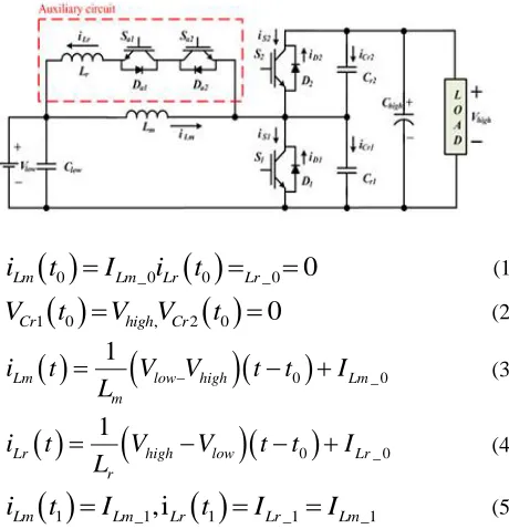
Fig. 2.1 shows the proposed bidirectional soft-switching dc–dc converter, which is formed by adding one resonant inductor, two resonant capacitors, and two switches to the conventional bidirectional converter circuit. The soft-switching operation occurred by energizing Lr in the auxiliary circuit with the voltage difference Vhigh−Vlow just before turning ON the main switch. In order to maintain the voltage across Lr with Vhigh−Vlow before the main switch is turned ON, the upper converter should be operated in continuous conduction mode.
OPERATION MODE:
MODE 1 (t0≤t<t1):At t=t0, both switches S1and Sa1are in turn-off state. When the Sa1is turned ON, mode 1 is started. Since the resonance of Lr, any current is not flowing through Sa1, and the switch is turned ON under the ZCT condition. During this mode, iLr is increased by the current flowing through Lm and the antiparallel diode of Sa2, and it can be described as (1)–(5). When the same amount of current is flowing though Lm and Lr, this mode is finished.
Fig .1. Proposed soft switching directional dc/dc converter
0 _0
0 _00
Lm Lm Lr Lr
i
t
I
i
t
(1)
1 0 , 2 0
0
Cr high Cr
V
t
V
V
t
(2)
0
_ 01
Lm low high Lm
m
i
t
V
V
t
t
I
L
(3)
0
_ 01
Lr high low Lr
r
i
t
V
V
t
t
I
L
(4)
1 _1,i
1 _1 _1Lm Lm Lr Lr Lm
i
t
I
t
I
I
(5)MODE 2 (t1≤t<t2): When iLr is larger than iLm, mode 2 begins. Due to the continuity of iLr, the resonance
between S1 and the output capacitor of S2 is started. Two switches S1 and S2 are in turn-off state, and as the capacitor Cr1 is charged and discharged iLm and resonant capacitor current flow through Lr. As a result, the voltage across S1 and S2 is decreased and increased complementary due to the resonance. It can be described through (7). When the voltage acrossS1 becomes 0V, and that of S2 is equal to Vhigh, the resonance between Cr1and Lr is finished. Moreover, iLr is getting decreased.
1 _1 _1Lr Lr Lm
i
t
I
I
(6)
1 _1 _ 2Lm Lm Lm
i
t
I
I
(7)
sin
1
_1high low
Lr r Lr
r
V
V
i
t
t t
I
Z
(8)
1
cos
1Cr low high low r
V
t
V
V
V
t t
(9)
2 1
Cr high Cr
V
t
V
V
t
(10)1 2
r r r
C
C
C
(11)1
, Z
rr r
r r r
L
C
L C
(12)MODE 3 (t2 ≤t <t3): Even though the iLr is getting decreased from mode 2, since the amount of iLr is still larger than that of Lm, the continuity of current is maintained. Thus, the surplus iLr is flowing through the antiparallel diode of S1. Since the surplus current is flowing through the antiparallel diode of S1, the voltage across S1 is equal to zero, and the switch can be turned ON under the ZVT condition. In this mode, iLr and iLm are depicted with following equations, and when the same amount of current is flowing through those two inductors, Lm and Lr, mode 3 is finished
2
_ 21
Lm low Lm
m
i
t
V
t
t
I
L
(13)
2
_ 21
Lr low Lr
r
i
t
V
t
t
I
L
(14)
3 _3 _3Lr Lr Lm
i
t
I
I
(15)MODE 4 (t3≤t<t4): At the beginning of this mode, the main switch S1 is turned ON under the ZVT condition. As the main inductor current is increased linearly, the main switch current is increased as well. At the end of this mode, the resonant inductor is discharged completely and the current of the auxiliary switch becomes 0 A
3
_ 31
Lm low Lm
m
i
t
V
t
t
I
L
(16)
3
_ 31
Lr low Lr
r
i
t
V
t
t
I
L
MODE 5 (t4≤t<t5): Since any current is not flowing through Sa1, the current loop is exactly same as that of the conventional bidirectional dc–dc converter in boost mode. That is, the main inductor current is flowing through S1, and the main inductor current is increased. When t=t5, S1 is turned OFF under the ZVT condition due to the resonance of Cr1, and the auxiliary switchSa1 is turned OFF under the ZCT condition. When the two switches are turned OFF, this mode is finished
40
Lr
i
t
(18)
4
_ 41
Lm low Lm
m
i
t
V
t
t
I
L
(19)MODE 6 (t5 ≤t<t6): In mode 6, the main inductor current is flowing through S1,Cr1 consistently. The voltage acrossS1 is increased meanwhile the voltage acrossS2 is decreased, and the equations are given. When the voltage acrossS1 is equal to output voltage,S2is turned ON under the ZVT condition. Note that Cr means Cr1+Cr2 as (11), and the parameter of these two capacitors should be almost same for correct ZVT condition
_5 _6Lm Lm Lm
i
t
I
I
(20)
0
Lri
t
(21)
1
5
1
tCr Lm
r t
V
t
i
t dt
C
(22)
2
5
1
tCr high Lm
r t
V
t
V
i
t dt
C
(23)MODE 7 (t6 ≤t <t7): When the antiparallel diode of S2 is conducted, mode 7 is started. The main inductor current is decreased until Sa1 is turned ON, and it can be described as (24). When current is flowing through the antiparallel diode of S2, the ZVT turning-on and ZVT turning-off conditions are qualified. Moreover, since the current flows through the antiparallel diode of S2, the current path is secured, and loss is reduced. That is, the turning-on loss of the diode is larger than that of RDS (ON) conduction loss.
6
_ 61
Lm low high Lm
m
i
t
V
V
t
t
I
L
(24)
7 _7 _0Lm Lm Lm
i
t
I
I
(25)TABLE1
BIDIRECTIONAL DC/DC CONVERTER PARAMETERS
PARAMETER SYMBOL VALUE UNIT
Input Voltage
low
V
100 VOutput Voltage
high
V
200 VRated Power
0
P
10 KWMain inductor
m
L
1.5 mHResonant
Inductor
L
r5 H
Resonant
Capacitor
C
r1,
C
r220 nF
Output Capacitor
out
C
2390 FSwitching
Frequency
F
SW20 KHZ
III.CONTROL TECHNIQUES FOR DC-DCCONVERTERS
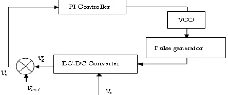
Due to the time varying and switching, PI controller is a well known controller which is used in the most application. PI controller becomes a most popular industrial controller due to its simplicity and the ability to tune a few parameters automatically. The classical control methods employed to design the controllers for DC-DC Converters depend on the operating point so that the presence of parasitic elements, time-varying loads and variable supply voltages can make the selection of the control parameters difficult. Conventional controllers require a good knowledge of the system and accurate tuning in order to obtain the desired performances.
PI Controller:
Fig.2.Structure of PI controller
PI most widely-used type of controller for industrial applications and exhibit robust performance over a wide range of operating conditions. The parameters involved are Proportional (P) and Integral (I).Fig.3.1 show the basic structure of PI controller. The proportional part is responsible for following the desired set-point, while the integral part account for the accumulation of past errors and the rate of change of error in the process respectively. In spite of simplicity, they can be used to solve even a very complex control problem, especially when combined with different functional blocks, filters (compensators or correction blocks), selectors etc.
Fig.3.Block diagram of PI control for DC-DC Converter
(Vref) is the Reference Voltage, supply voltage (Vs), (Ve) is the error voltage, output voltage(Vo)
A continuous development of new control algorithms insure that the PID controller has not become obsolete and that this basic control algorithm will have its part to play in foreseeable future. It can be expected that it will be a backbone of many complex control systems. While proportional and integral modes are also used as single control modes, a derivative mode is rarely used in control systems. PI controller algorithms are mostly used in feedback loops. PI controllers can be implemented in many forms. It can be implemented as a stand-alone controller or as part of Direct Digital Control (DDC) package or even Distributed Control System (DCS). In proportional control,
P
P t
K e t
(26) Proportional action, p(t), where the signal is proportional to the error signal at the present moment.In Integral control,
0
( )
t ii t
K e t dt
(27)Integral action, i(t), where the signal is proportional to the commutative values of the error signal up to the present moment. where Kp, Ki and Kd are constants.
The overall control action, m(t), can be expressed as:
0
( )
t
P i
m t
K e t
K e t dt
(28)In the s-domain, this can be expressed as:
I
P
K
M s
K
E s
S
(29)As Kp is increased, the system speed increases (with a tendency to overshoot), and the steady state error decreases, but is not eliminated. As Kd is increased, the damping factor increases, thereby reducing the overshoot. The derivative control is susceptible to noise and it is never used alone. As Ki is increased, the steady-state error goes to zero and the system tends towards instability. Integral control is also never used alone. Fig.3 show the block diagram of PI control for DC-DC Converter
IV.FRACTIONAL ORDER PID CONTROLLER
The most common form of a fractional order PID controller is the PIλDμ controller (Podlubny, 1999a), involving an integrator of order λ and a differentiator of order μ where λ and μ can be any real numbers. The transfer function of such a controller has the form
1
,
,
0
C P I D
U s
G
s
K
K
K S
E s
S
(30)Where Gc(s) is the transfer function of the controller, E(s) is an error, and U(s) is controller’s output. The integrator term is 1 sλ, that is to say, on a semilogarithmic plane, there is a line having slope -20λdB/decade. The control signal u(t)can then be expressed in the time domain as
P
I
D
U t
K e t
K D e t
K D e t
(31)Fig. 4 is a block-diagram configuration of FOPID. Clearly, selecting λ = 1 and μ = 1, a classical PID controller can be recovered. The selections of λ = 1, μ = 0, and λ = 0, μ = 1 respectively corresponds conventional PI & PD controllers. All these classical types of PID controllers are the special cases of the fractional PIλDμ controller .
It can be expected that the PIλDμ controller may enhance the systems control performance. One of the most important advantages of the PIλDμ controller is the better control of dynamical systems, which are described by fractional order mathematical models. Another advantage lies in the fact that the PIλDμ controllers are less sensitive to changes of parameters of a controlled system. This is due to the two extra degrees of freedom to better adjust the dynamical properties of a fractional order control system. However, all these claimed benefits were not systematically demonstrated in the literature.
V.IMPROVED PARTICLE SWARM OPTIMIZATION ALGORITHM
To enhance the refined pinpointing search ability and to strike a balance between exploration and exploitation of available PSOs, the following improvements are proposed
Velocity Updating:
Since the two random parameters r1 and r2 are independently generated, inevitably there are cases in which they are both too large and too small. In the former, both the personal and social experiences accumulated so far are overused and the particle might be driven away from the local optimum. For the latter case, both the personal and social experiences are not fully used, so the particle might not be able to find the local optimum. Therefore, the convergence performance of the algorithm is undermined. In other words, the two random weighting parameters reflecting the experiences of his own and his companions are not completely independent. By modelling this reasoning ability into an updating formula and noting the sum of the two inter-related weighting parameters can be set to 1, one singlerandom parameter that includes the cognitive and social experiences of the particle for updating its velocity is proposed. Therefore, the velocity is updated by using
1
1 1
1
1 1
ti i i i i
V t WV t c r P t X t c r g X t
(32) It should be noted that the communication between different particles in the proposed search procedure is set up in a hierarchical manner rather than a hierarchical manner.
Exceeding Boundary Control:
In updating the position of particles using (32),it is very common to find the coordinates of the new particles lying outside the boundaries of the parameter space. In such cases, the popular approaches used in available PSO algorithms are either to take the boundaries as the coordinates of the new particles, or to keep the coordinates of the particle unchanged but to assign the particle with an extremely poor objective function value. However, either treatment will reduce the diversity of the particles in the searching process and reduce the global search ability of the algorithm correspondingly. Therefore, in the improved PSO algorithm, a different approach is proposed in that if a new particle moves
outside the boundaries, the current velocity of the particle in question is modified using
d
.
vi T new
vi T
D
where d - distance between the particle and its violation boundary,
D -variation range.
It is obvious that the velocity is determined by the violation distance, the variation range and the previous velocity. Then, it can improve the diversity of the particles in the searching process and the global search ability of the algorithm to some extent.
Global Best Perturbation:
The particle swarm optimization (PSO) algorithm has been shown to converge rapidly during the initial stages of a global search, but around global optimum, the search will become very slow. For that reason, the global best perturbation operator is defined as follows: the global best can be expressed as:
1...
...pn
pg
p
pk
(34)
Where,
max min max min
min max
max
,
,min
,
2
2
k k k k
k k
p
p
p
p
pk
pk
p
pk
p
(35) pkmax, pkmin are upper and lower bounds of pk
respectively, µ is the perturbation parameter, which decreases with the increase of iterations.
VI.SIMULATION MODELS
In this chapter, the simulation results for DC-DC converter system using PI and FO-PID have been presented using Improved Particle Swarm Optimization Techniques. The servo and regulatory responses of the proposed system has been carried out. The responses are shown from Simulation work is carried in MATLAB 7.13/Simulink.
MATLAB / SIMULINK:
MATLAB / SIMULINK is one of the most successful software packages currently available. It is a powerful, comprehensive and user friendly software for simulation studies. Especially, functions are then interconnected to form a SIMULINK block diagram that defines the system structure.
Fig.5.MATLAB/Simulink model for proposed DC/DC Converter
Fig.6.MATLAB/Simulink Model for FO-PID Controller for Proposed DC/DC Converter
MATLAB SIMULATION RESULTS:
Fractional Order PID controller Response:
Fig 7. Simulated Voltage and Current Response of Proposed DC/DC Converter with set value of 200
Volts
Fig 8.Simulated Voltage and Current Response of S1 for ZVS switching of Proposed DC/DC Converter with
set value of 200 Volts
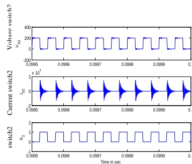
Fig 9.Simulated Voltage and Current Response of S2 for ZVS switching of Proposed DC/DC Converter with set
value of 200 Volts
VII.CONCLUSION
A method for tuning of PI and fractional order PID controller tuning using Artificial intelligence is proposed. The presented method is based determination of Kp , Ki and Kd for the conventional PI Controller. Similarly Kp , Ki, Kd, λ and μ is found by using IPSO. The simulation results that demonstrate that controller has better response compare with the PI and FO-PID controller using tuning of AI techniques from the observation. The PI and FO-PID controller is tuned with IPSO. The IPSO based Fractional order PID controller has the best response compared with the performance of the other controllers and tuning method mentioned above.
REFERENCES
[1] J.G. Zeigler and N.B. Nichols,” Optimum setting for automatic controller’, ASME Trans., pp. 759-768, 1942
[2] S.Manabe, “The non – integer integral and its application to control systems,” ETJ of Japan, vol.6, no.3-4, pp.83-87, 1961.4.
[3] K.J.Astrom, CC.Hang, P.Pearson and W.K Ho:” A self-tuning controller with PID structure.” Inst.J.of Control, 38, pp. 401-417(1983) [4] K.J.Astrom and T. Haggland;” Automatic tuning of PID controllers”, Instrument Society of America (1988).
[5] G. Maione and P. Lino, “New Tuning Rules for Fractional PIλDμ controllers”, Nonlinear Dynamics, 2006.
[6] M. Zhuang and D P Atherton, “Automatic tunning of Optimum PID controllers,” in IEEE Proceeding- Control theory and Application, vol. 140, 1993, pp.216-224
[7] K.J.Astrom and T. Haggland, “PID Controllers: Theory, Design and Tuning.” Research Triangle Park, NC: International Society for Measurement and Controls, 1995
[8] I.Petras, “The fractional-order controllers: Methods for their synthesis and application”, J.Elect.Eng, vol.50, no.9-10, pp.284-288, 1999.
[9] I.Podlubny, “Fractional-order systems and PIλDμ- CONTROLLERS,” IEEE Trans. Automat. Contr., vol.44, pp.208-214, Jan.1999.
[10] Podlubny,I.: “Fractional – order Systems and fractional order controllers.”Inst.Exp.Phys. Slovak Academy of Science N-1UEF-03-94, Kosice
[11] O. Lequin , M. Gevers, M.Mossberg, E.Bosmans and L. Triest , “ Iterative Feedback tuning of PID parameters : Comprision with classical tuning rules,” Control engineering Practice, vol. 11,2003,pp. 1023-1033. [12] YangQuan Chen , Ivo Petras and Dingyu Xue ,” Fractional order Control – A Tutorial” American Control Conference , June 10-12, 2009 , pp. 1397-1411
switch
1
C
ur
re
nt
switch1
Voltage
s
witch1
s
witch2
C
ur
re
nt
switch2
Voltage
s
witch2
0.0995 0.0996 0.0997 0.0998 0.0999 0.1
-200 0 200 400
VS1
0.0995-2 0.0996 0.0997 0.0998 0.0999 0.1
0 2x 10
4
I S1
0.0995-1 0.0996 0.0997 0.0998 0.0999 0.1
0 1 2
S1
0.0995 0.0996 0.0997 0.0998 0.0999 0.1 -200
0 200 400
VS2
0.0995-2 0.0996 0.0997 0.0998 0.0999 0.1 0
2x 10
4
IS2
0.0995-1 0.0996 0.0997 0.0998 0.0999 0.1 0
1 2
Time in sec
[13] W. Jifeng, L. Yuankai, “Frequncy domain Analysis and Applications for Fractional Order Control System”, IOP,Journal of Physics:Conf. 13, pp.268- 273, 2005.
[14] K. Bettou, A. Charef, F. Mesquine, “A new design method for fractional PIλDμ controller”, IJ-STA, vol. 2, pp.414-429, 2008. [15] B. Vinagre, I. Podlubny, L Dorcak and V. Feliu, “On fractional PID controllers: A frequency domain approach”,IFAC workshop on digital control. Past, present and future of PID control, pp. 53–58, Terrasa, Spain, 2000.
BIOGRAPHY
K.GIRIDHARAN has obtained his B.E degree in Electrical and Electronics Engineering from Anna University, Chennai in the year 2011 and Pursuing his M.E., in Power Electronics and Drives Engineering from Anna University Chennai during the year 2012-2014.. He has published 1 paper in International Conference.His areas of interest are Power Electronics & electrical machines