IJSRR, 8(2) April. – June., 2019 Page 2760
Research article Available online www.ijsrr.org
ISSN: 2279–0543
International Journal of Scientific Research and Reviews
Streamlining of Process Parameters For Machining of Aisi 4130 Steel
Alloy Using Wire – Electric Discharge Machine
P. Hema
1*and U. Sainadh
21*
Assistant Professor, Department of Mechanical Engineering, S.V.U. College of Engineering, Tirupati – 517502, Andhra Pradesh,
2
Academic Consultant, Department of Mechanical Engineering, S.V.U. College of Engineering, Tirupati – 517502, Andhra Pradesh, India E-mail: [email protected], Mob: +91 – 9849704085
ABSTRACT
One of the most important aspects of hard metal machining is the correct selection of the production environment and Electrical Discharge Machine (EDM) is one of the most suitable machining techniques for hard alloys. This research paper examines the effect of performance parameters on AISI 4130 Steel alloy machining using Wire Electrical Discharge Machine (WEDM). Pulse on time, pulse off time, pulse peak current and water pressure are selected at three different levels for this investigation and brass wire of 0.25 mm diameter is chosen as the tool. The experiments are considered based on the Taguchi experiment design with L9 Orthogonal Array. Process parameter effects are analyzed on performance parameters such as Kerf width and Material Removal Rate (MRR) by machining 10 mm diameter hole on AISI 4130 steel alloy at different experiment levels. The output parameters are analyzed using S / N ratios and ANOVA identifies the most important parameters of the process for individual responses.
KEYWORDS:
4130 Steel Alloy, Wire EDM, Taguchi Method, Orthogonal Array, Kerf Width,Material Removal Rate, S/N Ratios, ANOVA
*Corresponding Author
Dr. P. Hema
Assistant Professor,
Department of Mechanical Engineering,
Sri Venkateswara University College of Engineering,
Sri Venkateswara University, Tirupati – 517 502
IJSRR, 8(2) April. – June., 2019 Page 2761
INTRODUCTION
Wire EDM machining is an electro – thermal procedure where a flimsy single strand metal
wire (typically Brass) allied to de – ionized water enables the wire to slice through metal utilizing
heat from electrical sparkles. Wire EDM is commonly used to slice sheets up to a thickness of 300
mm and to make punches; instruments and dies from hard metals that are hard to machine with
different techniques. Wire EDM is generally utilized when low residual burdens are required, as high
cutting powers are not required for material evacuation1. On the off chance that the energy per strike
is moderately low (as in completing tasks), because of these low residual burdens, little change in the
mechanical properties of a material is usual, in spite of the fact that non – stress material can harm
the procedure. Due to the inherent properties of the process, Wire EDM can without much of a
stretch machine complex parts and accuracy segments from hard conductive materials2.
At the point when the wire approaches the part, the fascination of electrical charges makes a
controlled flash, soften and vaporize minuscule material particles. The spark also removes a small
portion of the wire, so once the wire passes through the workpiece, the machine discards the wire
used and automatically moves new wire forward. The procedure is quick and a huge number of
flashes are created every second, except the wire never contacts the workpiece. Wire EDM machines
utilize a de – ionized water as dielectric liquid for ceaselessly cool and flush the machining zone
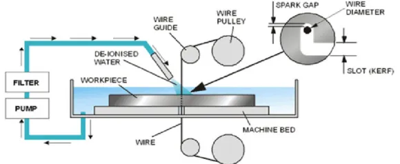
amid EDM. Figure 1 shows the working principle of wire EDM3.
Figure 1: Working principle of wire EDM process
In this work, the following objectives are addressed:
Machining of AISI 4130 steel alloy by using Wire EDM.
To conduct the experiments by varying the control parameters such as Pulse on time, Pulse
off time, Pulse peak current and Water pressure with de – ionized water is utilized as a
dielectric liquid during machining of 10 mm diameter hole on AISI 4130 Steel Alloy.
To optimize process parameters to improve machining features such as Kerf Width and
IJSRR, 8(2) April. – June., 2019 Page 2762
Find out the most influential process parameters of AISI 4130 Steel Alloy using Wire EDM
by ANOVA.
EXPERIMENTAL SETUP
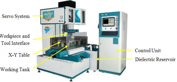
The experimental setup of the wire EDM is shown in Figure 2. Mainly, it consists of six parts
which are explained below4.
Figure 2: Experimental setup of MIG welding
1. Dielectric Reservoir, Pump and Circulation System: For each run of the experiment,
dielectric reservoirs and pumps are used to circulate the EDM oil and the EDM oil filter is
also used.
2. Power Generator and Control Unit: It has a time control function that controls the length
of time during each pulse that the current flows; this is called “on time”. The amount of
current allowed to flow during each pulse is then controlled. These pulses are measured in
microseconds and of very short duration. The control unit controls machining functions such
as Ton, Ip, Duty Cycle, setting values and maintaining the tool gap on the workpiece.
3. Working Tank with Work Holding Device: All the EDM oil in the working tank is utilized
to supply the liquid amid the machining procedure and the work holding gadget is utilized to
hold the workpiece in a fixed position amid the machining procedure..
4. X – Y Table Accommodating the Working Table: It is used to give the workpiece moment
in X and Y directions.
5. Servo System to Feed the Tool: To maintain the predetermined gap, the servo control unit is
provided. It senses the gap voltage and compares it to the current value and then the different
voltage is used to control the servo motor movement to adjust the gap.
IJSRR, 8(2) April. – June., 2019 Page 2763
EXPERIMENTATION
A series of experiments are carried out based on the Taguchi design on AISI 4130 steel alloy
workpiece by using wire EDM with de – ionized water is utilized as a dielectric medium5. The
details of the experiment are as follows:
AISI 4130 steel alloy workpiece is machined using distinctive control factors such as Pulse
on time, Pulse off time, Pulse peak current and Water pressure. The Chemical composition, Physical
properties of AISI 4130 steel alloy and the chosen control parameters & their levels are scheduled in
Table 1, Table 2 and Table 3.
Table 1: Chemical Composition of AISI 4130 Steel Alloy
C Cr Fe Mn Mo P Si S
0.28 – 0.33 0.80 – 1.1 97.03 – 98.22 0.40 – 0.60 0.15 – 0.25 ≤ 0.035 0.15 – 0.30 ≤ 0.040
Table 2: Mechanical properties of AISI 4130 steel alloy Yield Strength (MPa) Tensile Strength (MPa) Modulus of Elasticity (GPa) Poisson’s Ratio Hardness (HB) Bulk Modulus
(GPa) Machinability
435 670 205 0.29 197 140 70%
Table 3: Process parameters and their levels Process Parameter Level 1 Level 2 Level 3
Pulse on time (µsec.) 100 102 104
Pulse off time (µsec.) 50 51 52
Pulse peak current (Amps) 1 2 3
Water pressure (Kg/cm2) 80 85 90
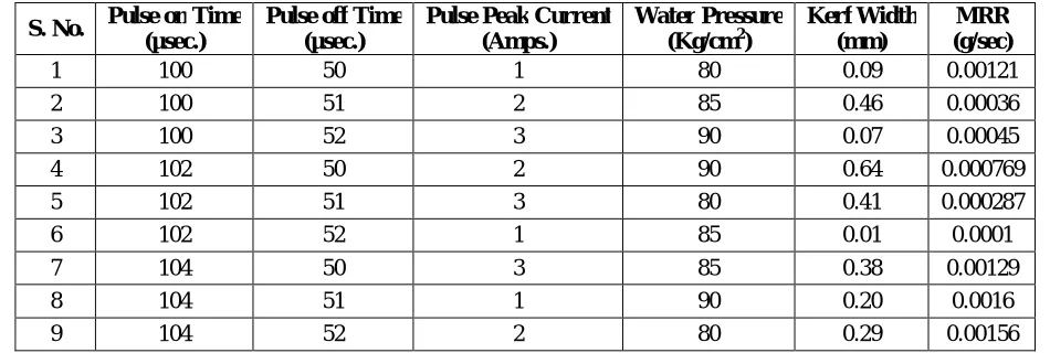
Based on the control parameters and their levels, the experiments are carried out on the basis
of Taguchi experiment design with L9 Orthogonal Array and the responses are shown in Table 4.
Table 4: Experimental results for 4130 steel alloy S. No. Pulse on Time
(µsec.)
Pulse off Time (µsec.)
Pulse Peak Current (Amps.)
Water Pressure (Kg/cm2)
Kerf Width (mm)
MRR (g/sec)
1 100 50 1 80 0.09 0.00121
2 100 51 2 85 0.46 0.00036
3 100 52 3 90 0.07 0.00045
4 102 50 2 90 0.64 0.000769
5 102 51 3 80 0.41 0.000287
6 102 52 1 85 0.01 0.0001
7 104 50 3 85 0.38 0.00129
8 104 51 1 90 0.20 0.0016
9 104 52 2 80 0.29 0.00156
IJSRR, 8(2) April. – June., 2019 Page 2764
Figure 3: Machined workpieces after cutting
RESULTS AND DISCUSSION
Based on the resonances obtained in Table 4, the S/N ratios and ANOVA responses for Kerf
width and Material Removal Rate are calculated using Minitab software6.
Kerf Width Vs Process Parameters
Equation (1) is used to calculate the S / N ratios for kerf width. The Taguchi method is used
to analyze the results of the machining parameter response in categorize to smaller the better criteria.
For smaller the better:
S/N = – 10*log10 (Σ (Yi2/n) --- (1)
Where, Yi = investigational value in the ith, n = number of replications. Where the S/N
proportions are determined from experimental values, yi represents the experimentally observed
value of the ith experiment and n=1 is the repetitive number of each investigation in L9 is conducted.
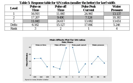
Table 5: Response table for S/N ratios (smaller the better) for kerf width Level Pulse on
Time
Pulse off Time
Pulse Peak Current
Water Pressure
1 16.919 11.065 24.965 13.137
2 17.207 9.490 7.124 18.383
3 11.045 24.617 13.082 13.651
Delta 6.162 15.127 17.840 5.246
Rank 3 2 1 4
Figure 4: Main effects plot for kerf width
1 04 10 2 10 0 2 5
2 0
1 5
1 0
5
52 5 1
50 1 2 3 80 8 5 90
Pulse on time
M
e
a
n
o
f
S
N
r
a
ti
o
s
Pulse off time Pulse peak current Water pressure
Main Effects Plot for SN ratios Data Means
IJSRR, 8(2) April. – June., 2019 Page 2765
Table 6: Analysis of Variance Results for Kerf Width Source DF Seq SS Adj SS Adj MS % Cont.
Pulse on Time 2 72.55 72.554 36.277 7.025
Pulse off Time 2 414.95 414.955 207.477 40.183
Pulse peak current 2 494.97 494.973 247.486 47.932
Water pressure 2 50.17 50.173 25.087 4.841
Total 8 1032.65 100
From Table 5 and Figure 4, the optimum parameters for a smaller Kerf width are observed is
obtained at pulse on time 104 µsec, pulse off time 51 µsec, pulse peak current 2 Amp and water
pressure 80 Kg/cm2 and also from ANOVA Table 6, pulse peak current (47.932%) is the most
influential parameter.
MRR Vs Process Parameters
Based on Equation (2), the S / N ratios for material removal rate are calculated. Taguchi
method is used to analyze the result of the machining parameter response in order to larger the better
criteria7& 8. For larger the better
S/N = – 10*log10 (Σ (1/Yi2)/n) --- (2)
Where, Yi = investigational value in the ith, n = number of replications. Where the S/N
proportions are determined from experimental values, yi represents the experimentally observed
value of the ith experiment and n=1 is the repetitive number of each investigation in L9 is conducted.
Table 7: Response table for S/N ratios (larger the better) for material removal rate Level Pulse on Time Pulse off Time Pulse Peak Current Water Pressure
1 – 64.72 – 59.47 – 64.75 – 61.77
2 – 71.04 – 65.21 – 62.43 – 68.89
3 – 56.61 – 67.69 – 65.19 – 61.71
Delta 14.43 8.22 2.76 7.18
Rank 1 2 4 3
Figure 5: Main effects plot for material removal rate
10 4 10 2 1 00 -55 .0 -57 .5 -60 .0 -62 .5 -65 .0 -67 .5 -70 .0 -72 .5 5 2 51
50 1 2 3 8 0 8 5 90
Pulse on time
M e a n o f S N r a ti o s
Pulse off time Pulse peak current Water pressure
Main Effects Plot for SN ratios
Data Means
IJSRR, 8(2) April. – June., 2019 Page 2766
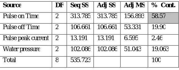
Table 8: Analysis of variance results for material removal rate Source DF Seq SS Adj SS Adj MS % Cont.
Pulse on Time 2 313.785 313.785 156.893 58.57
Pulse off Time 2 106.661 106.661 53.331 19.90
Pulse peak current 2 13.191 13.191 6.595 2.46
Water pressure 2 102.086 102.086 51.043 19.063
Total 8 535.723 100
From Table 7 and Figure 5, the optimum parameters for a larger material removal rate is
observed at pulse on time 104 µsec, pulse off time 50 µsec, pulse peak current 2 Amp and water
pressure 80 Kg/cm2 and also from ANOVA Table 8, pulse on time (58.57%) is the most influential
parameter.
CONCLUSION
The following conclusions are drawn:
Using brass wire of 0.25 mm electrode with de – ionized water as a dielectric medium, 10
mm holes are machined on AISI 4130 steel alloy by varying the control parameters such as
pulse on time, pulse off time, pulse peak current and water pressure.
From the results of S/N ratios:
o It is observed that the optimum parameters are obtained at pulse on time 104 µsec,
pulse off time 51 µsec, pulse peak current 2 Amp and water pressure 80 Kg/cm2
exhibits minimum Kerf width than the other machined holes.
o It is observed that the optimum parameters are obtained at pulse on time 104 µsec,
pulse off time 50 µsec, pulse peak current 2 Amp and water pressure 80 Kg/cm2
exhibits maximum Material Removal Rate than the other machined holes.
From the ANOVA results:
o It is observed that based on % contribution values, pulse peak current has great
influence on kerf width
o It is observed that based on % contribution values, pulse on time has great influence
on material removal rate.
ACKNOWLEDGMENTS
Authors are grateful to Department of Mechanical Engineering, S.V.U. College of Engineering,
S.V. University, Tirupati – 517 502 for providing the necessary equipments, tools and continuous
IJSRR, 8(2) April. – June., 2019 Page 2767
REFERENCES
1. Kuppan P, Rajadurai A, Narayanan S. “Effect of EDM Parameters on Hole Quality
Characteristics in Deep Hole Drilling of Inconel 718 Super alloy”. International Journal of
Manufacturing Research (IJMR)., ISSN: 1750-0591, 2015; 10(1).
2. Kuppan P, Rajadurai A, Narayanan S. “Influence of EDM Process Parameters in Deep Hole
Drilling of INCONEL 718”. International Journal of Advance Manufacturing Technology.,
Springer, 2007
3. Kamaljit Singh, Kalra CS. “An Experimental Investigation: Machining of OHNS Die Steel
by EDM”. Journal of Engineering, Computers and Applied Sciences, 2013; 2(6): 39-42.
4. Kapil Banker, Ujjval Prajapati, Jaimin Prajapati, Paras Modi. “Parameter Optimization of
Electro Discharge Machine of AISI 304 Steel by Using Taguchi Method”. International
Journal of Application or Innovation in Engineering & Management., 2014; 3(8): 20-24.
5. Anand Nikalje N, Umesh Hambire V. “Analysis of the Influence of EDM Parameters on
Surface QUALITY, MRR, EWR and Micro Hardness of AISI O2”. International Journal of
Scientific & Engineering Research, ISSN: 2229-5518, 2014; 5(3).
6. Ghewade DV, Nipanikar SR. “Experimental Study of Electro Discharge Machining for
Inconel Material”. Journal of Engineering Studies and Research, ISSN: 0976-7916, 2011;
2(2): 107-112.
7. Seiji Kumagai, Naoki Sato and Koichi Takeda. “Operation Parameter Optimization for
Fabrication of Narrow, Deep Hole in Metal by Electrical Discharge Machining Using a
Dielectric-Encased Wire-Electrode”. Journal of Material Processing Technology, 2007;
189(1-3): 310-315.
8. Liao YS, Huang JT, Chen YH. “A Study to Achieve a Fine Surface Finish in Wire – EDM”.