Scholarship@Western
Scholarship@Western
Electronic Thesis and Dissertation Repository
8-19-2016 12:00 AM
WebGL-Based Simulation of Bone Removal in Surgical
WebGL-Based Simulation of Bone Removal in Surgical
Orthopeadic Procedures
Orthopeadic Procedures
Arezoo Tony
The University of Western Ontario Supervisor
Dr. Remus Tutunea-Fatan
The University of Western Ontario Joint Supervisor Dr. Roy Eagleson
The University of Western Ontario
Graduate Program in Electrical and Computer Engineering
A thesis submitted in partial fulfillment of the requirements for the degree in Master of Engineering Science
© Arezoo Tony 2016
Follow this and additional works at: https://ir.lib.uwo.ca/etd
Part of the Other Computer Engineering Commons
Recommended Citation Recommended Citation
Tony, Arezoo, "WebGL-Based Simulation of Bone Removal in Surgical Orthopeadic Procedures" (2016). Electronic Thesis and Dissertation Repository. 4043.
https://ir.lib.uwo.ca/etd/4043
This Dissertation/Thesis is brought to you for free and open access by Scholarship@Western. It has been accepted for inclusion in Electronic Thesis and Dissertation Repository by an authorized administrator of
The effective role of virtual reality simulators in surgical operations has been demonstrated during the last decades. The proposed work has been done to give a perspective of the actual orthopeadic surgeries such as a total shoulder arthroplasty with low incidence and visibility of the operation to the surgeon. The research in this thesis is focused on the design and implementation of a web-based graphical feedback for a total shoulder arthroplasty (TSA) surgery. For portability of the simulation and powerful 3D programming features, WebGL is being applied. To simulate the reaming process of the shoulder bone, multiple steps has been passed to be able to remove the volumetric amount of bone which was touched by the reamer tool. A fast and accurate collision detection algorithm utilizing Möller –Trumbore ray-triangle method was implemented to detect the first collision of the bone and tool mesh objects in order to accelerate the computations for the bone removal process. Once the collision detected, a mesh Boolean operation using CSG method is being invoked to calculate the volumetric amount of bone which is intersected with the tool to be removed. This work involves the user interaction to transform the tool in a Three.js scene for the simulated operation.
Keywords
ii
Acknowledgments
iii
Table of Contents
Abstract ... i
Acknowledgments ... ii
Table of Contents ... iii
List of Tables ... viii
List of Figures ... ix
Chapter 1 ... 1
1 Introduction ... 1
1.1 Overview ... 1
1.2 Joints and Implants ... 1
1.3 Shoulder ... 2
1.3.1 Anatomy ... 2
1.4 Total Shoulder Replacement Arthroplasty ... 3
1.4.1 Surgical Techniques ... 4
1.4.2 Glenoid Reaming Procedure ... 4
1.4.3 TSA Challenges ... 5
1.5 Virtual Reality Simulators for Surgical Training ... 6
1.5.1 WebGL: Interactive 3D Computer Graphics API ... 8
1.5.2 Three.js Library ... 9
1.6 Rationale ... 10
1.6.1 Motivation ... 10
1.6.2 Objectives and Hypothesis ... 10
1.6.3 Contribution ... 12
1.7 Structure of the Thesis ... 12
iv
2 Simulator Framework ... 14
2.1 Overview ... 14
2.2 Framework Architecture ... 14
2.2.1 Input device ... 15
2.2.2 Graphical Module ... 16
2.2.3 Computational Module ... 16
2.2.4 Output Device: Display ... 17
2.3 Scenario of the Simulator... 18
2.3.1 Users in the Scenario... 19
2.4 Development Environment ... 19
2.4.1 Modular design ... 19
2.4.2 OpenGL Framework ... 20
2.4.2.1 OpenGL Libraries ... 20
2.4.2.2 OpenGL Versions ... 21
2.4.2.3 OpenGL’s Rendering Pipeline ... 22
2.4.3 WebGL: OpenGL ES 2.0 for the Web ... 27
2.4.3.1 Shaders in WebGL ... 28
2.5 Chapter Summary ... 28
Chapter 3 ... 29
3 Targeting Simulator: Graphical Module ... 29
3.1 Overview ... 29
3.2 Scenario Design ... 29
3.3 Scene and Scene Objects ... 30
3.3.1 Components of the Scene in ThreeJs ... 31
3.3.2 Cameras in ThreeJs ... 31
v
3.3.2.2 Perspective Camera ... 34
3.3.3 Renderers in ThreeJs ... 36
3.3.4 Light Sources in ThreeJs ... 37
3.3.5 Mesh Input ... 41
3.3.5.1 Rendered Objects ... 41
3.3.5.2 OBJ File Format and Loader ... 41
3.4 Simulation Components ... 44
3.4.1 Time Keeper Component ... 44
3.4.2 Parameter Tracking Component ... 45
3.4.3 Logging Component ... 45
3.5 User Interaction ... 45
3.5.1 Matrix Transformation ... 48
3.5.1.1 Orientation and Translation ... 48
3.5.2 Mouse and Keyboard ... 51
3.5.3 Leap Motion ... 51
3.5.4 Haptic Device ... 52
3.6 Import and Export Objects ... 53
3.7 Chapter Summary ... 53
Chapter 4 ... 54
4 Targeting Simulator: Computational Module ... 54
4.1 Overview ... 54
4.2 Divide and Conquer Algorithm ... 54
4.3 Parallelism in JavaScript ... 56
4.4 Computational Framework ... 57
4.5 Collision Detection ... 60
vi
4.5.2 Separating Axis Theorem ... 62
4.5.3 Circle Collision ... 62
4.6 Collision Performance ... 63
4.6.1 Broad Phase ... 63
4.6.2 Narrow Phase ... 63
4.6.3 Möller -Trumbore Algorithm ... 64
4.6.3.1 Algorithm ... 64
4.6.3.2 Implementation of the MTalgorithm ... 69
4.7 Mesh Boolean Operation ... 74
4.7.1 CSG Method: Constructive Solid Geometry ... 76
4.7.1.1 Create BSP- Tree ... 78
4.7.1.2 Merge Two Trees ... 80
4.7.1.3 Optimization in CSG Method ... 83
4.8 Chapter Summary ... 85
Chapter 5 ... 86
5 Performance Evaluation ... 86
5.1 Overview ... 86
5.2 Objectives ... 86
5.3 Collision Detection ... 86
5.4 Mesh Boolean Operation ... 89
5.5 Evolution of Bone Geometry during Reaming Procedure ... 93
5.6 Dependence of Hardware/Software Platform ... 94
5.7 Chapter Summary ... 97
Chapter 6 ... 98
6 Closing Remarks ... 98
vii
6.2 Implementation Challenges and Lessons Learned... 99
6.3 Future Direction ... 100
Bibliography ... 101
viii
List of Tables
Table 1-1 Incidence rate of most common joint surgeries ... 7
Table 3-1 TrackBall controls and actions in Three.js ... 46
Table 3-2 Orbit controls in Three.js ... 47
Table 5-1 Comparison of the bone vertices and faces in 4 experiments ... 94
Table 5-2 Tests on different browsers and different computers ... 95
ix
List of Figures
Figure 1-1 Implant fixation in Total Shoulder Arthroplasty ... 2
Figure 1-2: The anatomy of the shoulder ... 3
Figure 1-3 Glenoid reaming process ... 5
Figure 1-4: Glenoid resurfacing using reamer Adapted from [http://shoulderarthritis.blogspot.ca/2011_05_01_archive.html] ... 6
Figure 2-1 The Framework Architecture Diagram ... 15
Figure 2-2 Different input devices ... 16
Figure 2-3 Output devices in surgical simulators ... 18
Figure 2-4 OpenGL Rendering Pipeline ... 26
Figure 3-1 Scenario design use case diagram ... 30
Figure 3-2 Orthographic Camera Properties ... 33
Figure 3-3 Three.js Orthographic Camera ... 33
Figure 3-4 Perspective Camera Properties ... 35
Figure 3-5 Three.js Perspective Camera ... 35
Figure 3-6 Rendering the scapula using ambient light ... 38
Figure 3-7 Rendering the scapula using point light ... 38
Figure 3-8 Rendering the scapula using directional light ... 39
x
Figure 3-11 Scapula bone and virtual reamer ... 44
Figure 4-1 Computational module framework diagram ... 58
Figure 4-2 Wireframe mesh representation of the bone and reamer ... 59
Figure 4-3 Bounding Box representation of the bone and reamer ... 61
Figure 4-4 Intersection point inside a triangle in barycentric coordinates ... 65
Figure 4-5 Cartesian to barycentric coordinate system conversion ... 67
Figure 4-6 Boolean Operations ... 76
Figure 4-7 Example of a CSG tree adopted from https://en.wikipedia.org/wiki/Constructive_solid_geometry ... 77
Figure 4-8 BSP-Tree Creation ... 79
Figure 4-9 Split a Triangle in BSP-Tree ... 80
Figure 4-10 Merge the two BSP-Trees ... 81
Figure 4-11 Reamer and Scapula Computational Volume ... 84
Figure 5-1 Bounding Box Collision Alert ... 87
Figure 5-2 Collision detection Alert ... 88
Figure 5-3 Mesh Boolean Subtraction of the Reamer on the Bone ... 89
Figure 5-4 Subtraction on the Scapula Bone ... 90
Figure 5-5 Scapula Bone Before and After Subtraction ... 91
Figure 5-6 Original Bone Wireframe Representation ... 91
Figure 5-7 Subtracted Bone Wireframe Representation ... 92
Chapter 1
1
Introduction
1.1
Overview
This introductory chapter reviews shoulder anatomy and the Total Shoulder Arthroplasty procedure. This chapter also contains the challenges of the Total Shoulder Arthroplasty and the reason a virtual reality simulator is being developed using WebGL which could be a solution to all types of all bone removal procedures.
1.2
Joints and Implants
Joints are the area of the body at which the bones are attached in purpose of body movements. A joint is usually formed by connective tissues and cartilage. Joints are mainly classified structurally which determines how the bones connect to each other and functionally in which the degree of the movement between the bones is being focused. Functionally, joints can be classified into three categories; 1) synarthrosis joints with limited or no mobility, 2) amphiarthrosis joints with slight mobility and 3) diarthrosis joints with freely movements such as shoulder, elbow, hip and knee which are more likely to be injured (Whiting and Rugg 2006).
fixation of the implant (Figure 1-1) into the cavity of the bone is all-important to bring back the functional joint (Nuss and von Rechenberg 2008).
Figure 1-1 Implant fixation in Total Shoulder Arthroplasty
Adapted from [http://www.mayoclinic.org]
1.3
Shoulder
1.3.1
Anatomy
1-2). The shoulder is a ball and socket joint in which the ball is the humeral head and the socket is called glenoid (Karelse et al. 2014) where the head of the upper arm bone fits into it. The smooth cartilage surface of the shoulder allows the ball and the socket, one to move smoothly along the other and helps to maintain the stability of the shoulder.
Figure 1-2: The anatomy of the shoulder
1.4
Total Shoulder Replacement Arthroplasty
Shoulder arthritis occurs when the smooth cartilage surface of the shoulder disappears which results in a “bone on bone” joint which is painful. Thus new surfaces can be a robust and reliable solution to restore comfort.
1.4.1
Surgical Techniques
Compared to the previous similar procedure (drilling), reaming has great advantages. Drilling is a procedure in which a hole is being made out of the bone removal using the drill tool in the scapula for the fixation of the implant, while reaming resurfaces the bone. The volumetric amount of the bone removal is not comparable to the reaming procedure which removes the maximum volume of 2mm of surface of the bone to make the smooth congruent surface.
1.4.2
Glenoid Reaming Procedure
Glenoid reaming is a task in Total Shoulder Arthroplasty in which the glenoid cavity is resurfaced in order to provide a congruent, smooth surface for fixation of implant (Saltzman et al. 2011).
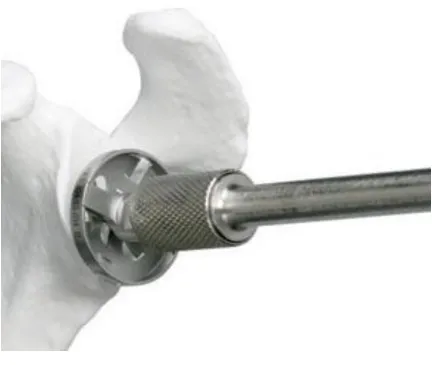
Figure 1-3 Glenoid reaming process
Adapted from [http://faculty.washington.edu]
1.4.3
TSA Challenges
1.5
Virtual Reality Simulators for Surgical Training
The effectiveness of virtual reality based training simulators for orthopaedic surgery has been extensively investigated and demonstrated over the last two decades(Vaughan et al. 2016). However, there are always more complications and less control precision in surgical procedures for novice trainees. Additionally, the majority of simulators tend to be focused on lower limb, whereas upper limb procedures are equally or could be regarded as even more challenging due to their lower incidence (Sperling, Cofield, and Rowland 2004; Vaughan et al. 2016) in the population that in turn translates into limited training and practice opportunities. Among upper limb procedures, total shoulder replacement involving glenoid resurfacing (Figure 1-4) pose significant challenges, particularly since cutting tool/bone interface cannot be directly visualized in real-time during the glenoid reaming operation.
As can be seen in Table 1-1, the shoulder surgeries happens around 53,000 per year in US which is comparing to the number of more than 90,000 for hip and knee replacement surgeries(“Shoulder Joint Replacement-OrthoInfo - AAOS” 2016). While the scope of a virtual orthopaedic simulator is broad and it includes several modules addressing different types of augmented feedback to guide the actions of the surgical trainee(Figure 1-5), the present study was solely focused on the development of the graphical rendering module. The core of this graphics module – aiming to deliver explicit visual feedback on the location of the bone removed as a function of the reamer posture (i.e., position and
orientation) – can be reduced to a conventional Boolean operation between two objects.
Table 1-1 Incidence rate of most common joint surgeries
Figure 1-5 Orthopedic haptic drilling simulator by Vankipuram et al
1.5.1
WebGL: Interactive 3D Computer Graphics API
Processor Unit (GPU). Besides, previous surveys in Medical Image rendering show the robustness of WebGL in handling large geometries(Cantor-Rivera, Bartha, and Peters 2011).
WebGL provides a real-time interactive 3D web based environment which allows the trainees and surgeons to overcome the classic desktop software tools and access the applications through a desired web browser exclusive of a specific operating system, without extra plug-ins or particular third party components (Chen and Xu 2011).
In this work, a real-time simulator of a tool-bone interaction during glenoid reaming is proposed to demonstrate the use of collision between the two main objects (bone and reamer) as well as the total shoulder resurfacing procedure while the process of reaming in case of more complex geometries to determine the amount of volumetric interference between the two penetrating objects. The simulator is also constituted by a navigation tool for the user interaction to have the better and more precise training performance.
1.5.2
Three.js Library
files. Having loaders and exporters in the directory of Three.js allows to respectively import and export types of files containing JSON, OBJ, STL and MTL.
1.6
Rationale
1.6.1
Motivation
The growing evolution of surgical simulator industry has provided a drastic development of even more powerful virtual reality simulators that are capable of real-time interactive environment between the trainees and the various feedbacks more specifically graphical module.
The motivation of this design is to ease the preoperative task required while replacing the shoulder joint with the prosthesis. The virtual reality simulator for the Total Shoulder Arthroplasty (TSA) would help the trainees and the surgeons to have a better tangible perspective of the real surgery. While it is true that there is a growing body of research on the orthopeadic simulators, existing solutions are typically expensive and slow, considering that the simulator is the type of surgical and should be real-time and interactive to achieve the best results out of the training.
Existing research on the virtual reality simulator of the TSA focusing on bone removal is the first time being explored during reaming procedure for training and education purposes.
1.6.2
Objectives and Hypothesis
the residents and surgeons before the real surgery. To accomplish this task, a Web-based graphical interface has been developed of a tool-bone interaction during glenoid reaming process to demonstrate the use of collision detection between the two objects as well as the bone resurfacing in case of more complex geometries to determine the amount of volumetric interface intersected in the bone out and from the reamer tool.
A fundamental purpose of the proposed research is to provide the trainees and surgeons with a realistic, three-dimensional representation of each step of the given procedure. The developed method will permit a precise bone removal procedure with less amount of damage to the glenoid and more accurate replacement of the implant into the bone.
To address this purpose and goal, the objectives of this work are:
1) To develop a web-based graphical interface of the surgery to enable user interaction of the tool while bone removal procedure.
2) To develop a fast algorithm in purpose of finding the first collision between the two intersecting objects.
1.6.3
Contribution
The major contribution of the proposed research is the development of a virtual reality simulator of a TSA. To accomplish this, several algorithms and methods within the scope of this study aimed to represent the information of the tool-bone intersection including the minimum distance, the first intersected points of the collision, the intersection part -the amount of penetration between two objects- and reconstruct -the bone once -the two objects collide.
This work is the first attempt of WebGL development in the context of simulating the real-time bone removal while reaming procedure in orthopeadic surgeries. By utilizing the developed techniques, surgeons can assess the volumetric amount of bone removed in the graphical module while using the haptic device, vibration and sound feedback. Utilizing WebGL, surgeons are able to run the simulation on portable platform and on a desired web browser either on a computer or a mobile platform exclusive of the hardware and software.
1.7
Structure of the Thesis
This document will discuss about a web-based surgical simulator using WebGL which contains the graphics and the computations in the following chapters.
Chapter 2 outlines the main scenario of the framework including the elements. This chapter also contains the architecture of the framework and complications of the simulator implementation.
libraries, the graphic features such as GUI and utilized to implement a powerful graphics and visual experience of the real procedure in the surgery.
Chapter 4 outlines the main numerical algorithms of the proposed research including all the developed functions and libraries as well as the main procedure of the simulator to resurface the bone and regenerate the mesh object using Möller -Trumbore method to implement the collision detection algorithm in order to find the minimum distance between the two objects and the vertex candidates for the first collision and also the CSG method to implement the mesh Boolean operation between the bone and the surgical tool.
Chapter 5 describes the performance evaluation of the developed surgical simulator and algorithms. It contains the main results of the proposed research using the new techniques and algorithms.
Chapter 2
2
Simulator Framework
2.1
Overview
This chapter contains the main scenario of the framework including the elements; trainee who will perform the tasks and respond to the events in the scenario of the implemented simulator and events or actions which the trainee try to perform. This chapter also contains the architecture of the framework and complications of the simulator implementation.
2.2
Framework Architecture
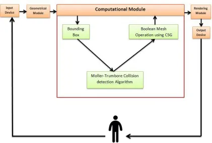
Figure 2-1 illustrates the main diagram of the architecture of the framework related to the proposed work.
Figure 2-1 The Framework Architecture Diagram
2.2.1
Input device
Input device is a piece of computer hardware that allows the user to interact with the graphics. Input devices can be varied based on the purpose of the software applications including keyboard and mouse for most of the applications and computer games as the basic input devices, Leap Motion sensor device for virtual reality simulators and haptic devices for surgical simulators consisting force computations. Input devices can be also classified based on modality or the number of degree of freedom.
Figure 2-2 Different input devices
2.2.2
Graphical Module
The main module of the proposed work is the graphics which includes the main WebGL code containing 3D programming using Three.js. This module provides the classes consisting of user interface menu, imported objects, classes containing the main information of the computational function results, windows settings and more classes which will be explained in both graphical and computational module sections.
The graphical module will be discussed in the next chapter.
2.2.3
Computational Module
The graphics is the interface between the user input and the computational module which contains all the functions and the algorithms implemented in the proposed project.
The computational module also provides an algorithm and a library in JavaScript which computes the volume of the intersected bone in each step of collision and removes the intersection volume from the geometry. It utilizes the Constructive Solid Geometry method for the use of Boolean operations on the mesh objects. The method, calculations and the library will be discussed in chapter 4.
2.2.4
Output Device: Display
Once the flow passes the computational modules and run the functions and algorithms by the user request received from the input device through the graphical module, it reaches the output device to display the results on the screen. The user then can view the results of own interaction to get a perspective of what is being executed during the reaming process.
The proposed project only contains the graphical module with the related computations while the main project and the final simulator also contains the Audio module, Vibration module and Haptic module which help the surgeon more about the reaming process.
Figure 2-3 Output devices in surgical simulators
2.3
Scenario of the Simulator
One of the main goals of the framework is to allow any type of scenario to be executed, for instance any type of implant replacement surgical procedure scenarios including total shoulder/hip/knee arthroplasty or even non-surgical related scenarios such as entering data into a web-based game application.
A scenario in the context of the hierarchical-based framework contains various elements: a user, a sequence of events and a context. The user has the role to respond to the events in the scenario. The events contain all the actions performed by the user (surgeon). And the context explains the environment in which the scenario is being taken.
2.3.1
Users in the Scenario
In the described scenario, user is the trainee or the surgeon who will do the experiment to evaluate the performance of the surgery. A user participates in the flow of the events to interact with the graphical module in 3-dimensional environment.
2.4
Development Environment
The implemented web application is for use on any web browsers and operating systems. The programming language used for this application is JavaScript; a high-level, dynamic script language. Alongside HTML and CSS, JavaScript is one of the three core
technologies of World Wide Web (www) supported by all modern browsers without the use of any plug-ins. JavaScript also supports the object-oriented concepts and functional programming style which is critical for the good design of large software projects as well as containing various libraries, platforms and technologies that allows the program using the specific powerful features of it. JavaScript also allows creating a professional design of Graphical User Interface for the Virtual Reality based simulators.
2.4.1
Modular design
The structure of the proposed system is designed modular which is subdivided into smaller reusable modules and functions to reduce the cost as well as increasing the flexibility of the system. Similar functions are grouped in one unit of programming section and separate functions are developed in separate sections so that the code can be reused multiple times and by other applications.
enables multiple programmers to divide the whole project into smaller sections and be able to program and debug pieces of the code independently and shortly and the scope of variables can be easily controlled.
In the proposed project, modular programming in JavaScript allows the main project to be implemented into different modules and classes to reuse the same functionality in different part of the program. For instance, collision detection algorithm should be checked every time the user moves the reamer object along to the bone object to detect the first collision. Furthermore, once the collision happens, the Boolean mesh operation get involved. This class is one of the usable modules which will be invoked as many times as the user continue the process of the bone removal to get the desired, smooth surface of the scapula.
2.4.2
OpenGL Framework
As named by Khoronos, OpenGL (Open Graphics Library) is the most widely adopted 2D and 3D graphics API in industry. OpenGL has the latest and newest graphic hardware features so developers could enable high performance of graphics on the application markets such as gaming, entertainment and virtual reality to achieve hardware accelerated rendering. It has the direct access to the graphical processor unit as well as providing a robust platform such as WebGL.
2.4.2.1
OpenGL Libraries
There is an OpenGL utility toolkit called GLUT which allows the OpenGL program for opening a window or managing inputs. GLUT has two versions: first is the free version which is called Freeglut and second is the original version of the GLUT which is not an updated version.
Another useful library is Glew that helps for loading and querying the OpenGL Extensions. Glew is responsible to check the OpenGL Extensions based on the specific platform.
There are a variety of OpenGL libraries regarding the purpose of the program. But the mentioned above libraries are among the most useful ones which are included in almost all the programs exclusive of the purpose.
2.4.2.2
OpenGL Versions
OpenGL is and evolving API with new versions and features released by Khronos Group. The first version, OpenGL 1.0 , was released in 1992(Shreiner et al. 2013). Since then, there are both many versions and libraries of OpenGL for simplifying the development of more complicated video games or medical software tools.
Several versions of the OpenGL ES have been released. The first, OpenGL ES 1.0 was released in 2003 with some differences compared to the OpenGL. Removing the brackets of OpenGL library calls for begin and end, adding fixed point data type for vertex coordinates, removing several technical drawing modes, eliminating display lists and feedbacks and many other extra features to make it a more lightweight API.
OpenGL ES 1.1 had quite the same features as the previous version except some small changes such as vertex buffer object and multi-texture support.
OpenGL ES 2.0 was released in 2008 which is based on OpenGL 2.0 with some modifications in the rendering pipeline. Rendering features of lighting and transformation are replaced by Shaders in GLSL so it became a shader-based rendering pipeline using vertex and fragment shaders. It can be supported by Android and IOS platforms and various other platforms. Most of all, it can be supported by web browsers using WebGL.
2.4.2.3
OpenGL’s Rendering Pipeline
OpenGL rendering pipeline is the sequence of steps for converting the data into the final OpenGL rendered image.
Vertex Specification:
For the very first stage, OpenGL needs all data to be stored in the buffer mostly with the glBufferData () command.
Next stage is vertex processing which contains three levels: 1) Vertex shader, 2) Tesselation, 3) Geometry shading.
Vertex Shading:
Vertex shader is a piece of program which receives each vertex as an input containing all its attributes, processes the vertex and produces an output vertex.
After buffer initialization, geometric primitives should be rendered with glDrawArrays () command. By drawing, OpenGL transfers data to the server. Vertex is a bundle of data which includes the position information.
This is a 1:1 input to output mapping stage.
Tessellation:
Geometry Shading:
A geometry shader is a piece of program which is also optional that governs the processing of primitives. This stage is not a 1:1 input to output stage so it receives a single primitive as an input and may have zero or more outputs.
Vertex Post-Processing:
The last stage output comes as an input for psot-processing stage mostly for Primitive Assembly and Rasterization stages. It contains two steps: 1) Transform Feedback which is for recording data from previous stage into buffer object to keep the post-transform rendering state and resubmit it multiple times. 2) Clipping which is primitive clipping of each vertex to the viewport- the permitted region of window to draw- by its clip space position. Different type of primitives can be clipped differently. For instance, points cannot be clipped. If points are outside the clipping view, they will be discarded. But if they are inside, they will be considered. For the lines, if they are partially outside of the volume, they will be clipped and new vertices will be generated. And for triangles, if they are partially inside the clipping view, new triangles will be generated with vertices on the boundary of the volume.
Primitive Assembly:
Rasterization:
The updated primitives are sent to the rasterizer to generate fragments. A fragment can be in the buffer to store the position, while another can be rejected and never update its pixel location. The main processing of the fragments happens in the next two stages.
Fragment Shader:
This is the final stage to determine the color and depth value of a fragment although it can be still modified in the per-sample operation if needed.
The main difference between a vertex and a fragment shader is that a the location of a primitive is determined by the vertex shader while the fragment shader will have the information of the color of that fragment on the screen.
Per-Sample Operation:
Per-fragment operation or per-sample operation is the final stage where some modifications outside the fragment shader can be done. There are some tests in this stage such as Z-buffer or depth testing for the visibility of the fragment. There are also more tests including scissor test, stencil test, blending or logical operations.
If a fragment goes through all the tests successfully, it can be written in the frame buffer and update the color of the pixel.
2.4.3
WebGL: OpenGL ES 2.0 for the Web
Rendering the simulator view of this work is done using WebGL, a cross-platform, DOM API to create 3D graphics in Web Applications (https://www.khronos.org/webgl) for efficient rendering of 3D medical modeling (Cantor-Rivera, Bartha, and Peters 2011). WebGL is the JavaScript implementation of OpenGL ES 2.0 which is a low level API between software and hardware or software applications though HTML5 canvas element which needs a proficient knowledge of 3D programming and math. WebGL could bring the power of low-level programming of OpenGL to the web for the JavaScript developers (Leung and Salga 2010). What makes WebGL unique is that it allows the web browser to directly access the Graphical Processor Unit (GPU). Thus, surgical virtual reality simulators could make use of 3D web visualization in real-time.
WebGL has characteristics including integration to the Document Object Model through HTML canvas element.
Also, WebGL does not need to communicate with the server once the data and the algorithm reach GPU so it can go offline till the scene needs update.
Plus, WebGL has shown the robustness of handling large geometries in various projects such as the tests done by Cantor-Rivera(Cantor-Rivera, Bartha, and Peters 2011).
High-level JavaScript libraries such as Three.js would make it easier and more accessible for the web developers to deal with the 3D math less than the use of pure low-level languages such as GLSL or WebGL.
2.4.3.1
Shaders in WebGL
Shaders get the data and turn it into pixels on the screen. WebGL and OpenGL ES 2.0 are based on shader rendering requiring vertex and fragment shaders. Vertex shader is being processed on each corner of a triangle to transform the points, texture coordinates, get the normal of each triangle to compute the lightings and then pass the output to the fragment shader. Fragment shader runs on each pixel of the transformed triangle passed from vertex shader to receive the color, lighting and texture and output the pixel on the screen. Shaders will be defined in the scripts on top of the program in the HTML Code before the WebGL section.
2.5
Chapter Summary
This chapter included the framework architecture of the proposed work containing all the main elements as well as the OpenGL pipeline. We also included how WebGL works based on OpenGL and the shader programming language to access the GPU.
Chapter 3
3
Targeting Simulator: Graphical Module
3.1
Overview
The main goal of developing a targeting simulator was to design an environment that allows for simulation of a surgical operation and evaluation of the user performance in interaction with the surgical tools in complex procedures with low incidence and visualization. While such a program could be applied using existing software tools such as SolidWorks or Rhinoceros with predefined features of most of the graphics and computations, implementing a virtual reality simulator are aimed to help for the poor visualization of complicated surgeries such as Total Shoulder Arthroplasty utilizing a powerful graphics and visual experience of the real procedure. Web-based simulation using WebGL technology provides an environment exclusive of specific platform and extra plug-ins.
3.2
Scenario Design
diagram of the proposed work. It contains the main elements of the design including their features and configuration attributes such as color, material and position.
Figure 3-1 Scenario design use case diagram
3.3
Scene and Scene Objects
Firstly, a scene should be created to display the objects and user interface menu. The very first step to use Three.js is to include the Three.js library to the code and enable the Three.js syntax.
simulator. Lights, camera, objects and renderer will be discussed in more details in the following sections.
It is easy to set up a new scene, camera and renderer with the following piece of code using Three.js library:
var scene = new THREE.Scene();
var camera = new THREE.PerspectiveCamera( 75, window.innerWidth / window.innerHeight, 0.1, 1000 );
var renderer = new THREE.WebGLRenderer();
renderer.setSize( window.innerWidth, window.innerHeight );
document.body.appendChild( renderer.domElement );
3.3.1
Components of the Scene in ThreeJs
3.3.2
Cameras in ThreeJs
There are two main types of cameras in Three.js: 1) camera with the perspective projection and 2) camera with the orthographic projection.
We also have more types of camera including the combined camera of perspective and orthographic or the CubeCamera () which creates 6 different cameras.
3.3.2.1
Orthographic Camera
For the Orthographic Camera, we need to define a volume in space and make it move and orient around the scene arbitrarily. The following piece of code will create the rectangular box of that volume.
viewSize = 900;
aspectRatio = window.innerWidth / window.innerHeight;
// orthographicCamera (left, right, top, bottom, near, far);
var camera = new THREE.OrthographicCamera( aspectRatio * viewSize / - 2, aspectRatio * viewSize / 2, aspectRatio * viewSize / 2, aspectRatio * viewSize / - 2, -1000, 1000 );
scene.add( camera );
The mentioned above code and the Figure 3-2 and Figure 3-3 shows how the Orthographic Camera works.
Figure 3-2 Orthographic Camera Properties
The following figure shows the properties of the Orthographic camera and how they can affect the view of the scene. As can be seen, all the properties have the same size
regardless of the distance and perspective of the view.
3.3.2.2
Perspective Camera
Perspective camera is like a real world with objects in the distance becoming smaller. Perspective camera works same as the human eye. When the human eye views an object, objects in the distance are smaller which is called perspective. On the other hand, orthographic camera ignores this distance to get the accurate and exact measurement of the objects regardless of the distance.
The following code and Figure 3-4 and Figure 3-5 shows how the perspective camera works. Perspective camera takes fewer arguments than orthographic camera. Fov stands for Field Of View which can be seen from the perspective of the camera. Human’s eye has 180 degree fov. For computer games and applications it is mostly between 60 and 90 degree.
Aspect has the same definition as in the Orthographic camera. This is the aspect Ratio between the horizontal and vertical size of the rendered view. Near and far properties also show the rendering distance from the camera.
// perspectiveCamera (fov, aspect, near, far);
var camera = new THREE.PerspectiveCamera( 45, width / height, 1, 1000 );
scene.add( camera );
Figure 3-4 Perspective Camera Properties
Figure 3-5 shows the difference of the size of the object in terms of distance to the camera.
In the proposed work, an orthographic projection and camera is being used for more accurate results and view of the objects as well as having the real size of the objects while removing the bone surface in the reaming process. Using perspective camera can increase the level of mistakes and extra bone removal.
3.3.3
Renderers in ThreeJs
Three.js has several renderer classes to render with different targets. It includes a WebGL renderer and a canvas renderer. The canvas renderer translates 3D graphics into the 2D canvas API when WebGL is not available, but it doesn't implement many of the more interesting 3D features, and it is generally much slower than the WebGL renderer. In this module, a WebGLRenderer is being defined using the following piece of code:
THREE.WebGLRenderer is a renderer that renders using WebGL:
renderer = new THREE.WebGLRenderer ();
renderer.setClearColor (0xC9CFD1);
renderer.setPixelRatio (window.devicePixelRatio);
renderer.setSize (window.innerWidth, window.innerHeight);
3.3.4
Light Sources in ThreeJs
All the objects in the scene have a material which can be presented with a specific type of light source. Light is an abstract class of Three.js which has two properties to identify the color and intensity of the light. It can be easily created in Three.js with the following piece of code:
var light = new THREE.AmbientLight( 0x404040 );
scene.add( light );
Different types of light sources in Three.js exist in terms of usage and behavior. Furthermore, a combination of different type of light sources can be applied. A brief description of each type will be given to demonstrate the utilized types in the proposed work.
Figure 3-6 Rendering the scapula using ambient light
PointLight: This type of light source is a single point in space which affects objects with lambert and phong material. Figure 3-7 shows the scapula rendering using point light.
SpotLight: This is a point light which could cast a shadow in one direction on the objects with lambert and phong material.
DirectionalLight: This type creates a light from a specific direction and not a position. It behaves as it is infinitely far away from the object like the sun so the ray produced by this would be parallel with the same angle to all the objects. This is the most natural light which can be used for such surgical simulators. Figure 3-8 shows the scapula rendering using directional light.
For the proposed research, a combination of directional, ambient and point lights are applied to get a realistic object rendering in the Three.js scene (Figure 3-9).
Figure 3-9 A combination of directional, ambient and point light for the scapula rendering
//lights
var AmbientLight = new THREE.AmbientLight (0xAB9E91);
AmbientLight.position.set (100,100,400).normalize();
scene.add(AmbientLight);
var Pointlight = new THREE.PointLight(0xAB9E91);
Pointlight.position.set(100,100,400);
scene.add(Pointlight);
directionalLight.position.set(100,100,500).normalize();
camera.add(directionalLight);
3.3.5
Mesh Input
3.3.5.1
Rendered Objects
The role of the scene in Three.js is to render the objects (bone and the reamer) containing all the information which is needed to simulate a virtual reality environment for the surgery.
There are two main objects in the proposed Three.js scene: the bone and the reamer. Both objects are the type of polygon mesh (or triangular surface mesh) objects which contain the information of the triangles which make the surface of the object. The main attributes of the mesh files are the triangles (faces), vertices coordinates which make the triangles, the material as well as the rotation, position and scale information of each.
Three.js has its predefined objects and geometries such as a cube or a sphere that can be rendered easily with Three.js syntax.
In the proposed research, the triangular mesh representation of the virtual reamer obtained from the reverse engineering methods and the virtual glenoid bone obtained from the CT data thus the bone and the reamer would be rendered in the scene through a type of loader based on type of the object.
3.3.5.2
OBJ File Format and Loader
was chosen for the easy access to the geometry information (Dirksen 2014) which is a need for all the calculations and algorithms discussing in the next chapter.
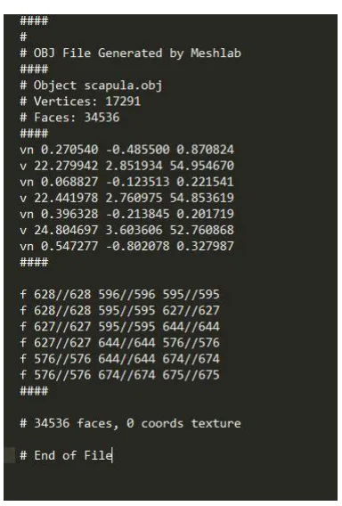
OBJ is a file format developed by Wavefront Technologies. OBJ format is a simple type which contains almost all the required information such as position of the vertices, UV positions of the textures, faces and vertex normal that is typically modeled using programs such as Blender or Maya or Meshlab.
As can be seen from figure 3-10 every OBJ file contains the main information of the vertex position, vertex normal and at the very bottom of the file the faces which contain the vertex indices of the each face (triangle). Also this figure illustrates that the file was generated through meshlab program.
Vertex positions are defined with the prefix v with three components of x, y, z in Cartesian coordinate system.
Vertex Normals represent the normal vector at each vertex with the prefix vn with the same x, y, z components which may be or may not be normalized that should be considered for the rendering and calculations.
Lastly, faces with the prefix f, represent the triangles of the mesh. Each face is comprised of three vertices and each one in the obj file contains three vertex indices which made each triangle usually with counter clock wise order. The order of the vertices in each face is important to distinguish the back of the triangle from the front. It will be discussed more in the collision detection algorithm using Möller -Trumber method in chapter 4.
Three.js has OBJLoader to load the .obj file format. The recent versions of OBJLoaders in Three.js load the buffer geometry which contains the general information of the object to increase the memory usage and decrease the cost of passing all the parameters to the GPU but it does not contain the required information for the calculation of the bone removal algorithm. So, in this work, an older version of OBJLoader (version 68) is being utilized for the purpose of loading the geometry directly and to avoid the conversion of buffer geometry to geometry to update the object matrix after each rotation, translation.
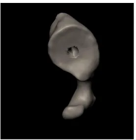
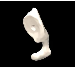
Figure 3-11 Scapula bone and virtual reamer
3.4
Simulation Components
This simulation has a couple of components in order to keep track of the objects and their attributes such as position.
3.4.1
Time Keeper Component
3.4.2
Parameter Tracking Component
This component is to keep track of the objects and their attributes including the position of the object and each vertex, the orientation of the reamer and other important elements which needs to be computed in the collision detection and Boolean operation algorithms.
3.4.3
Logging Component
Logging component contains the most useful information of the calculations such as the minimum distance between the two objects before the collision occurs, or the rotation axis and angle of the reamer after each user interaction to demonstrate the reamer condition towards the scapula bone.
3.5
User Interaction
In information technology, user interface (UI) is designed to allow the user interact with the system through any device such as a display screen, mouse, keyboard, leap motion in games, haptic device in surgical operations and such devices from the human end.
Control over the camera in Three.js could be accomplished using built-in camera controls. The most popular controls are TrackBallControls and OrbitControls.
TrackBallControls is the most used control to utilize the mouse or the trackball in order to easily allow the user to pan, zoom and rotate the camera around the scene. Table 3-1 shows how the TrackBall controls work using mouse.
Table 3-1 TrackBall controls and actions in Three.js
Control Action
Left mouse button and move Rotate the camera around the scene
Scroll wheel Zoom in and zoom out
Middle mouse button and move Zoom in and zoom out
Right mouse button and move Pan around the scene
The first step is to define the control after the camera definition and update the controls in the render function loop. This type of control works really well with perspective camera.
//Trackball controls
trackballControls = new THREE.TrackballControls (camera,renderer.domElement);
controls.rotateSpeed = 0.3;
controls.zoomSpeed = 0.5;
controls.panSpeed = 0.8;
controls.enableZoom = true;
controls.enablePan = true;
controls.enableDamping = true;
controls.dampingFactor = 0.3;
controls.addEventListener('change', render );
OrbitControls is another popular type of control which simulates a satellite in orbit around the Three.js scene to pan and rotate around an object in the scene. Table 3-2 illustrates how the orbit control works.
Table 3-2 Orbit controls in Three.js
Control Action
Left mouse click + move Rotate the camera around the center of the scene
Scroll wheel or Middle mouse click + move Zoom in and zoom out
Right mouse click + move Pan around the scene
Same as the TrackBall control, camera should be defined first and then the Orbit control should be declared. Also, we need to update the controls in the render function loop.
orbitControls = new THREE.OrbitControls(camera);
//Render function
function render () {
requestAnimationFrame(animate);
orbitControls.update(camera);
renderer.render (scene, camera); }
3.5.1
Matrix Transformation
Three.js has its built-in rotation and translation properties which can be used easily to move and rotate the object around the scene. Meanwhile, Three.js is using the matrix transformation behind the scenes for each modification of the object in terms of position and rotation. It is also possible to modify the matrix transformation directly to the geometry or the mesh object.
3.5.1.1
Orientation and Translation
This is how it works using the built-in transformation matrix in Three.js which moves the object 2 steps in the +X, +Y, +Z.
THREE.Matrix4().makeTranslation(2,2,2);
And this is how to make own transformation matrix in Three.js by instantiating the matrix and then apply it on the object:
var translationMatrix = new THREE.Matrix4 (
1, 0, 0, controls.x
0, 1, 0, controls.y
0, 0, 1, controls.z
0, 0, 0, 1 );
After instantiating the transformation matrix, it could be applied on the mesh:
cube.applyMatrix( translationMatrix);
Or it could be applied on the geometry. But it needs to update the vertices positions of the geometry manually as it is not updated automatically.
cube.geometry.applyMatrix(translatoinMatrix);
cube.geometry.verticesNeedUpdate = true;
which is responsible to compute the rotation matrix and apply the translation matrix once the user press the related keys on the keyboard.
//example of a rotation around X axis with Theta degree
case 65: // key a to rotate around X by rotationAngle amount
of radian
ReamerGeometry.applyMatrix (new THREE.Matrix4 ().makeTranslation
(-reamerCenter.x, -reamerCenter.y, -reamerCenter.z));
ReamerGeometry.applyMatrix (new THREE.Matrix4 ().makeRotationX
(rotationAngle));
ReamerGeometry.applyMatrix (new THREE.Matrix4 ().makeTranslation
(reamerCenter.x, reamerCenter.y, reamerCenter.z));
// example of a translation to the left
case 37: //left arrow key
ReamerGeometry.applyMatrix (new THREE.Matrix4 ().makeTranslation
(-1, 0, 0));
3.5.2
Mouse and Keyboard
To make an advanced interaction in a game or a surgical simulator, various keys on the keyboard might be used in order to control the elements in the scene. The events could be handled through the HTML JavaScript event handler.
In this program, the setKeyControl function handles the events once a key on a keyboard is being pressed.
Arrow keys are utilized to move the reamer along the X and Y axis. Also x and z keys are being used to move the object along the Z axis as the simulator is being implemented in 3 dimensional environment.
Furthermore, a and s keys enable the reamer to rotate around +X and –X, r and e around +Y and –Y as well as d and f around +Z and –Z axis respectively by the defined amount of angle.
Mouse movements enables the TrackBallControls as discussed previously to rotate around the scene, pan the scene or zoom in or out to the specified point of the scene.
3.5.3
Leap Motion
The Leap Motion controller introduces a new gesture and position tracking system with sub-millimeter accuracy compared to the previous sensor input devices. The accuracy and robustness of the tool is still being analyzed.
To use the leap motion in Three.js scene, a new leap control should be replaced to the TrackBallControls. Various controls exist in Three.js for the leap motion to enable different functionalities such as rotation, pan and zoom or add the controls to allow the leap in order to move the object exclusive of keyboard and mouse interactions.
3.5.4
Haptic Device
3.6
Import and Export Objects
Three.js has various import and export libraries in terms of file type such as obj, blender, collada, vtk based on the purpose of the simulator. In this work, obj file format is being imported to get the required in formation of the vertices, faces and normals as discussed in the OBJ File Format and Loader section in the current chapter. Thus, the same type of exporter is being utilized to get the obj file format of the scapula bone in each step of Boolean mesh operation in order to save all the modified sections of the bone.
3.7
Chapter Summary
This chapter included all the graphics components of the proposed work as well as the WebGL graphical features such as object types and loaders, light sources, renderers, cameras and all the user interface components in the WebGL GUI. The graphics is being updated every time the user interacts with the simulation and passes the computational module to access the algorithms and update the results in the graphical module.
Chapter 4
4
Targeting Simulator: Computational Module
4.1
Overview
This chapter contains the main computations of the proposed work including the main numerical algorithms of all the developed functions and libraries as well as the main procedure of the simulator to resurface the bone and regenerate the mesh object using Möller -Trumbore method to implement the collision detection algorithm in order to find the minimum distance between the two objects and the vertex candidates for the first collision and also the CSG method to implement the mesh Boolean operation between the bone and the virtual reamer. Besides, this chapter outlines some critical concepts and methods in programming and algorithms.
4.2
Divide and Conquer Algorithm
In computer science, divide and conquer (D&C) is a general paradigm for algorithm design. It works recursively by breaking down the main problem into sum-problems of the same types till it becomes easy to solve those sub-problems and then combine to give the solution of the original problem(Brassard and Bratley 1996).
Thus, divide and conquer algorithm divides into three step process(Cormen et al. 2001):
1. To divide the main problem into sub- problems
2. To conquer by solving each sub- problem
This technique is the basis of efficient algorithms for solving all types of problems including sorting (merge sort), finding the closest pair of point and such big problems that could not be solved easily and straightforward.
Utilizing the divide and conquer technique could be challenging as requires a good understanding of the underlying main problem.
Divide and conquer method could have various advantages(Levitin and Mukherjee 2003) that are listed below:
Solving tough and difficult problems
This is a very efficient and powerful way of solving tough and big problems by dividing into sub-problems. In some cases, decrease and conquer method also could a solution such as in Tower of Hanoi as being solved by decreasing the height to n-1 instead of n. This also could be applied on the proposed work problem of Boolean mesh operation algorithm to divide into smaller problems which will be discussed soon. Furthermore, the decrease and conquer technique applied on the collision detection algorithm to reduce the number of the candidates prone to have the first collision.
Parallelism
Efficiency
The divide and conquer method helps to discover the efficient algorithms and reduce the cost of tough and popular challenges such as merge sort, quick sort, matrix multiplication and fast Fourier transforms(Dasgupta, Papadimitriou, and Vazirani 2016).
Memory Access
Divide and conquer algorithms make efficient use of memory access because the main problem is divided into small sub-problems that could be solved within the cache instead of the main memory. It also could be designed to use for important algorithms listed above for the optimal cache oblivious algorithms(Frigo et al. 1999).
4.3
Parallelism in JavaScript
Parallel computing is the use of multiple sources simultaneously to solve a computational problem. In this case, using divide and conquer algorithm, the main and principle problem would divide into small discrete parts that could be executed on different processors both on CPU and GPU at the same time. Today, all computers are able for parallel computation from a hardware perspective.
There is a tiny library for multi core-processing in JavaScript called Parallel.js. Although JavaScript is fast enough, it has lack of parallelism due to its single-threated computing model. Parallel.js(“Parallel.js: Parallel Computing with Javascript” 2016) could be a solution with high level access to the multicore processing using web workers.
4.4
Computational Framework
Referred to the framework architecture and diagram in chapter 2, once the input comes out of the graphical module to start the computations, it goes to another set of tasks for the calculation of bone removal process. Figure 4-1 can illustrate the main tasks in this module.
reamer to be removed and generate a new surface of bone by reconnecting the new vertices of the object.
Figure 4-1 Computational module framework diagram
For all the computations of the collision and mesh Boolean subtraction between the two objects, a triangulated form of surface mesh files are being utilized.
4.5
Collision Detection
Here is an introduction to various algorithms and methods to detect intersection and collision in either 2D or 3D games and simulations depend on the shape and complexity of the objects. The computational cost of collision detection depends on both the complexity of the interference and the number of times the algorithm is being executed (Jiménez, Thomas, and Torras 2001).
Collision detection in generic simple objects is straightforward as having a few numbers of vertices and faces. What is being researched in this work is to detect the intersection in complex triangle mesh objects that can consist of thousands of faces and vertices. There are a majority of algorithms and methods to solve this problem because there is still not a perfect and fast solution which takes care of everything in real-time (Bäckman 2011).
Here is the list of the most common and popular techniques for collision detection:
4.5.1
Axis-Aligned Bounding Box
One of the simple forms of collision detection is between two boxes that are axis aligned and by axis-aligned it means no rotation. The algorithm works by checking the gap between the faces of the boxes in 3D and when the gap exists, no collision detects.
This is the most popular collision detection algorithm as the basis of all complex methods to find the intersection between objects faster.
Three.js has its predefined bounding box method to find the minimum box bounded around the objects considering the greatest and lowest X, Y and Z in 3D. We update the bounding box of the objects as the bone is being regenerated after each intersection and also the position changes while user is moving the reamer.
//boundingBox Helper
helper = new THREE.BoundingBoxHelper(object, 0x000000);
helper.update();
// If you want a visible bounding box
scene.add(helper);
Figure 4-3 shows the bounding box of the reamer and scapula using for the first collision detection step.
4.5.2
Separating Axis Theorem
This is a collision algorithm that can detect a collision between any two convex
polygons. A shape is considered convex for any line drawn from two points on the shape, it only crosses twice. It's more complicated to implement than the above methods but is more powerful. This theorem could not be practical for the proposed work as objects loaded in this simulator are not convex. SAT states that: “If two convex objects are not penetrating, there exists an axis for which the projection of the objects will not overlap.” // loop over the axes
for (i = 0; i < axes.length; i++) {
Axis axis = axes[i];
// project both shapes onto the axis
Projection p1 = shape1.project(axis);
Projection p2 = shape2.project(axis);
// do the projections overlap?
if (!p1.overlap(p2)) {
// then we can guarantee that the shapes do not overlap
return false;
}
}
4.5.3
Circle Collision
var dx = circle1.x - circle2.x;
var dy = circle1.y - circle2.y;
var distance = Math.sqrt(dx * dx + dy * dy);
if (distance < circle1.radius + circle2.radius) {
// collision detected!
}
4.6
Collision Performance
Although some collision detection algorithms could be simple and straightforward, it could increase the cost to consider all the possibilities between each two entity. So, games and virtual reality simulations based on collision detection algorithms split in to two phases, broad and narrow.
4.6.1
Broad Phase
Broad phase give the list of entities that could be the candidates to collide which is usually implemented with a spatial data structure to accelerate the process but difficult to handle dynamic scenes. Spatial data structures could be such as Quad Tree, R-Tree, Spatial Hashmap(Luque, Comba, and Freitas 2005) .
4.6.2
Narrow Phase
4.6.3
Möller -Trumbore Algorithm
The Möller–Trumbore ray-triangle intersection algorithm, named after its inventors Tomas Möller and Ben Trumbore, as a fast method to calculate the intersection of a ray and a triangle in 3D which can be used in computer graphics to implement ray tracing of triangle mesh objects.
4.6.3.1
Algorithm
The Möller-Trumbore algorithm is a fast ray-triangle intersection algorithm which was introduced in 1997 by Tomas Möller and Ben Trumbore in a paper titled "Fast, Minimum Storage Ray/Triangle Intersection". Today, Möller -Trumbore algorithm is being considered as a fast and exact method to find the intersection of two objects. This method uses the parameterization of the intersection point (p) in barycentric coordinate system which needs to only store the vertices of the triangles and does not need any preprocessing (Möller and Trumbore 2005).
Barycentric coordinates are particularly important and practical in computer graphics in the context of triangles. It can express the location of any point inside a triangle with three scalars in a unique consequence of three vertices of that triangle. Thus, any point inside a triangle in barycentric coordinates (Figure 4-4) could be written in the following form (equation 1)
Figure 4-4 Intersection point inside a triangle in barycentric coordinates
A, B and C are the vertices of the triangle and u, v and w are the scalars in barycentric coordinate system that u + v + w = 1 so w = 1 – u – v and we can write:
P = (1 – u – v) A + uB + vC
If we develop:
P= A – uA – vA + uB + vC = A + u(B−A) + v(C−A)
P = O + tD
Which P is the intersection point, O is the origin and D is the normalized direction.
In equation 2 t is the distance from the ray's origin to the intersection P. With replacement of P in equation 1 in the main parametric equation, we get:
O + tD = A + u(B−A) + v(C−A)
O – A = −tD + u(B−A) + v(C−A)
On the left side of the equal sign, there are three unknowns (t, u, v) multiplied to three known terms (B−A, C−A, D).
[-D (B-A) (C-A)] [ ] = O - A
The left side rearranged into a row-column vector multiplication which is the simplest form of matrix multiplication to take the first element of the row matrix and multiply by the first element of the column vector.
The position of P could be written in t, u, v space. t indicates the distance from P to the ray origin (O) which is parallel to the t axis.
Thus, the three-dimensional x, y, z position of point P converts to uv space inside a unit triangle.
Now there is a coordinate system defined by three axes, t, u and v. In fact, t expresses the distance from the ray origin (O) to the intersection point (P).
The term (O - A) is the transformation of moving the triangle from the original of world space position to the origin. The other side of the equation transforms the intersection point from x, y, z space to tuv space.
Using the Cramer’s rule to find t, u and v, equation 5 would be generated:
[
]
[ ] [ ]|ABC|=−(A×C)⋅B=−(C×B)⋅A
The determinant is a scalar triple product of combination of a cross and a dot product.