© 2014, IJCSMC All Rights Reserved
514
Available Online atwww.ijcsmc.com
International Journal of Computer Science and Mobile Computing
A Monthly Journal of Computer Science and Information Technology
ISSN 2320–088X
IJCSMC, Vol. 3, Issue. 8, August 2014, pg.514 – 520
RESEARCH ARTICLE
TFRC Based Adaptive Video Streaming In Cloud
Ajimon Siji
1, Amel Austine
2M.Tech CSE, VJCET, India.
1
[email protected]; 2 [email protected]
Abstract— The recent rise in Cloud computing technology and its effect on latest innovations are profound. Video streaming is an area that has been a wide subject of interest from earlier times. With the introduction of Cloud, and Cloud based technologies, study of more efficient techniques took a better turn. The high storage capability and processing power of Cloud Servers makes it ideal to host video streaming applications. Here a Cloud based adaptive video streaming technology in network along with an efficient video sharing process in social media sites is presented. The scheme consists of two main parts: adaptive mobile video streaming (AVS) and efficient social video sharing (ESV). SVC/H264 technology is used in the system which is appropriate for video streaming. ESoV deals with the prebuffering of videos for instant playing. TFRC-Protocol is a receiver based conjunction control mechanism for getting the benefits in case of packet loss, throughput and packet delivery ratio. TFRC-Protocol have the advantage in congestion with SVC/H264 for adaptive video streaming. Thus a video streaming application that uses the advantage of TFRC is presented for a Cloud environment.
Keywords— Cloud Computing, Social network, TFRC-Protocol
I. INTRODUCTION
A social networking service builds social networks to propagate social relations among people to share interests and real-life contacts. A social network service represents a user profile. Using their profile the user can upload and view video in web. In popular network like Facebook millions of users are trying to access the site at a time. So there is a chance for congestion. In social network the user are trying to share their videos with max size 5 -10 Mb .and due to this everyone is interested to view the video.
Video streaming is another important factor in media sharing in social network. For this the social network need to use suitable technique such as SVC(Scalable video coding).For adaptive video streaming method the approach use H264/AVC. In this method the video is streamed adaptively with respect to the fluctuation of link quality. The most commonly used recording format today is basically a video compression format called H.264/MPEG-4 or AVC (Advanced Video Coding) that provides for both the compression, and distribution of video content. The H.264 video format applications range from low bit-rate streaming applications to HDTV and Digital Cinema applications. The use of H.264 is reported to have bit rate savings of more than 50%.
This system uses a rate control mechanism to send data from cloud server to social media site. TFRC is the good congestion mechanism now available.
TFRC is a rate control mechanism designed for streaming services over a typical Internet environment, and is a receiver-based mechanism. TFRC entity runs on top of RTP/RTCP. In general TFRC's congestion control mechanism works according to the following steps:
The loss event rate is measured by the receiver and this information is send back to the sender.
The sender measure the round-trip time (RTT) using this feedback information.
Using the calculated values of loss event rate and RTT throughput is calculated which gives an acceptable transmits rate.
© 2014, IJCSMC All Rights Reserved
515
This protocol greatly benefit from using the adaptation capabilities of the SVC codec. The bit rate of the stream can be dynamically adapted to the changing channel conditions which greatly improve performance.
The scheme therefore provides the features of adaptive video streaming and efficient social video sharing using TFRC protocol.
II. SYSTEM OVERVIEW
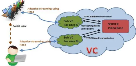
In this system there is a video cloud(VC) to store all the video from the users. Video cloud is a Cloud server which has the all the advantages of cloud server such as elasticity, security and scalability. All the user data is stored in a Database at cloud server (VB-VideoBase). Each user can access and view the videos from the server. Based on the area or set of users the VC is divided into SubVC(SubVideoCloud). The user then streams the video from this SubVC.
Here the system is basically divided into 3 parts: 1. Social networking
2. Adaptive video streaming 3. TFRC Protocol
To implement this system a social media is developed in order to create users and let them share videos. Sharing or uploading a video indicates that the video is being stored in the Cloud. Another provision is to allow users to view the video with some access privileges. In social media used in the proposed approach, user can upload video and view videos uploaded by their friends. The second term is used for streaming the video adaptively. The method used here is the SVC(Scalable Video Coding) technique. Scalable video coding is based on a bandwidth prediction algorithm for providing better quality of video in situations when the network speed is less.
TFRC protocol is TCP-Friendly rate control protocol is receiver based congestion control mechanism for transfer video in cloud. This protocol has great advantage than TCP transmission in terms of packetloss and through put.
The social network is accessed from the SubVC and Video is streamed from this SubVC. When a user want to view a video it streams from SubVC. The SubVC have a data storage called SubVB (SubVideoBase).The SubVB download the video from VB(Video base in VC) using congestion control mechanism called TFRC-Protocol.
If a lot of users are accessing the video then there is congestion in network and by using this protocol the data is send with less packet loss and hence reduce congestion in network.
Adaptive video streaming uses the latest technology H264/AVC which streams the data with lower bandwidth which allows a user to view the video with no interruption in streaming. Also, most of the video shared by the user is mp4 and HD, the H264 has the flexibility to stream high definition Blu-ray videos.
III. OVERALL ARCHITECTURE
The overall system architecture is as shown in the figure 3.1.
Figure 3.1. Overall System Architecture
A. Overall Working
Video Cloud is a cloud storage in cloud environment and VC have a database called VB (Video Base).The user in our system the user are registered the request is passed to the server program in VC. All users can communicate with the server via a social network , called SubVC (Sub Video Cloud).
© 2014, IJCSMC All Rights Reserved
516
If the video is not available in the subVC, the system checks the server. Finally the video is transferred from the server to the sub VC using TFRC protocol. The video is adaptively streamed and is made available to the user. As the network traffic and the probability of congestion is high, for the transfer from the cloud server to the respective users subVC, the use of TFRC protocol is highly efficient and reduce the packet loss rate.
Further optimization is obtained by prefetching the videos to the Sub VC, based on the past experiences of a particular users action.
The system architecture of TFRC based adaptive video streaming in Cloud contains mainly 3 parts which are: 1.VideoCloud
2. Sub Video Cloud 3.Users
B. VC-Video Cloud
It act as the Cloud server in this scheme. The uploaded videos from all users are stored here. And it has all the advantages of a Cloud both in terms of data storage and processing.
Videocloud (VC) has all the advantages of cloud Server. By using cloud mechanism it is more secure than any other server in internet. To store the videos in VC here use a VideoBase. The video base is the cloud store and can store all videos, the user upload.
C. SubVC- Sub Video Cloud}
SubVC have a SubVB(Sub VideoBase) for area/group of users to store videos temporarily. It is similar to a Server in Cloud environment. Each user in this system communicates with this SubVC.
Here, for users in an area, the VC is divided into SubVC and user streams the video from this. Actually it is Apache server and our social site is implemented in SubVC. The SubVb stores the video from VB and streams using H264.
By using this separate server called SubVC, one can reduce the computation at Cloud server (VC) in web. All our social media is accessed from this subVC but the data are validated and comes from VC. When a user access the site and login into his/her home page the datas related to his profile is coming from VC and this will connect every users from all over the world who is registered into our system.
Each request is passing to VC through this SubVC. So it is not needed to store all the datas of users in one subVC.as every subVC can get all the data from VC. To stream the video with prebuffering the SubVC need to download the video from VB to SubVB using TFRC-Protocol.
D. Users
User(s) who use this system. They can share videos by uploading them to the Cloud and can also download videos shared by friends.
E. Adaptive Video Streaming
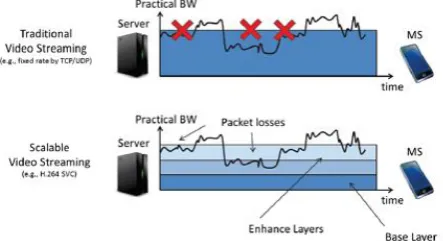
As shown in Fig. 3.2, traditional video streams, especially the ones with fixed bit rates finds it difficult to adapt to the fluctuation of the link quality. If the sustainable link bandwidth is found to varya lot, there is a possibility that the video streaming be terminated frequently due to the packet loss.
SVC has two types of layers: a Base Layer (BL) and some Enhancement Layers (ELs). According to SVC, BL is guaranteed to be delivered. Whenever the link can afford more ELs can be obtained. This will automatically result in a better video quality. The main advantage of using SVC encoding techniques is that the server does not have to worry about the client side or the link quality. Even in the case when some packets are lost, the client is still able to decode the video and display it. But this may still not be bandwidth-efficient. This is due to the presence of unnecessary packet loss. So it is critical to control the SVC-based video streaming at the server side. This control is made possible with the rate adaptation method in order to efficiently utilize the bandwidth.
© 2014, IJCSMC All Rights Reserved
517
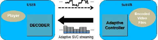
F. H264/AVC
Figure 3.3. Functional structure of the user and the subVC
H.264 is a video compression format also known as MPEG-4 AVC. Originally it was developed for use in high definition systems as well as low resolution portable devices, The factor that distinguishes H.264 from both MPEG-2 and MPEG-4 ASP is that it offers better quality at lower file sizes. It is one of the formats that is supported by both high definition DVD standards.
SVC is a standardized extension of H.264/AVC. If considered conceptually, the design of H.264/AVC consists of both a Video Coding Layer and Network Abstraction Layer . The VCL creates a coded description of the original source content. This data is formatted by the NAL.
1. Network Abstraction Layer (NAL)
The coded video data is first organized into chunks called NAL units. A NAL unit begins with a one-byte header, which signals the type of the data contained in it. The remaining bytes represent what is known as the payload data. NAL units are divided into 2 – VCL NAL units and non-VCL NAL units. The former contain coded slices or coded slice data partitions, while the latter contain associated additional information about the data.
The two major non-VCL NAL units are parameter sets and Supplemental Enhancement Information (SEI). The sequence and picture parameter sets contain information for a video sequence that changes infrequently. SEI messages are not really required in decoding of the samples of a video sequence. They are introduced to provide additional information which can assist the decoding process or related processes like bit stream manipulation or display. The decoding of an access unit will give as output exactly one decoded picture. A set of consecutive access units with certain properties is called a coded video sequence. A coded video sequence thus represents decodable part of a NAL unit bit stream. `
2. Video Coding Layer (VCL)
The VCL of H.264/AVC follows the block-based hybrid video coding method. Although its basic design is very similar to previous video coding standards such as H.261, MPEG-1 Video, H.262 MPEG-2 Video, H.263, or MPEG-4 Visual. H.264/AVC includes new features that enable it to achieve a great improvement in compression efficiency relative to any previous video coding standard .The main difference to previous standards is the largely increased flexibility and adaptability of H.264/AVC.
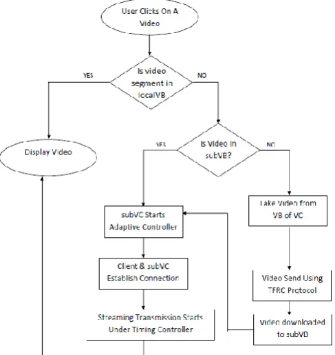
G. Video storage in Adaptive video streaming in cloud
The working of the scheme is described in figure 3.4. The process begins when a user clicks on a video to view it. First it is checked whether the required video is already present in the local VB. This acts like a cache to store some videos for easy download. If the video is present there, then it is displayed directly without further processing.
If the video is not present in the local VB, then the sub VB is checked. Here there are 2 further processing flows.
If the video is present in subVB, then the SubVC begins adaptive controller. The Client establishes a connection and then streaming transmissions begins under a timing controller.
© 2014, IJCSMC All Rights Reserved
518
Figure 3.4. Overall Design Flow
H. TFRC Protocol Implementation
TFRC is used in any Internet environment where the main type of data flow is “unicast”. The congestion that occurs in such environment is controlled using this mechanism[10]. TFRC was designed in such a way that itis almost fair when there is a competition for bandwidth along with TCP flows. However this is the main point of interest and TFRC does not specify a complete protocol. However, when one compare TFRC and TCP, it can be seen that TFRC has much lower variation of throughput over time when compared with TCP. This is the factor that makes TFRC more suitable for applications like telephony or streaming media in which, a relatively smooth sending rate is of critical importance.
There is however a major disadvantage of having smoother throughput than TCP. This is that, even if TFRC is found to compete fairly for bandwidth, it responds rather slower than TCP to the changes that a represent in bandwidth is available.
TFRC is a technically a receiver-based mechanism. The calculation of the congestion control information in the data is done at the receiver and not at the sender. Such a mechanism is well-suited for applications where the sender is a very large server handling many connections simultaneously, and the receiver has comparatively more memory and high processing speed available for computation.
I. Protocol Mechanism
For making its congestion control mechanism practical, TFRC relies on a throughput equation which calculates the sending rate as a function of the parameters by receiver. A loss event is defined as one or more lost packets from a window of data.
Generally speaking, TFRC's congestion control protocol works as follows:
i. The loss event rate is measured by the receiver and this information is send back to the sender.
ii. The sender measure the round-trip time (RTT) using this feedback information.
iii. Using the calculated values of loss event rate and RTT throughput is calculated which gives an acceptable transmit rate.
iv. The sender uses this calculated transmit rate and adjusts its own transmit rate accordingly.
J. TCP Throughput Equation
It should be noted that any realistic equation giving TCP sending rate as a function of parameters from receiver such as loss event rate and RTT is suitable for use in TFRC.. The throughput equation is given in equation 3.1
© 2014, IJCSMC All Rights Reserved
519
Here:
X defines transmit rate in bytes/second.
S refers to packet size measured in bytes.
R is the round trip time .
p is the loss event rate. It has value between 0 and 1.
t_RTO is the TCP retransmission timeout value.
b is the number of packets acknowledged by a single TCP acknowledgement.
IV. PERFORMANCE EVALUATION
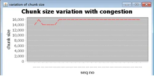
The performance of the system is prominent when a congestion occurs in a network. When the network faces a congestion, the TFRC protocol adapts itself by varying the chunk size, and thus avoiding packet loss. As an evaluation measure, the variation of chunk size is measured and plotted as shown in figure 3.5
Figure 3.5. Chunk size variation with congestion
V. ACKNOWLEDGEMENT
The authors would like to thank the staff and students of Computer Science Department of Viswajyothi College Of Engineering And Technology, Vazhakulam, Kerala for their guidance and support.
REFERENCES
[1] Xiaofei Wang, Min Chen, Ted “Taekyoung” Kwon, Laurence T. Yang and Victor C.M. Leung
'AMES-Cloud: A Framework of Adaptive Mobile Video Streaming and Efficient Social Video Sharing in the
Clouds' IEEE TRANSACTIONS ON CLOUD COMPUTING VOL:15 NO:4 YEAR 2013
[2] YuhengLi ,Yiping Zhang and Ruixi Yuan 'Measurement and Analysis of a Large Scale Commercial
Mobile Internet TV System' , ACM IMC 2011
[3] Heiko Schwarz and DetlevMarpe 'Overview of the SVC Extension of the H.264/AVC Standard' , IEEE
Transactions On Circuits And Systems For Video Technology 2007
[4] Di Niu, Hong Xu, BaochunLi , and Shuqiao Zhao 'Quality-Assured Cloud Bandwidth Auto-Scaling for
Video-on-Demand Applications' ,WPMC 2011
[5] Zixia Huang, Chao Mei1, Li Erran Li and Thomas Woo 'CloudStream: Delivering high-quality
streaming videos through a cloud-based SVC proxy' , IEEE INFOCOM 2011
© 2014, IJCSMC All Rights Reserved