An Omnidirectional Resonator for Wireless Power Transfer
Yangjun Zhang* and Masaki Obata
Abstract—Angular misalignment is an issue for many potential wireless power transfer (WPT) applications. This paper proposes a resonator as an effort to solve this issue. In the beginning, this paper gives an example of quantitative coupling analysis on angular misalignments. Then, it proposes an omnidirectional resonator for electromagnetic coupling WPT system. The proposed resonator is based on the structure of a regular polyhedron. It is constructed of four planar spiral resonators arranged as a regular tetrahedron. The coupling between the proposed resonator and a planar spiral resonator is verified. Both the simulated and measured results show that the coupling coefficient can be kept at a certain level when the omnidirectional resonator rotates around all x, y, and z axes regardless of the orientation of the planar spiral resonator respect to the omnidirectional resonator.
1. INTRODUCTION
Wireless power transfer (WPT) technique is able to provide energy in a cordless way so that it brings new progress and convenience in our life. Electromagnetic induction, coupling, and radiation are three main methods for wireless power transfer [1–3]. The electromagnetic coupling method has the features of high efficiency, low cost, and being able to transfer power in a longer distance than the induction method [2– 4]. In a WPT system of electromagnetic coupling, coupling coefficient between the resonators is a key parameter because the power is transferred via electric and magnetic couplings between transmitting and receiving resonators. Therefore, it is essential to keep the coupling at a certain level for a coupling WPT system. In addition to the coupling coefficient, other parameters including Q value of the resonator, impedance matching, etc. must be designed carefully [5–7].
In a WPT system, the coupling between the resonators depends on many factors such as the structure of resonator, distance and alignment between the resonators and environmental conditions. Among these factors, angular misalignment is an issue for many potential WPT systems. Angular misalignment frequently occurs in WPT systems for mobile electrical device, implant device, flying drone, etc. Many studies have been reported on this issue, and some techniques have been proposed to maintain performance of a WPT system even in an angular misalignment. In previous studies [8–10], a resonator with three orthogonal circular coils was proposed for wireless power transfer regardless of the orientation of the receiver. In [11], a mathematical analysis was given on the 3D omnidirectional wireless power transfer, and the general principle of load detection was addressed. Recently, the size of the resonator with orthogonal coils for implantable devices was reduced to around 1 cubic centimeter [12]. In addition to using the resonator in circular structures mentioned above, a cubic transmitting coil was reported for an omnidirectional magnetic resonant coupling WPT system in [13]. A double 3D resonator with square coils for a quasi-omnidirectional dynamic WPT system was proposed in [14]. In addition to the improvement of the resonator design, other techniques for omnidirectional WPT systems were also studied. For example, a WPT system was proposed based on the multimode of a resonant cavity which efficiently delivered power to nearly all of the areas in a confined 3D volume of space [15]. A
Received 1 May 2019, Accepted 6 July 2019, Scheduled 22 July 2019
* Corresponding author: Yangjun Zhang ([email protected]).
technique of arbitrary magnetic field control was proposed for omnidirectional capsulated endoscope application [16]. In this technique, the transmitter coils were placed in a usual planar PCB board; meanwhile, the magnetic field at the receiver coil was controlled by changing the phase of transmitter switching signal.
Our previous study proposed a 3D spiral resonator which was less influenced by angular misalignment [17]. The proposed 3D resonator was constructed with 3 spirals arranged in a regular triangular prism. The simulated and measured results indicated that the resonator could keep the coupling at a certain level when it rotated around two axes, for example,x andyaxes. However, it was unable to maintain the coupling when it rotated around the thirdz axis [17].
This study is an extension of our previous work reported in [17]. The study proposes an omnidirectional resonator which can keep coupling at a certain level when it rotates around allx,y, and z axes. The proposed omnidirectional resonator is verified by the simulated and measured results. The paper is organized in the following four sections. Section 2 quantitatively indicates that the coupling is very weak in angular misalignments for the helical resonators. Section 3 proposes an omnidirectional resonator based on a regular tetrahedron. Section 4 presents the simulated and measured results of coupling between the proposed omnidirectional resonator and a planar spiral resonator when the omnidirectional resonator rotates around x,y, andz axes. Section 5 gives a conclusion.
2. COUPLING DEPENDENCE ON ALIGNMENT ANGLE
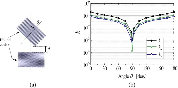
The spiral and helical resonators are two basic structures used in WPT systems. It is necessary to understand the magnetic and electric coupling components for these two basic resonators. In our previous study, we analyzed the dependence of coupling on alignment angle for spiral resonator and showed that the magnetic coupling component was 0 when two spiral resonators were in perpendicular positions [17]. In this study, we give an example of the coupling analysis on helical resonators to indicate the coupling dependence on the alignment angle. Figure 1 shows the calculated coupling coefficients k, and magnetic and electrical componentskm and ke as the functions of the rotating angle. Here,k,km,
and ke are calculated by the overlap integral method shown in the following equation [17–20]
k=
V
(μH∗1·H2−εE∗1·E2)dV √
W1W2
=|km−ke|, (1)
where E1, E2 are the electric fields of two resonators before coupling, respectively; H1, H2 are the magnetic fields of two resonators before coupling, respectively; and W1, W2 are the energies of two
(a) (b)
30 60 90 120 150 180
0
10-5
10-4
10-3
10-2
10-1
100
k
Angle T [deg.]
k km -ke d
T
Helical coils
resonators before coupling, respectively.
It can be seen that the coupling coefficientk, and magnetic and electrical coupling componentskm
and ke become significantly weak when the alignment angle is near 90◦, although the coupling between
the helical resonators depends on the resonator structure and relative turn direction of two coils. For an electromagnetic coupling WPT system, it is necessary to keep coupling coefficient at a certain level even in an angular misalignment.
3. OMNIDIRECTIONAL RESONATOR
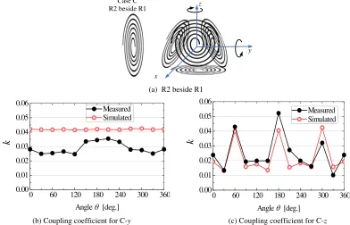
To solve the issue of angular misalignment, one method is to use a resonator with omnidirectional property. The 3D resonator proposed in our previous study shown as Figure 2 partially overcomes this issue. It has a structure based on a regular triangular prism [17]. If a coordinate system as Figure 2(a) is referred, the 3D resonator can keep the coupling at a certain level when it rotates around x and y axes. However, it is unable to maintain the coupling when it rotates around z axis. Our successive study reported in this paper proposes a real omnidirectional resonator.
(a) (b)
z x y
Rx
Tx
Figure 2. (a) 3D spiral resonator proposed in our previous study. (b) The prototype of 3D resonator [17].
A resonator in a sphere shape is obviously an omnidirectional resonator independent ofx, y, and z rotations. As illustrated in Figure 3(a), there is no variation when the sphere rotates with respect to the transmitting element. However, a resonator in sphere shape has a complicated structure and is difficult to manufacture.
(a) (b)
Tx
Rx
Figure 3. (a) A resonator in sphere shape is an omnidirectional resonator. (b) Five convex regular polyhedrons.
that in angular misalignments, the stable coupling coefficient is easily obtained for a resonator with many faces, because a resonator having many faces nearly approaches a resonator in a sphere shape. A resonator in a cube shape also has a simple structure. However, electromagnetic field of the resonators in two parallel faces may conceal each other strongly, resulting a total weak coupling coefficient.
In this study, we choose a regular tetrahedron as the structure of the omnidirectional resonator. The advantage of this structure is that a tetrahedron has fewer faces (four faces) and a simpler structure, and therefore it is easy to fabricate. Additionally, the four faces in a regular tetrahedron are not parallel to each other. This can avoid the cancelation effect of electromagnetic fields of spiral coils.
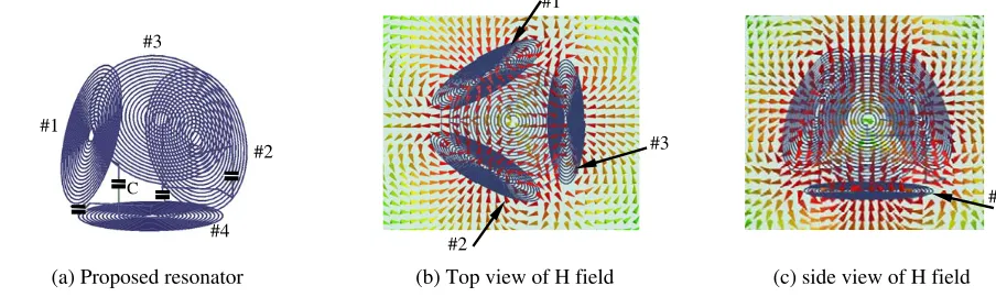
Figure 4(a) shows the proposed omnidirectional resonator. It is constructed of four planar spiral resonators arranged in four faces of a regular tetrahedron. The four planar spiral resonators have an identical structure. They are connected by 4 lumped capacitors. Capacitor is used to adjust resonant frequency. The four spiral resonators are so arranged that the resonator has a symmetric field distribution. Figures 4(b) and 4(c) show the simulated magnetic field for the proposed omnidirectional resonator. It can be seen that the magnetic components perpendicular to the spirals are all in the directions toward the inside of the resonator at this phase. Such a balanced magnetic field avoids the fluctuation of coupling in the resonator rotation.
(a) Proposed resonator (b) Top view of H field (c) side view of H field
#1
#2
#3
#4 #1
#2
#4 #3
C
Figure 4. (a) Proposed omnidirectional resonator based on a regular tetrahedron. Resonant frequency f = 15.17 MHz. Four spirals have an identical structure. Structure of spiral: Wire diameterdw= 1 mm, out diameter D = 120 mm, turn number T = 17 and pitch p = 2.24 mm. C = 8.0 pF. (b) Top view of simulated magnetic field of the proposed resonator. (c) Side view of simulated magnetic field of the proposed resonator.
4. COUPLING COEFFICIENT VERIFICATION
In this section, the coupling coefficient is verified when the omnidirectional resonator rotates. The values of coupling coefficient in different alignments are determined by using both simulation and measurement methods. In both methods, one resonator is the proposed omnidirectional resonator (R1), and the other is a planar spiral resonator (R2) which has the same resonant frequency as the proposed omnidirectional resonator.
4.1. Coupling When the Omnidirectional Resonator Rotates
z
y
Case A R2 below R1
x
Case B R2 above R1 Case C
R2 beside R1
Figure 5. Coupling analysis for the omnidirectional resonator rotation.
It can be noted that these three positions are included in above 9 states, although it is complicated to describe all alignments.
The nine states are named as A-x, A-y, A-z, B-x, B-y, B-z, C-x, C-y, and C-z in the following. It can be understood that the coupling of B-xis the same as A-x, B-ysame as A-y, and C-xsame as A-y (or B-y). Therefore, coupling analysis actually includes six states, A-x, A-y, A-z, B-z, C-y, and C-z.
4.2. Evaluation Methods of the Coupling Coefficient
The coupling coefficient is determined by using both simulation and measurement methods. In the simulation, the coupling coefficient k is calculated by the frequency method [21] using the following equation
k= 2(fH−fL)
(fH+fL) , (2)
wherefH and fLare the higher and lower split frequencies of the coupled resonators, respectively. The
resonant frequencies of R1 and R2 resonators are set equal originally. In the simulation, R2 is designed to resonate at 15.17 MHz as the resonant frequency of R1 is 15.17 MHz. The parameters of the adjusted structure of R2 are wire diameterdw= 1 mm, spiral out diameterD= 170 mm, turn numberT = 19.88, and pitchp= 3.0 mm.
In the experiments, the split frequenciesfH and fLare measured by the experimental setup shown
in Figure 6, then k is calculated by Equation (2). The experimental setup in principle is the same as the setup reported in [2]. The omnidirectional resonator (R1) is manually rotated with respect to the planar spiral resonator (R2) in a step of 30◦. In each alignment, the shortest distance between R1 and R2 is adjusted to keep at 30 mm to correspond to the distance in the simulation. The two loop coils are single loop cooper coils to excite and receive the electromagnetic field, and they are connected to the input and output of a network analyzer (Omicron@ VNA Bode 100). The split frequenciesfH and fL
are read from the measured curves ofS11 orS21.
d
Network Analyzer Loop coil
Loop coil
Figure 7(a) shows a prototype of omnidirectional resonator made in our laboratory. It is fabricated with the same structure adopted in the simulation. The measured resonant frequency is 13.01 MHz, which is lower than the frequency obtained in the simulation. This difference is considered to be caused by dispersion of capacitance and difference between the model of fabrication and simulation. R2 resonator in the experiment is designed to resonate at 13.01 MHz. The parameters of R2 in the
(a) (b)
0 50 100 150 200 250 300 350 12.98
13.00 13.02 13.04 13.06 13.08 13.10 13.12
Resonant frequency [MHz
]
Distance between the loop and the resonator [mm]
Planar spiral
Omni directional resonator
Figure 7. (a) The prototype of the omnidirectional resonator. Four spirals have an identical structure and the structure is the same with that adopted in the simulation. (b) The measured resonant frequencies of the omnidirectional resonator and a conventional planar spiral resonator.
(a) The planar spiral resonator (R2) is below the omnidirectional resonator (R1)
(b) Coupling coefficient for A-x
(c) Coupling coefficient for A-y (d) Coupling coefficient for A-z
60 120 180 240 300 360
0 0.00 0.02 0.04 0.06 0.08 0.10
k
Angle T [deg.]
Measured Simulated z
y
Case A R2 below R1 x
60 120 180 240 300 360
0 0.00 0.02 0.04 0.06 0.08 0.10
k
Angle T [deg.]
Measured Simulated
60 120 180 240 300 360
0 0.00 0.02 0.04 0.06 0.08 0.10
k
Angle T [deg.]
Measured Simulated
experiment are wire diameter dw= 1 mm, spiral out diameter D= 170 mm, turn numberT = 24, and pitchp= 2.5 mm. The measured resonant frequencies of R1 and R2 resonators are shown in Figure 7(b).
4.3. Results of Coupling Coefficients
As mentioned in Subsection 4.1, the coupling is analyzed on six states of A-x, A-y, A-z, B-z, C-y, and C-z. Figures 8, 9, and 10 show the simulated and measured results on these six states. It is indicated that the measured and simulated results generally agree well. The coupling coefficient is kept at a certain level when the resonator of regular tetrahedron rotates in all directions. For the simulated and measured resonator models, the total coefficient is above 0.01 in all alignments.
(a) R2 above R1 (b) Coupling coefficient for B-z
60 120 180 240 300 360 0
0.00 0.01 0.02 0.03 0.04 0.05 0.06
k
Angle T [deg.] Measured Simulated
z
y
x
Case B R2 above R1
Figure 9. The simulated and measured coupling coefficient as functions of rotating angle when the planar spiral resonator is set above the omnidirectional resonator.
(a) R2 beside R1
(b) Coupling coefficient for C-y (c) Coupling coefficient for C-z
60 120 180 240 300 360
0 0.00 0.01 0.02 0.03 0.04 0.05 0.06
k
Angle T [deg.]
Measured Simulated
60 120 180 240 300 360
0 0.00 0.01 0.02 0.03 0.04 0.05 0.06
k
Angle T [deg.]
Measured Simulated
z
y
x Case C R2 beside R1
5. CONCLUSION
This study is an extension of our previous study to address the issue of angular misalignment in WPT systems. First, an example of quantitative coupling analysis for helical resonators is given. The quantitative coupling analysis shows that the magnetic and electric coupling components become weak in an angular misalignment. Then, this paper proposes an omnidirectional resonator for electromagnetic coupling WPT system. The proposed resonator is based on the structure of a regular polyhedron. It is constructed of four planar spiral resonators arranged as a regular tetrahedron. The coupling between the proposed resonator and a planar spiral resonator is analyzed. The angular alignments include the arrangements that the omnidirectional rotates aroundx,y, andzaxes when the planar spiral resonator is set below, beside, and above the omnidirectional resonator, respectively. Both the simulated and measured results show that the coupling coefficient can be stabilized at a certain level when the proposed resonator rotates around allx,y, andzaxes, regardless the planar spiral resonator location with respect to the omnidirectional resonator. The optimum design for the proposed omnidirectional resonator will be studied in our future works.
REFERENCES
1. Tesla, N., “Transmission of electrical energy without wire,”Elect. World Eng., Mar. 5, 1904, Online Available: ww.tfcbooks.com/tesla/.
2. Kurs, A., A. Karalis, R. Moffatt, J. D. Joannopoulos, P. Fisher, and M. Soljacic, “Wireless power transfer via strongly coupled magnetic resonances,” Science, Vol. 317, 83–86, Jul. 2007.
3. Shonohara, N.,Wireless Power Transfer via Radiowaves, ISTE Ltd and John Wiley & Sons, Inc., 2014.
4. Awai, I., “Magnetic resonant wireless power transfer,” Nikkei Electronics, 2011 (in Japanese). 5. Ohira, T., “Maximum available efficiency formulation based on a black-box model of linear two
port power transfer systems,”IEICE Electronics Express, ELEX, Vol. 11, No. 13, 1–6, #20140448, Jun. 2014.
6. Zhang, J., X. Yuan, C. Wang, and Y. He, “Comparative analysis of two-coil and three-coil structures for wireless power transfer,”IEEE Transactions on Power Electronics, Vol. 32, No. 1, 341–352, 2017. 7. Tierney, B. B. and A. Grbic, “Design of self-matched planar loop resonators for wireless nonradiative power transfer,”IEEE Transactions on Microwave Theory and Techniques, Vol. 62, No. 4, 909–919, 2014.
8. Jonah, O., S. V. Georgakopoulos, and M. M. Tentzeris, “Orientation insensitive power transfer by magnetic resonance for mobile devices,”Proc. IEEE Wireless Power Transfer, Vol. 15/16, 5–8, Perugia, Italy, 2013.
9. Ng, W. M., C. Zhang, D. Lin, and S. R. Hui, “Two-and three-dimensional omnidirectional wireless power transfer,”IEEE Transactions on Power Electronics, Vol. 29, No. 9, 4470–4474, 2014. 10. Zhang, C., D. Lin, and S. Y. Hui, “Basic control principles of omnidirectional wireless power
transfer,”IEEE Trans. Power Electron., Vol. 31, No. 7, 5215–5227, Jul. 2016
11. Lin, D., C. Zhang, and S. Y. Ron Hui, “Mathematic analysis of omnidirectional wireless power transfer — Part-II three-dimensional systems,” IEEE Transactions on Power Electronics, Vol. 32, No. 1, 613–624, 2017.
12. Pacini, A., F. Benassi, D. Masotti, and A. Costanzo, “Design of a miniaturized omni-directional RF-to-dc IR-WPT,”2018 IEEE Wireless Power Transfer Conference (WPTC), 1–4, 2018.
13. Nam, H.-V. and C. Seo, “Analytical and experimental investigations of omnidirectional wireless power transfer using a cubic transmitter,” IEEE Transactions on Industrial Electronics, Vol. 65, No. 2, 1358–1366, 2018.
15. Chabalko, M. J., and A. P. Sample, “Three-dimensional charging via multimode resonant cavity enabled wireless power transfer,” IEEE Transactions on Power Electronics, Vol. 30, No. 11, 6163– 6173, 2015.
16. Inada, Y., T. Kawajiri, U. Takeda, and H. Ishikuro, “Arbitrary magnetic field control technique by multi-coil transmitter voltage phase shifting for omni-directional free-positioning magnetic resonance wireless power delivery,”48th European Microwave Conference (EuMC), 186–189, 2018. 17. Zhang, Y., T. Yoshikawa, and T. Kitahara, “Magnetic and electric coupling analysis for angular misalignment of spiral resonators in WPT systems,” Progress In Electromagnetics Research M, Vol. 76, 1–8, 2018.
18. Awai, I., “New expressions for coupling coefficient between resonators,” IEICE Trans. Electron., Vol. 88C, No. 12, 2295–2301, Dec. 2005.
19. Awai, I., S. Iwamujra, H. Kubo, and A. Sanada, “Separation of coupling coefficient between resonators into electric and magnetic contributions,” IEICE, Vol. 88-C, No. 12, 1033–1039, 2005 (in Japanese).
20. Zhang, Y., T. Yoshikawa, and I. Awai, “Analysis of electric and magnetic coupling components for spiral resonators used in wireless power transfer,” 2014 Asia-Pacific Microwave Conference, 1366–1368, 2014.
![Figure 2.(a) 3D spiral resonator proposed in our previous study.(b) The prototype of 3Dresonator [17].](https://thumb-us.123doks.com/thumbv2/123dok_us/1967978.1259617/3.612.133.485.502.603/figure-spiral-resonator-proposed-previous-study-prototype-dresonator.webp)