User's Guide
Guide de l’utilisateur
Bedienungsanleitung
En
This manual and the software and firmware described in it are copyrighted by Wyse Technology Inc. You may not reproduce, transmit, transcribe, store in a retrieval system, or translate into any language or computer language, in any form or by any means, electronic, mechanical, magnetic, optical, chemical, manual or otherwise, any part of this publication without the express permission of Wyse Technology Inc.
Trademarks WYSE is a registered trademark. Winterm, WT2000, WT2300, WT2500, and WT2700 are trademarks of Wyse Technology Inc.
Cirrus Logic is a trademark of Cirrus Logic, Inc.
ICA 3 is a trademark of Citrix Systems, Inc.
Microsoft and Windows are registered trademarks of Microsoft Corporation.
All other products are trademarks and/or registered trademarks of their respective companies.
The Energy Star emblem does not represent endorsement of any product or service.
Specifications subject to change without notice.
Restricted Rights Legend
Use, duplication, or disclosure by the Government is subject to restrictions as set forth in subparagraph (c)(1)(ii) of the Rights in Technical Data and Computer Software clause at 252.227-7013.
Related Publications The following publications can be ordered from Wyse Technology: Winterm Terminal Installation Guide
Winterm Terminal Connectivity Guide
For availability, pricing, and ordering information in the United States and Canada, call 1-800-GET-WYSE (1-800-438-9973). In all other countries, contact your sales representative.
WYSE TECHNOLOGY INC. 3471 North First Street
En
gli
s
h
designed to provide reasonable protection against harmful interference in a residential installation. This equipment generates, uses, and can radiate radio frequency energy and, if not installed and used in accordance with the instructions, may cause harmful interference to radio communications. However, there is no guarantee that interference will not occur in a particular installation. If this equipment does cause harmful interference to radio or television reception, which can be determined by turning the equipment off and on, the user is encouraged to try to correct the interference by one or more of the following measures:
◆ Reorient or relocate the receiving antenna.
◆ Increase the separation between the equipment and the receiver.
◆ Connect the equipment into an outlet on a circuit different from that to which the receiver is connected.
◆ Consult the dealer or an experienced radio/TV technician for help.
◆
Caution Changes or modifications not covered in this manual must be approved in writing by the manufacturer’s Regulatory Engineering department. Changes or modifications made without written approval may void the user’s authority to operate the equipment.❖
Note Grayscale terminals meet only Class A requirements.Canadian DOC Notice This digital apparatus does not exceed the Class B limits for radio noise emissions from digital apparatus set out in the Radio Interference Regulations of the Canadian Department of Communications.
❖
Note Grayscale terminals meet only Class A requirements.Le présent appareil numérique n’émet pas de bruits radioélectriques dépassant les limites applicables aux appareils numériques de la classe A prescrites dans le Règlement sur le brouillage radioélectrique édicté par le Ministére des Communications du Canada.
❖
Remarque Les terminaux à échelle de gris sont conformes aux spécifications de la classe A uniquement.IEC/EN Notice This product conforms to the requirements of IEC 950 and EN 60950. This product conforms to requirements of EN 55022 for Class B equipment.
❖
Note Grayscale terminals do not meet EN55022 Class B requirements.License Agreement YOU SHOULD CAREFULLY READ THE FOLLOWING TERMS AND CONDITIONS BEFORE USING THIS EQUIPMENT WHICH CONTAINS SOFTWARE IN A NON-VOLATILE FORMAT AND CERTAIN OTHER INTELLECTUAL PROPERTY (HEREAFTER “FIRMWARE”). USING THIS EQUIPMENT INDICATES YOUR ACCEPTANCE OF THE FOLLOWING TERMS AND CONDITIONS.
Grant You may use the Firmware in or in conjunction with the Equipment as provided to You. You may transfer ownership of the Equipment, including the right to use the Firmware to another party so long as that party agrees to accept these terms and conditions.
YOU MAY NOT USE, COPY, MODIFY, TRANSLATE OR TRANSFER THE FIRMWARE, OR MODIFICATION THEREOF, IN WHOLE OR IN PART, EXCEPT AS EXPRESSLY PROVIDED FOR IN THIS LICENSE. YOU MAY NOT DECOMPILE, REVERSE ENGINEER OR OTHERWISE DECODE OR ALTER THE SOFTWARE CONTAINED IN THE FIRMWARE.
Limited Software Warranty and Disclaimer
WYSE warrants that, for a period of ninety (90) days from the date of shipment, the Firmware will, under normal use, be free from defects in materials and workmanship in the EPROM (or similar storage device). The foregoing warranty shall not apply to any Firmware which has been used in violation of this Agreement. During this limited warranty period WYSE will provide support by phone on a best-efforts basis. WYSE may, in addition to the above, replace any defective Firmware with a functionally equivalent product. The foregoing shall be Your exclusive remedy for any breach of warranty hereunder. You assume responsibility for choosing the Equipment containing the Firmware to achieve your intended results, and for the installation, use and results obtained from the Equipment and Firmware.
EXCEPT FOR THE ABOVE EXPRESS LIMITED WARRANTIES, WYSE MAKES AND YOU RECEIVE NO WARRANTIES ON THE FIRMWARE, EXPRESS, IMPLIED, OR STATUTORY, OR IN ANY OTHER PROVISION OF THIS AGREEMENT OR COMMUNICATION WITH YOU, AND WYSE DISCLAIMS ANY IMPLIED WARRANTIES OF MERCHANTABILITY, NON-INFRINGEMENT AND FITNESS FOR ANY PARTICULAR PURPOSE. WYSE DOES NOT WARRANT THAT THE FUNCTIONS CONTAINED IN THE PRODUCT WILL MEET YOUR REQUIREMENTS OR THAT THE OPERATION WILL BE UNINTERRUPTED OR ERROR FREE. SOME STATES DO NOT ALLOW LIMITATIONS ON HOW LONG AN IMPLIED WARRANTY LASTS SO THE ABOVE LIMITATION MAY NOT APPLY TO YOU. THIS WARRANTY GIVES YOU SPECIFIC LEGAL RIGHTS. YOU MAY ALSO HAVE OTHER RIGHTS WHICH VARY FROM STATE TO STATE.
Limit of Liability UNDER NO CIRCUMSTANCES SHALL WYSE BE LIABLE FOR LOSS OF DATA, COST OF COVER, OR ANY INCIDENTAL OR CONSEQUENTIAL DAMAGES, HOWEVER CAUSED AND ON ANY THEORY OF LIABILITY. THESE LIMITATIONS SHALL APPLY EVEN IF WYSE OR ITS RESELLER HAS BEEN ADVISED OF THE POSSIBILITY OF SUCH DAMAGES, AND
NOTWITHSTANDING ANY FAILURE OF ESSENTIAL PURPOSE OF ANY LIMITED REMEDY PROVIDED HEREIN.
YOU AGREE THAT THESE ARE THE ONLY APPLICABLE TERMS OF AGREEMENT BETWEEN US COVERING FIRMWARE AND THAT THEY SUPERSEDE ANY OTHER COMMUNICATIONS (ORAL OR WRITTEN) BETWEEN US RELATING TO THE FIRMWARE.
U.S. Government Restricted Rights
En
gli
s
h
Overview
Introduction . . . v
About This Guide. . . vi
Guide Conventions . . . vi
Windows Keystrokes . . . .vii
1
Communications Setup
2
Administrator and User Functions
Administrator and Terminal User Accounts. . . .2-1 Security Properties Sheet . . . .2-2 Adding Terminal User Accounts . . . .2-3 Modifying Terminal User Accounts . . . .2-5 Deleting Terminal User Accounts . . . .2-7 Auto-Connections . . . .2-8
A
Serial and Parallel Port Pin Assignments
B
Modem Initialization Strings
C
Troubleshooting
List of Figures
1-1 Connections Dialog Box . . . .1-1 1-2 Welcome Dialog Box . . . .1-4 1-3 Options Dialog Box. . . .1-5 1-4 Connection Setup Dialog Box . . . .1-8 1-5 Connection Properties Dialog Box . . . .1-10 1-6 Serial Settings Dialog Box . . . .1-14 1-7 Serial Settings with Modems Dialog Box . . . .1-17 1-8 Security/Scripts Dialog Box . . . .1-19 1-9 Copy Connection Dialog Box . . . .1-21 1-10 Delete Dialog Box. . . .1-22 1-11 Options Dialog Box. . . .1-24 1-12 Printer/Aux Properties Sheet . . . .1-26 1-13 Com1 Serial Printer Settings Dialog Box . . . .1-28 1-14 Display Properties Sheet . . . .1-31
2-1 Security Properties Sheet. . . .2-2 2-2 Add User Account Dialog Box . . . .2-3 2-3 Modify User Account Dialog Box . . . .2-5 2-4 Delete Dialog Box. . . .2-7 2-5 Autoconnect Message Dialog Box . . . .2-8 2-6 Options Dialog Box. . . .2-9
En
gli
s
h
List of Tables
1 Conventions . . . vi 2 Windows Keystrokes . . . .vii
1-1 Connections Dialog Box Functions . . . .1-2 1-2 Welcome Dialog Box Functions . . . .1-4 1-3 Options Dialog Box Functions . . . .1-6 1-4 Connection Setup Functions . . . .1-9 1-6 Serial Settings Dialog Box Functions . . . .1-15 1-7 Modem Parameters . . . .1-18 1-8 Sample Script . . . .1-20 1-9 Terminal Properties Sheet Functions . . . .1-25 1-10 Printer/Aux Properties Sheet Functions . . . .1-27 1-11 Serial Printer Settings Dialog Box Functions . . . .1-29 1-12 Aux Handshake Modes . . . .1-30 1-13 Display Properties Sheet Functions . . . .1-32
2-1 Add User Account Field Descriptions. . . .2-4 2-2 Modify User Account Fields . . . .2-6 2-3 Options Dialog Box Fields . . . .2-9
En
gli
s
h
Overview
Introduction
Windows NT applications servers use the ICA 3.X (Intelligent Console Architecture) protocol to communicate with each terminal in a network. This brings a full range of Microsoft Windows applications such as desktop publishing, word processing, database management, email, presentation, and financial applications to the terminal desktop.An operating system supporting the ICA 3.X protocol must be installed on a Windows NT server before a terminal can communicate with that server. Consult your Windows NT applications documentation for details.
Your windows terminal is designed to communicate with
Windows NT applications servers in either an intranet (within a company) environment, or with other open computing environments using legacy mainframe/large-scale host systems.
About This Guide
The Winterm Terminal User’s Guide consists of the following sections: ◆ Chapter 1, “Communications Setup,” explains how to configure theterminal for communication with a Windows NT applications server. The chapter includes instructions for setting up the terminal’s communications ports for direct, modem, or printer connections.
◆ Chapter 2, “Administrator and User Functions,” explains system administration functions. The chapter includes instructions for enabling the terminal’s security and auto-connect features. Instructions for setting up and modifying terminal user accounts are also available here.
◆ Appendix A, “Serial and Parallel Port Pin Assignments,” provides illustrations showing serial and parallel cable pin-outs between the terminal and a Windows NT applications server.
◆ Appendix B, “Modem Initialization Strings,” lists by modem type the terminal’s default modem initialization strings.
◆ Appendix C, “Troubleshooting,” provides a guide for troubleshooting the terminal.
Guide
Conventions
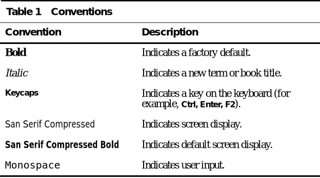
Table 1 lists the conventions used in this document for text formats.
Table 1 Conventions
Convention Description
Bold Indicates a factory default.
Italic Indicates a new term or book title.
Keycaps Indicates a key on the keyboard (for
example, Ctrl, Enter, F2).
San Serif Compressed Indicates screen display.
San Serif Compressed Bold Indicates default screen display.
En
gli
s
h
Windows
Keystrokes
Standard Microsoft Windows keystrokes are supported by the terminal for all Windows applications. These keystrokes are useful if your mouse fails, or if you are not installing a mouse when you set up the terminal. Table 2 lists the alternative keystrokes.
Table 2 Windows Keystrokes
Keystroke Description
Alt Use this key, with an underlined alphanumeric character, to invoke a property sheet or command (i.e. Alt P to invoke the Printer Options from the
Options dialog box).
Tab This key moves the cursor from one field to the next, within a dialog box or property sheet.
Shift Tab This key sequence moves the cursor from one field to the previous, within a dialog box or property sheet.
En
gli
s
h
1
Communications Setup
Chapter 1 explains how to configure this terminal to communicate with a Windows NT applications server via the terminal’s serial port.
❖
Note The server software should be running properly on your applications server. If it is not, stop here and refer to your applications server’sdocumentation for help.
Connections
Dialog Box
The Connections dialog box is the main dialog box for the user interface. It is the first screen to appear after the terminal is turned on. From Connections,
you can log onto a server and configure communications settings and terminal options.
The Connections dialog box also contains the command buttons for the
Connect and Logout functions, and the Options, Setup, About, and Network
dialog boxes. Figure 1-1 shows the Connections dialog box.
❖
Note During a connection, or while making a connection, press the Ctrl + Brkkey to abort a server connection.
❖
Note When networking support is installed on your terminal, the Networkscommand button appears below the About command button in the Connections
dialog box (Figure 1-1). Clicking on this command button invokes the terminal’s network options. Refer to the terminal’s connectivity guide for more network details.
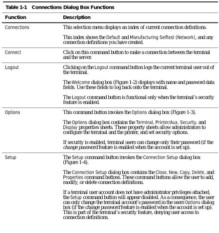
Table 1-1 describes each function in the Connections dialog box.
Table 1-1 Connections Dialog Box Functions
Function Description
Connections This selection menu displays an index of current connection definitions.
This index shows the Default and Manufacturing Selftest (Network), and any connection definitions you have created.
Connect Click on this command button to make a connection between the terminal and the server.
Logout Clicking on the Logout command button logs the current terminal user out of the terminal.
The Welcome dialog box (Figure 1-2) displays with name and password data fields. Use these fields to log back onto the terminal.
The Logout command button is functional only when the terminal’s security feature is enabled.
Options This command button invokes the Options dialog box (Figure 1-3).
The Options dialog box contains the Terminal, Printer/Aux, Security, and
Display properties sheets. These property sheets allow administrators to configure the terminal and the printer, and set security options.
If security is enabled, terminal users can change only their password (if the change password feature is enabled when the account is set up).
Setup The Setup command button invokes the Connection Setup dialog box (Figure 1-4).
The Connection Setup dialog box contains the Close, New, Copy, Delete, and
Properties command buttons. These command buttons allow the user to add, modify, or delete connection definitions.
En
gli
s
h
About Click on this command button to open the About dialog box.
The About dialog box contains copyright, revision, and hardware configuration information.
Network Click on the Network command button to invoke the Networks dialog box.
The Networks dialog box contains the OK, Cancel, Hosts, and About
command buttons. These command buttons allow the user to add and delete host connections from the Network Hosts Table. This box also contains the
TCP/IP group box and the MAC Address field. Table 1-1 Connections Dialog Box Functions, Continued
Welcome Dialog
Box
Figure 1-2 shows the Welcome dialog box. The Welcome dialog box prompts the user for a name and a password. To log back onto the terminal, enter your name and password in the Name and Password fields.
The Welcome dialog box is invoked by clicking on the Logout command button in the Connections dialog box (Figure 1-1).
❖
Note The Welcome dialog box is only visible when security is enabled.Figure 1-2 Welcome Dialog Box
Table 1-2 describes each function in the Welcome dialog box.
Table 1-2 Welcome Dialog Box Functions
Function Description
Name The Name data field is used to enter the username of the terminal user.
Password The Password data field is used to enter the password of the terminal user.
En
gli
s
h
Options Dialog
Box
Figure 1-3 shows the Options (user) dialog box. The Options dialog box is the only option available to a user account, through the Options command button in the Connections dialog box, or through the interruption of an Autoconnect session. This feature lets the user to change only the local terminal password, in the New Password data field, in the Local Password group box. In addition, if Autoconnect connection is associated with this account, the server password in that connection can also be changed.
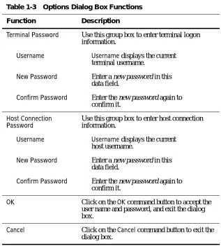
Table 1-3 describes the functions of the Options dialog box.
❖
Note New Password and Confirm Password do not change the host password. Table 1-3 Options Dialog Box FunctionsFunction Description
Terminal Password Use this group box to enter terminal logon information.
Username Username displays the current terminal username.
New Password Enter a new password in this data field.
Confirm Password Enter the new password again to confirm it.
Host Connection Password
Use this group box to enter host connection information.
Username Username displays the current host username.
New Password Enter a new password in this data field.
Confirm Password Enter the new password again to confirm it.
OK Click on the OK command button to accept the user name and password, and exit the dialog box.
En
gli
s
h
Making a Default
Connection
The following instructions describe how to make a connection to a server using the default settings:
1 Select Default from the Connections list.
2 Click on the Connect command button.
3 Enter your user name and password, in the Username and Password fields.
4 Click on OK to accept the connection.
The terminal will attempt a connection according to the factory default settings.
❖
Note Press Ctrl + Break to cancel the default connection attempt.The Default
Connection Definition
When you turn the terminal on, the Connections dialog box appears
(Figure 1-1), displaying a list of connections. A default connection is provided in this list. The following are the factory-preset default settings for the default connection:
◆ Serial port communications set to Com1 direct
◆ Baud rate set at 115,200
◆ Handshaking set to Hardware
◆ Hardware flow controls set to DTR Always On (enabled) and RTS Always On (disabled)
◆ Receive buffer set to RTS Off
◆ Transmit data set to CTS On
These factory-default settings can be modified.
❖
Note The terminal security feature is disabled at the factory. This feature is not active when the terminal is first turned on. This means that administrator and user accounts are not defined. Anyone using the terminal can log onto a server. If terminal security is required, it must be enabled from theMaking a Terminal
Connection
The terminal uses connection definitions to log into a Windows NT
applications server. “Making a Terminal Connection” explains how to create and modify connection definitions.
Two types of serial connections are supported by the terminal—direct and modem. Direct connections are made via a serial cable connecting the terminal to a server. Modem connections are made modem-to-modem via telephone lines, from the terminal to a server. These connectors are on the back panel, and are easily accessible.
The Connection Setup dialog box (see Figure 1-4) is invoked by clicking on the Setup command button in the Connections dialog box (Figure 1-1).
Figure 1-4 Connection Setup Dialog Box
❖
Note The Connection Setup dialog box allows you to create newEn
gli
s
h
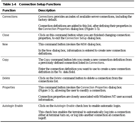
Table 1-4 describes the functions in the Connection Setup dialog box.
\
Table 1-4 Connection Setup Functions
Function Description
Connections Connections provides an index of available server connections, including the factory default.
Connection definitions are added to this list, after defining their properties in the Connection Properties dialog box (Figure 1-5).
Close Click on this command button when you are finished changing connection properties, to exit the Connection Setup dialog box.
New This command button invokes the NEW dialog box.
In the New dialog box, information is entered to create new connection definitions.
Copy The Copy command button lets you create a new connection definition from a previously defined connection listed in Connections.
Enter the connection definition you want to use to create a new connection definition in the To: data field.
Delete Click on the Delete command button to delete a connection from the connections list.
Properties This command button invokes the Connection Properties dialog box (Figure 1-5), allowing the user to modify a connection.
Connection properties are closely associated with Windows NT user account information.
Autologin Enable Click on the Autologin Enable check box to enable automatic login.
Creating and Modifying Connections
The Connection Properties dialog box will allow the user to create or modify connection definitions. Figure 1-5 shows the Connection Properties dialog box. To create or modify a connection definition, use either the New, Copy or
Properties command buttons.
This dialog box is invoked by:
1 Clicking on the Setup command button in the Connections dialog box.
2 Clicking on the New command button in the Connection Setup dialog box.
Figure 1-5 Connection Properties Dialog Box
❖
Note Radio buttons that appear in the Communication group box inEn
gli
s
h
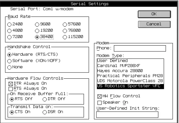
Table 1-5 describes the functions in the Connection Setup dialog box.
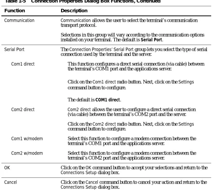
Table 1-5 Connection Properties Dialog Box Functions
Function Description
Description Enter the name of the connection in this data field.
The name that you are creating is unique to, and descriptive of, the
connection. For example, a connection that is configured to log directly into Microsoft Word for Windows could be named msword4windows. Username Enter the Windows NT user account name that the terminal will log into.
The terminal needs this user name to begin a session.
It must be a valid user name on the target Windows NT applications server.
If this field is left blank, the user will be prompted for a user name before logging into the account. Administrators may want to leave this field and the
Domain and Password fields empty, so that the server will always prompt for a user name.
Domain Enter the Windows NT applications server’s domain name.
If this field is left blank, the server will prompt the user for a domain name when logging into the account.
Password Enter the Windows NT user account password in this data field.
If this data field is left blank, the user will be prompted for the password before the terminal allows access to the server. Passwords are encrypted in the terminal.
Command Line The Command Line field is used to enter executable commands.
These commands place the user at log on in an application such as Microsoft Word or Excel. A command line entry could look like this:
C:\WINWORD\WINWORD.EXE
Working Directory Enter the directory path where you want your work to be saved.
The following path identifies the directory where MSWord files are located:
C:\WINWORD\DOC
Sound Enable Click on this box if you want the terminal to beep when a Windows NT event occurs.
Communication Communication allows the user to select the terminal’s communication transport protocol.
Selections in this group will vary according to the communication options installed on your terminal. The default is Serial Port.
Serial Port The Connection Properties’ Serial Port group lets you select the type of serial connection used by the terminal and the server.
Com1 direct This function configures a direct serial connection (via cable) between the terminal’s COM1 port and the applications server.
Click on the Com1 direct radio button. Next, click on the Settings
command button to configure.
The default is COM1 direct.
Com2 direct Com2 direct allows the user to configure a direct serial connection (via cable) between the terminal’s COM2 port and the server.
Click on the Com2 direct radio button. Next, click on the Settings
command button to configure.
Com1 w/modem Select this function to configure a modem connection between the terminal’s COM1 port and the applications server.
Com2 w/modem Select this function to configure a modem connection between the terminal’s COM2 port and the applications server.
OK Click on the OK command button to accept your selections and return to the
Connections Setup dialog box.
Cancel Click on the Cancel command button to cancel your action and return to the
Connections Setup dialog box.
Table 1-5 Connection Properties Dialog Box Functions, Continued
En
gli
s
h
❖
Note A terminal with multiple users accounts, such as in a point-of-sales environment, share the same serial port settings. For example, a terminal has user accounts for three users. All three have connections defined on COM1 at 115200 bps. If one user’s connection is changed for a baud rate other than 115200 bps, the other two user’s serial settings would change also.Settings Click on the Settings command button to invoke the Serial Settings dialog box (Figure 1-6).
The current serial port selection is listed at the top of the dialog box. For example, if the user selects Com1 direct from the Connection Properties
dialog box, Serial Port: Com1-Direct will appear at the top of the Serial Settings dialog box.
Scripts Click on the Scripts command button to invoke the Security/Scripts dialog box.
Scripting capability automates the login process. This capability allows the user to login to a server without having to enter user names and passwords. Table 1-5 Connection Properties Dialog Box Functions, Continued
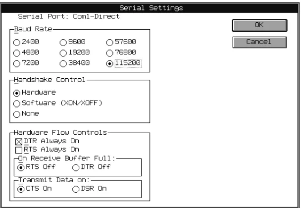
Configuring Serial Settings
The Serial Settings dialog box allows the user to set the baud rate, handshake control, hardware flow control, and transmission data settings of the serial port, for both direct and modem connections. Figure 1-6 shows the Serial Settings dialog box.
This dialog box is invoked by:
1 Clicking on the Setup command button in the Connections dialog box.
2 Clicking on the Properties command button in the Connection Setup dialog box.
3 Clicking on the Settings command button in the Connection Properties
dialog box.
En
gli
s
h
Table 1-6 describes the fields in the Serial Settings dialog box.
Table 1-6 Serial Settings Dialog Box Functions
Setting Description
Baud Rate The Baud Rate group displays the baud rates available to the user. Choose from:
2400, 4800, 7200, 9600, 19200, 38400, 57600, 76800, or 115200
The best performance is obtained by using 115200 bps, if your server supports that rate.
Handshake Control This group lets you select the Handshake Control parameters for the serial port.
Hardware handshaking ensures an orderly transmission of data between the terminal and server, through hardware flow control.
Software handshaking ensures that transmissions remain constant, via specific software communications protocols. Choose from:
Hardware (RTS/CTS) Software (XON/XOFF) None
Hardware Flow Controls The Hardware Flow Controls group lets the user select the type of hardware flow control used during terminal-to-server communications.
DTR Always On Defines the state of the DTR control signal.
Click on the DTR Always On command button to select DTR Always On. Leave the box blank to turn DTR control off. The default is DTR Always On. This setting is used with modems.
RTS Always On Defines the state of the RTS control signal.
Click on the RTS Always On command button to select RTS Always On. Leave the box blank to turn RTS control off. The default is RTS Always Off. This setting is used with modems.
On Receive Buffer Full Specifies when the Hardware Flow Control signal will turn off.
The default is RTS Off. If RTS Off is selected, the RTS Always On option will have no effect on hardware flow control. If DTR Off is selected, the
DTR Always On option will have no effect on hardware flow control.
Transmit Data on Specifies the type of modem signal that will be used by the applications server.
CTS and DSR control when the terminal is allowed to transmit data. Choose from:
CTS On DSR On
OK Click on the OK command button to accept your selections.
Cancel Click on the Cancel command button to cancel your selections. Table 1-6 Serial Settings Dialog Box Functions, Continued
En
gli
s
h
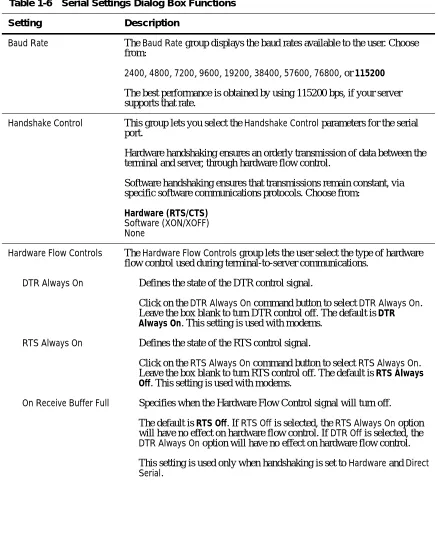
Configuring Serial Ports with Modems
The Modem group seen in the Serial Settings dialog box is used to enter the phone number of the server. Figure 1-7 shows the Serial Settings dialog box with the addition of the Modem group box.
The group also allows the user to select a modem type, enable the modem’s hardware flow control, set the modem’s speaker option, and define the modem’s initialization string.
This dialog box is invoked by:
1 Clicking on the Setup command button in the Connections dialog box.
2 Clicking on the Properties command button in the Connection Setup dialog box.
3 Clicking on either the Com1 w/modem or Com2 w/modem command buttons in the Connection Properties dialog box.
4 Clicking on the Settings command button in the Connection Properties
dialog box.
Table 1-7 describes each setting for serial modem connections.
Table 1-7 Modem Parameters
Parameter Description
Phone Number In this data field, enter the phone number of an applications server.
If a phone number is not entered, the terminal will prompt you for one. You might have to enter a prefix if you are attempting to connect to an
applications server outside your building or area code.
Modem Type Select the type of external modem that you are using from the list in the
Modem Type selection menu.
If your modem is not listed, use the User Defined option to define your modem. If you select user defined, the HW Flow Control and Speaker On
functions will be ignored. Each modem type in the Modem Type list box has a preconfigured initialization string (see Appendix B, “Modem Initilization Strings”), that initializes the modem before it dials out. New modem types can be added to this list box by entering the new modem’s initialization string in the User-Defined Init String field.
HW Flow Control Check this box to enable the modem’s hardware flow control.
Leave HW Flow Control unchecked to disable this feature. The HW Flow Control feature only works when using a modem to communicate with an applications server.
Speaker On Check this box to enable the modem’s speaker.
User-Defined Init String User-Defined Init String allows the user to enter new modem initialization strings into the modem strings initialization list.
The maximum character length for a modem initialization string is 80 characters.
En
gli
s
h
Scripting Figure 1-8 show the Security/Scripts dialog box. This dialog box is invoked by:
1 Clicking on the Setup command button in the Connections dialog box.
2 Clicking on the Properties command button in the Connection Setup dialog box.
3 Clicking on the Scripts command button in the Connection Properties
dialog box.
Figure 1-8 Security/Scripts Dialog Box
Script capability has been included to automate the login process when connecting to terminal servers or internet access servers. The scripting process listens for specific strings coming from the host connection, and when found, sends a string back to the host. This two-way dialog can be created within the
String field by entering the <exp> and <snd> text on a line-by-line basis. To facilitate script entry, special script controls can be entered into the string:
◆ <cr> is replaced with a carriage return character
◆ <lf> is replaced with a line feed character
◆ <un> is replaced with the content of the Security dialog box Username
field
◆ <pw> is replaced with the content of the Security dialog box Password
field
To create a script, first determine the login sequence used by your host or server. This can be done by asking your administrator for a description of the login sequence. Or you can use Terminal Login, going through the Terminal Login process once to learn the server’s login sequence.
❖
Note The maximum character length for each line of script is 78 characters. The maximum number of lines per script is 8.To enter a special script control such as <cr>, type <, c, r, >. Do not use spaces between characters. Lines are added to a script by:
1 Selecting <snd> or <exp>.
2 Clicking in the String field.
3 Entering the appropriate string.
4 Clicking on Add to add the string to the script.
5 Repeating steps 1 through 4 for each <snd> or <exp> string definition.
❖
Note Each script dialog is unique to one connection.Click on the OK command button when the script is completed. The Security
dialog box will close, and the script will be saved.
Table 1-8 describes a sample script.
Table 1-8 Sample Script
String Definition
<snd><cr> Send a carriage return.
<exp>Login: Expect Login:.
<snd><un><cr> Send the contents of the Username field, followed by a carriage return character.
<exp>Password: Expect Password:.
En
gli
s
h
Copying a
Connection Definition
The Copy command button from the Connection Setup dialog box (see Figure 1-4) lets the user create new connection definitions from preexisting ones listed in the Connections list. Figure 1-9 shows the Copy Connections dialog box.
To copy and create a new definition, follow these instructions:
1 Select a connection definition.
2 Click on Copy.
3 Enter the name of the new definition in the To field.
4 Click OK to accept the new connection definition.
Deleting a Connection Definition
The Delete command button from the Connection Setup dialog box lets the user delete a connection definition from the Connections list. Figure 1-10 shows the Delete dialog box.
To delete a definition, follow these instructions:
1 Select a connection definition from the Connection Setup dialog box.
2 Click on the Delete command button.
3 Click OK to delete the definition.
Figure 1-10 Delete Dialog Box
Autologin and Autoconnect
The Autologin function is located in the Connection Setup dialog box, shown in Figure 1-4. Click on the Autologin Enable check box to enable this function.
The Autoconnect function is located in the Add User Account dialog box, shown in Figure 2-2. Click on the Autoconnect Enable check box to enable this function.
Autologin
Autologin allows the user to turn on the terminal and establish a predefined connection, without entering any names, passwords, or configuration settings. Autologin, once enabled, will occur:
◆ After the terminal is turned on.
◆ After the user logs off of a connection.
En
gli
s
h
The Alt + F4 key combination is used to break out of autologin. This feature allows the user to make modifications to pre-defined connections, if the user has such privileges. The Welcome dialog box appears after the break out (see Figure 1-2), allowing the user to log back into terminal.
Autoconnect
Autoconnect allows the user to establish a connection directly from the
Welcome dialog box. The user enters a username and password in the
Username and Password data fields. The terminal then establishes a connection using the connection information in the Autoconnect function.
In most cases, the Autoconnect feature works with the Security feature. If Autologin and Security are disabled, the Autoconnect feature will not function. The exception is when the administrator uses Autoconnect, and the Autologin and Security features are disabled. Then, a predefined connection will be made. When the administrator logs off, the terminal will return to the
Connections dialog box.
When the administrator has the Autoconnect and the Enable User Password Change features enabled during a connection, the terminal will display a time-out dialog box (see Figure 2-5) while making a connection. If the user cancels the connection, the terminal will go to the Options dialog box. Once the user leaves the Options dialog box, the previous connection will resume. When the administrator has the Enable User Password feature disabled during a connection, the terminal will go directly to the server connection, and no time-out dialog box will appear.
Options Dialog
Box
The Options dialog box (see Figure 1-3) allows the user to select terminal, printer, security, and display settings. All selections are saved by clicking on the OK command button.
If the terminal’s security feature is enabled, access to all terminal, printer, and security options is denied to accounts of type user. The Options command button will be disabled. If Change Password Enabled is not selected when the account is set up, administrator accounts will have access to all options. The default for the Options dialog box is Terminal.
Terminal Properties Sheet
Terminal lets the user designate a terminal name that will be used by the server. Figure 1-11 shows the Options dialog box. This dialog box allows the user to set the power-saver and keyboard language features, and enable Verbose Connection.
The Options dialog box is invoked by clicking on the Options command button in the Connections dialog box (Figure 1-1).
En
gli
s
h
Table 1-9 describes the fields on the Terminal Properties Sheet.
Table 1-9 Terminal Properties Sheet Functions
Parameter Description
Terminal Name Use this data field to enter the name of the terminal.
The server recognizes each connected terminal by the specific name designated in the Terminal Name field. The name is unique to each terminal on the network. The terminal name also provides a useful means for locating printer and administrator functions shared on the network.
Power Saver The power-saver feature lets the user determine the duration (in minutes) that the display will be active while the terminal is left unattended.
Choose from:
Off, 5 min., 10 min., 15 min., 30 min., or 60 min.
Keyboard Language This option allows the user to select the keyboard language to use with the terminal.
Use the up-down arrow keys to scroll through the Keyboard Language
selection menu to find the desired language. US is the default.
Verbose Connection Click on the Verbose Connection checkbox to enable this function.
With Verbose Connection enabled, the terminal can report detailed error and connection messages. The Verbose Connection function is intended for users who have optional networking features installed in their terminal, and are troubleshooting a problem.
OK Click on the OK command button to accept your selections.
Printer/Aux Properties Sheet
This terminal supports local printing. To print, you will need to connect your terminal to a printer via the parallel port, or one of the serial ports. Consult your printer’s user’s guide for details.
Printer options are configured in the Printer Port group box on the Printer/Aux
properties sheet (see Figure 1-12) in the Options dialog box. The Printer Port
group box lets the user configure any of the terminal’s communications ports for local client printing. Each port can be enabled and configured individually. Multiple ports can be configured as printer ports. Serial ports can be used for printing, and can also be used for peripheral devices such as scanners or bar code readers.
Invoke the Printer/Aux properties sheet by:
1 Clicking on the Options command button in the Connections dialog box.
2 Clicking on the tab on the Printer/Aux properties sheet.
En
gli
s
h
Table 1-10 describes the Printer/Aux option parameters.
❖
Note The server must be configured to use the local serial or parallel ports, through the server net use commands. Consult your server’s administrator guide for more details.Table 1-10 Printer/Aux Properties Sheet Functions
Option Description
Printer Port This group box allows the user to enable any port (or multiple ports) listed as a printer port.
Parallel Port Click on this check box to enable the terminal’s parallel port for local printing.
The default is enabled.
Com1 Serial Port Click on this check box to enable the terminal’s COM1 port for local printing.
The default is enabled.
Com2 Serial Port Click on this check box to enable the terminal’s COM2 port for local printing.
The default is enabled.
OK Click on this command button to accept your settings and return to the
Connections dialog box.
Cancel Click on this command button to cancel your settings and return to the
Connections dialog box.
Com1 Settings Click on this command button to invoke the Com1 Serial Printer Settings
dialog box (see Figure 1-13).
Serial Printer Settings Dialog Box
The Com Settings command buttons on the Printer/Aux properties sheet lets you configure Com1 or Com2 for printing. Figure 1-13 shows the Com1 Serial Printer Settings dialog box.
❖
Note The Com2 Serial Printer Settings dialog box is the same as Figure 1-13.Invoke the Com1 Serial Printer Settings dialog box by:
1 Clicking on the Options command button in the Connections dialog box.
2 Clicking on the Printer/Aux tab on the Printer properties sheet.
3 Clicking on the Com1 Settings command button.
❖
Note The Com2 Serial Printer Settings dialog box can be invoked by clicking on the Com2 Settings command button in Step 3 above.Figure 1-13 Com1 Serial Printer Settings Dialog Box
En
gli
s
h
Table 1-11 describes each setting.
Table 1-11 Serial Printer Settings Dialog Box Functions
Setting Description
Baud Rate Baud Rate sets the printer’s baud rate.
Choose one of the following:
300, 600, 1200, 2400, 3600, 4800, 7200, 9600, 14400, 19200, 28800, 38400,
57600, 76800, or 115200
Handshake Control The Handshake Control group box allows the user to select the handshake control setting for a serial port.
Handshaking ensures an orderly transmission of data through hardware flow control, between the terminal and the applications server.
Software handshaking ensures that transmissions remain constant via specific software communications protocol.
Choose from:
Hardware (RTS/CTS) Software (XON/XOFF) None
Data Bits Sets the port’s data bit to match the printer’s requirements.
Choose from:
8-bits or 7-bits
Stop Bits Set the port’s stop bit to match the printer’s requirements.
Choose from:
1-bit or 2-bits
Parity Set the port’s parity to match the printer’s requirements.
Choose from:
None, Mark, Space, Even, or Odd
OK Click on the OK command button to accept the settings, and exit the dialog box.
Aux Handshake Modes
Either of the two basic handshaking modes (hardware or software) can be used to control the flow of data through the Aux (Auxiliary) port. Which mode is selected depends upon how the connected host uses the port, and how the active host application addresses the port.
When the Aux port is used as a serial printer port, the hardware handshaking mode uses the DTR/DSR (Data Terminal Ready/Data Set Ready) signals to control the flow of data through the port.
When the Aux port is used as a bidirectional communication port, the hardware handshaking mode uses the RTS/CTS (Request To Send/Clear To Send) signals to control the flow of data through the port.
If the software handshaking mode is selected, the Aux port uses the XON/ XOFF handshake signals to control data flow.
The settings in the Aux Handshake Modes table are configured in the COM1
and COM2 Settings dialog boxes.
❖
Note When the terminal is logged into the server via COM1 or COM2, and the port is enabled as a printer port, the printer configuration will be ignored by the server. The server will not recognize it as a local printer port, but as a server connection. Local serial port settings do not affect a server-connected serial port’s setting.Table 1-12, Aux Handshake Modes, describes the available modes for both the printer and the Aux functions.
Table 1-12 Aux Handshake Modes
Handshake Type
Handshake
Modes Printer Port Aux Port
Hardware DTR/DSR ✓
Hardware RTS/CTS ✓
En
gli
s
h
Display Properties
Sheet
The terminal’s screen display options are adjusted in the Display properties sheet. Figure 1-14 shows the Display properties sheet.
This properties sheet is invoked by:
1 Clicking on the Options command button in the Connections dialog box.
2 Clicking on the Display tab in the Options dialog box.
Figure 1-14 Display Properties Sheet
The Display properties sheet is described in Table 1-13.
❖
Note The connection resolution and color selection will vary by products. Table 1-13 Display Properties Sheet FunctionsFields Description
Color This group box allows you to select the maximum number of colors supported on the terminal screen.
Connection Resolution
This group box allows you to select the maximum resolution of the display.
OK Click on OK to accept your modifications
En
gli
s
h
2
Administrator and
User Functions
The terminal security features gives administrators the means to restrict access to sensitive terminal functions. These features allow the user to automatically log onto (Autologin), and/or automatically connect (Autoconnect) to a server, based on user account information.
❖
Note These functions relate to the terminal only. They should not be confused with network or server functions.The AutoConnect feature is disabled at the factory, leaving the terminal accessible to modification of the terminal settings and illegal log on. Enabling the security feature, and setting up administrator and user-privileged accounts protects the terminal and the network against unwanted access. This chapter explains how to enable these features.
❖
Note Terminal security configurations have no effect on Windows NT applications servers.Administrator and
Terminal User
Accounts
Terminal security allows two types of accounts— administrator and user:
◆ Administrator accounts provide full access to all user accounts, connection definitions, passwords, and terminal settings and features.
◆ User accounts only provide access to user account passwords. User accounts are restricted from administrator privileges.
The terminal is equipped with a predefined administrator account called Administrator. You can change this account’s properties, such as its password, domain, and auto-connection function. However, the Administrator account cannot be deleted from the terminal.
Security
Properties Sheet
Security is enabled in the Security properties sheet. Figure 2-1 shows the
Security properties sheet.
This feature is enabled by:
1 Clicking on the Options command button in the Connections dialog box (see Figure 1-1).
2 Clicking on the Security tab in the Options dialog box.
3 Clicking on the Security Enable check box to enable security.
Figure 2-1 Security Properties Sheet
Once the security feature is enabled and the terminal is reset, a terminal logon name and password is required to regain access to the terminal. Logon is done in the Welcome dialog box, which displays once the terminal is turned back on (see Figure 1-2, Chapter 1).
If you entered a user name that does not have administrator privileges, the
En
gli
s
h
Adding Terminal User Accounts
The Add User Account dialog box adds user accounts to the terminal.
This dialog box is invoked by:
1 Clicking on the Options command button in the Connections dialog box (see Figure 1-1).
2 Clicking on the Security tab in the Options dialog box.
3 Clicking on the Add User command button.
Figure 2-2 shows the Add User Account dialog box.
Figure 2-2 Add User Account Dialog Box
When you are finished adding a user account, click OK to accept the new account. Click on Cancel at any time to quit the dialog box.
Table 2-1 describes each field in the Add User Account dialog box.
Table 2-1 Add User Account Field Descriptions
Field Description
UserName Enter the terminal user account name in this field.
Password Enter the terminal user account password in this field.
Confirm Password Enter the password again in this field.
This confirms and validates the password you entered in the Password field. If a confirmation is not made, an error message box will appear. The error message box prompts you to reenter the password.
Administrator Privilege Enable
Check this box if you want to assign administrator privileges to a terminal user account.
You must select this function or Enable User Password Change if you want the Options dialog box available.
Accounts with administrator privileges are identified as Admin in the
Privilege column of the Terminal Username list. Selecting this function disables Enable User Password Change.
The default is disabled.
Enable User Password Change
Check this box to allow the user to make changes to the password.
You must select this function or Administrator Privilege Enable if you want the Options dialog box available.
If the Enable User Password Change feature is enabled, then the
Administrator Privilege Enable is disabled.The two functions are mutually exclusive. If both functions are disabled, then the Option command button in the Connections dialog box will not be available, and there will be no connect time-out during auto-connect.
The default is enabled.
AutoConnect Enabled When enabled, this feature automatically connects the terminal user account to a defined connection during login.
AutoConnect can be independently enabled and associated with any connection definition. See “Auto-Connections” in this chapter, for more details.
The default is disabled.
En
gli
s
h
Modifying Terminal User Accounts
Terminal user account modifications are made by selecting an account from the Terminal Username list in the Security properties sheet of the Options
dialog box (See Figure 2-1). Next, click on the Modify User command button to invoke the Modify User Account dialog box (Figure 2-3). The account you selected appears in the Username field. This dialog box is similar to the Add User Account dialog box, with exceptions listed in Table 2-2.
Table 2-2 describes each field in the Modify User Account dialog box.
Table 2-2 Modify User Account Fields
Field Description
Username The Username field displays the terminal user name, and cannot be changed.
New Password Enter a new password in this field.
Enter it again in the Confirm Password field, to confirm and encrypt the new password.
Administrator Privilege Enable
Click on this box if you want to assign administrator privileges to a terminal user account.
Accounts with administrator privileges are identified as Admin in the
Privilege column of the Terminal Username list. This list is in the Security
properties sheet of the Options dialog box.
Enable User Password Change
Check this box to allow the user to make changes to the password.
If the Enable User Password Changes feature is enabled, then the
Administrator Privilege Enable is disabled.The two functions are mutually exclusive. If both functions are disabled, then the Option command button in the Connections dialog box will not be available, and there will be no connect time-out during auto-connect.
AutoConnect Enabled When enabled, this feature automatically connects the terminal user account to a defined connection.
Autoconnect can be independently enabled, and associated with any connection definition. See “Auto-Connections” in this chapter, for more details.
AutoConnect to Select a connection definition that will be associated with the current terminal user account.
The auto connect feature must be enabled. See “Auto-Connections” in this chapter, for more details.
OK Click on OK to accept your modifications
En
gli
s
h
Deleting Terminal User Accounts
The Delete command button from the Security properties sheet allows the user to delete a user name from the Terminal Username list. Figure 2-4 shows the
Delete dialog box.
To delete a user, follow these instructions:
1 Select a name from the Terminal Username list in the Security properties sheet of the Options dialog box.
2 Click on Delete.
3 Click OK to delete the user name.
❖
Note The predefined administrator account can never be deleted. If this is attempted, an error message will appear.Auto-Connections
The Auto-Connect feature automatically connects the terminal to a Windows NT applications server, if that terminal account has the Auto-Connect feature enabled. Figure 2-5 shows the Auto-Connect (time-out message) Message dialog box. This feature is enabled from the Add User andModify User Account dialog boxes.
When an account has Auto-Connect enabled, and a connection is attempted, the Connection dialog box will not display. Instead, a time-out message, the Autoconnect message dialog box will appear.
Figure 2-5 Autoconnect Message Dialog Box
If Enable User Password Change is not enabled, the password dialog box will not show and the time-out message will not appear.
When a connection is made, you will see the Windows NT login screen,
Program Manager, or your application (if you entered a command line and working directory in the Connection Properties dialog box).
If security is enabled and a password is in a user account, and you abort a connection, a terminal user Options dialog box (Figure 2-6) will appear. This dialog box allows the user to change passwords.
If security is disabled, and you want to abort the connection process, press any key on the keyboard. Pressing any key will bring you back to the Connections
En
gli
s
h
Figure 2-6 Options Dialog Box
The Options dialog box’s fields are described in Table 2-3.
Table 2-3 Options Dialog Box Fields
Fields Description
Terminal Password This group box allows the user to recreate and confirm the terminal password.
UserName Identifies the current terminal user name. This name cannot be changed.
New Password Enter a new user password in this field.
Confirm Password Enter the user password again to confirm the password.
Host Connection Password This group box allows the host logon user to change and confirm the Windows NT applications server password.
UserName Identifies the current Windows NT application server user’s name. This name cannot be changed.
New Password Enter the application server user’s new password in this field.
En
gli
s
h
A
Serial and Parallel Port
Pin Assignments
Figure A-1 Serial Pin Assignments
Figure A-2 Parallel Pin Assignments
En
gli
s
h
B
Modem Initialization Strings
Initialization strings sent from the modem depend on the type of modem selected from the Serial Settings dialog box (see Chapter 2, “Administrator and User Functions”). Initialization strings for the terminals predefined modem types are shown in Table B-1.
Table B-1 Modem Initialization Strings Defaults
Modem Initialization String
H/W Flow
Control Speaker
Cardinal MVP288XF
AT&F&C1&D2 V1 X4 S0=0 S7=55 W0 S95=44 AT&Q5 S46=138<hardwareflowcontrol><speaker> Off: &K0 On: &K3 Off: M0 On: M1 Hayes Accura 28800
AT&F&C1&D2 V1 X4 S0=0 S7=55 W0 S95=44 AT&Q5<hardwareflowcontrol><speaker> Off: &K0 On: &K3 Off: M0 On: M1 Practical Peripherals PM288MT
AT&F&C1&D2 V1 W1 S0=0 S7=55 S95=44 AT&Q5 S46=2<hardwareflowcontrol><speaker> Off: &K0 On: &K3 Off: M0 On: M1 UDS Motorola PowerClass 28.8 AT&F
AT &C1&D2 \V1 S0=0 S7=30
AT\N7%C1<hardwareflowcontrol><speaker> Off:\Q0 On:\Q3 Off: M0 On: M1 US Robotics Sportster VFC 28.8
A <cr> (carriage return) character is automatically sent at the end of each AT command string.
Control characters can be embedded into the modem initialization strings. The syntax is <control character>. For example, <0a> (<zero a>) can be inserted in a string to force a line feed.
En
gli
s
h
C
Troubleshooting
This troubleshooting guide provides solutions to problems that may occur when making a terminal network connection to a Windows NT applications server. If you cannot resolve an issue, call an authorized service center for assistance.
Problem Solution
When the terminal is turned on, nothing happens. Check the power cord. It should be plugged into an AC outlet, and pushed all the way into the AC power connector on the terminal’s back panel.
When the terminal is turned on, the screen remains black. The power-on indicator light is orange.
Set the terminal to factory defaults. Factory defaults can be obtained by turning the terminal off then on, while holding down the G key. When you see the Connection dialog box, release the G key. The terminal’s factory defaults are now restored.
When the terminal is turned on, the Connection or
Welcome dialog box appears, but the mouse does not function.
Ensure that the mouse is plugged into the PS/2 mouse port on the terminal’s back panel. See the installation guide for the location of the PS/2 connector.
During the terminal’s Power-On Self-Test, a message is displayed:
The terminal cannot detect a keyboard. The keyboard is bad, missing, or not connected properly.
Ensure that a PS/2 keyboard with a PS/2 or RJ-9 cable is connected to the keyboard connector on the terminal’s back panel.
When you are entering a login name and password, a message window displays:
Invalid Terminal User Account information.
The terminal has built-in security that is
independent of the applications server login name and password. That security function is telling the user that the name and password entered has either expired, or is wrong. Enter the name and password again. If the same message appears, ask the administrator for a new terminal login name and password.
When you are attempting to connect to an applications server, the screen goes blank. The terminal screen either freezes, or an error message is displayed:
Error 1034 (0x40a) - I/O Error.
1 Check the host port connection. It should be configured for a WinStation connection. If it is not, configure the host port for a WinStation connection using the WinStation Configuration
utility in the Administrative Tools group box.
2 Check the WinStation port to see if it is enabled. If it is not, enable the WinStation port from the WinStation Configuration utility in the
Administrative Tools group. Start the
WinStation Configuration utility, highlight the port you want to enable, pull-down the WinStation pull-down menu, and select Enable.
3 Check the terminal’s and the server’s communication ports. Both ports should be configured identically. To compare port settings, start the WinStation Configuration
utility, highlight the port you want to look at, and double click on it. Next, click on the
Advanced button. See Chapter 1 for information about the terminal’s communications settings.
4 Check all cabling between the terminal and the server. The cables should be secure, and connected to the correct ports on both the terminal and the applications server. See Appendix A for serial communication pin assignments. Pin assignments must be compatible with those on the applications server’s serial port.
5 If the user is using XON/XOFF handshaking, check your WinStation port to see if it is using the appropriate XON/XOFF characters. To check these settings, start the WinStation
Configuration utility. Highlight the port you want to examine, and double click on it. Next, click on the Advanced button. The characters should be Xon, character 0x11 (Hex) and Xoff, character 0x13 (Hex).
6 A connection was attempted while the server was either in shutdown, or crashing. See your ICA 3.x-compatible server documentation for instruction about restarting the applications server.
7 Refer to your ICA 3-compatible server documentation for details.
En
gli
s
h
With a serial connection already established, the mouse cursor moves, but the keyboard input and mouse clicks do not work, and all the applications are frozen.
1 The serial connection to the server is broken. Turn off, then turn on the terminal. Log back into the applications server. If the computer sustained a disconnect time-out, the original desktop prior to the disconnect will be re-established (if the connection was defined to do so). See your ICA 3.x server documentation to find out how to change the disconnect time.
2 If the terminal cannot log back in, verify that all cables between the terminal and the applications server are connected. Check any modem connections between the terminal and server are not open. Ensure that the
applications server’s port that your WinStation session is connected to is not down. See your ICA 3.x server documentation for more information.
3 Make sure you are using a shielded cable that meets RS-232 standards, and that you are operating within RS-232 standards.
The parallel printer connected to my terminal does not respond when I try to print to it.
1 Make sure that printer is plugged in to the proper outlet, and that the printer is turned on.
2 Check the cable connection to the printer and to the terminal.
3 Make sure that the printer is online.
4 Make sure that Parallel Port box in the terminal’s Options/Printer/Aux dialog box is enabled.
5 Make sure that the printer is properly configured in the application server’s Print Manager, and that the printer has not been paused. See your ICA 3-compatible server documentation for instruction about using the Print Manager.
6 See Appendix A for parallel communications pin assignments.
❖
Note If any other error messages are displayed, or you have any other problems, you should default the terminal and reconfigure it. Factory defaults can be restored by turning the terminal off then on, while holding down the Gkey. Release the G key when the Connections dialog box appears. The terminal’s defaults will be restored, and you can then reconfigure the terminal. The serial printer connected to the terminal will not
print.
1 Ensure that the power to the printer is turned on.
2 Check the cable from the terminal to the printer for proper connection.
3 Ensure that the printer is online.
4 Check the Com port selection in the Printer/Aux Printer Port group box in the Options dialog box. Ensure that the printer cable is connected to the corresponding serial port on the terminal’s back panel.
5 Ensure that both the terminal’s and the printer’s serial ports are identically configured. Both must use the same handshaking protocol. To compare these settings, see Chapter 2. See the printer’s user’s guide for information about printing from a serial connection.
6 Ensure that the printer is configured properly in the applications server’s Print Manager, and that the printer has not been paused. See your ICA 3.x server documentation for instructions about using the Print Manager.
7 Refer to Appendix A for serial communications pin assignments. Pin assignments must be compatible with those on your printer’s serial port.