Path search algorithms for
application in W-CDMA systems
M.Sc. Thesis
Marijn C. Damstra
University of Twente
Department of Electrical Engineering,
Mathematics & Computer Science (EEMCS) Signals & Systems Group (SAS)
P.O. Box 217 7500 AE Enschede The Netherlands
Report Number: SAS020-04 Report Date: August 16, 2004
Period of Work: 01/10/2003 – 16/08/2004 Thesis Committee: Prof. Dr. ir. C.H. Slump
Abstract
The CADTES and SAS groups of the EEMCS faculty are working on the Adaptive Wireless Networking (AWGN) project. As part of this project adaptive algorithms are developed for digital signal processing in W-CDMA systems. One of these algorithms is the path search algorithm that estimates the delays of the paths between a transmitter and a receiver that are caused by reflections. Several options exist for implementing the path search algo-rithm. One of the questions posed within the AWGN project is: to what extent will it be useful for the path search function to switch between differ-ent algorithms, as the conditions between transmitter and receiver change?
First, this document presents an overview of path search algorithms from literature. About twenty papers are discussed, the algorithms they describe have been compared with each other on sixteen points. Based on the sim-ilarities that are discovered, the algorithms are classified in three classes: algorithms using a Power Delay Profile (PDP), algorithms based on a Maxi-mum Likelihood Estimation (MLE) method and subspace-based algorithms.
Next, an algorithm is selected from each class. Both the Power Delay Profile and the Maximum Likelihood algorithms are implemented, the sub-space algorithm is analyzed in theory only. In order to set up meaningful simulations channel models and simulation scenarios are investigated. The available simulator is discussed, as well as the modifications that were made.
The algorithms’ performance is determined by simulation, results show that the MLE algorithm outperforms the PDP algorithm in most situa-tions. The MLE algorithm however requires more computations under all circumstances. In view of this trade-off between performance and number of computations the MLE algorithm should be used in case of closely spaced paths, if time-variant path delays need to be estimated and if strong Doppler effects occur. BER simulations will have to be carried out to quantify the benefits of selecting the MLE algorithm in these cases.
Acknowledgments
For my M.Sc. thesis I was looking for an assignment in the area of algorithm development for wireless digital communications systems. Having discussed the options with professor Slump, I decided to visit ir. Potman to hear more about his Ph.D. dissertation as part of the Adaptive Wireless Network project. Inspired by his enthusiasm I opted for studying Path search
algo-rithms for application in W-CDMA systems.
During the first part of my M.Sc. thesis I have spent quite some time rereading a number of books from previous courses on wireless communi-cations, CDMA systems, digital signal processing, channel models, radio propagation etcetera. Having finished the literature study, I started work-ing on the implementation of the path search algorithms, followed by the simulations. I enjoyed working on this part and I appreciate the inspiring discussions and enthusiasm of both ir. Potman and ir. Hoeksema during our fruitful bi-weekly meetings.
At the end of my thesis’ work I would very much like to thank professor Slump, ir. Potman and ir. Hoeksema for their support.
Enschede, August 16th 2004 Marijn Damstra
Contents
Abstract i
Acknowledgments iii
Table of Contents vii
1 Introduction 1
2 Literature study 3
2.1 Overview of the literature study . . . 3
2.2 Selection of papers for the literature study . . . 4
2.3 Received signal model . . . 4
2.4 Characteristics of path search algorithms . . . 6
2.5 Discussion of the papers . . . 7
2.5.1 Power delay profile-based path searchers . . . 7
2.5.2 Maximum Likelihood-based path searchers . . . 15
2.5.3 Subspace-based path searchers . . . 21
2.6 Selection of three algorithms . . . 28
3 Simulation environment for path search algorithms 29 3.1 Multipath channel models . . . 29
3.1.1 Jakes’ channel model . . . 30
3.1.2 L-path channel model . . . 30
3.1.3 3GPP and ITU-R Vehicular B channel models . . . . 31
3.1.4 Measurements of channel impulse responses . . . 32
3.2 Scenarios for simulations . . . 32
3.2.1 Outdoor rural area . . . 32
3.2.2 Outdoor urban area . . . 33
3.2.3 Indoor office area . . . 33
3.2.4 Propagation conditions . . . 34
3.2.5 Modifications to the simulator . . . 34
vi Contents
4 A Power Delay Profile-based path searcher 37
4.1 Introduction . . . 37
4.2 Setting up interfaces and structuring the algorithm . . . 38
4.3 Discussion of the PDP algorithm in detail . . . 38
4.3.1 Estimating the delay profile using correlation . . . 38
4.3.2 Calculating the Power Delay Profile . . . 39
4.3.3 Detection of local maxima in the PDP . . . 39
4.3.4 Setting a threshold for the PDP . . . 40
4.3.5 Selecting the paths from the PDP . . . 40
4.4 Simulation of the PDP path searcher . . . 40
5 A Maximum Likelihood Estimation algorithm 41 5.1 Introduction . . . 41
5.2 Model of the baseband received signal . . . 42
5.3 Principle of Maximum Likelihood Estimation . . . 43
5.4 Principle of Expectation Maximization . . . 43
5.5 Discussion of the MLE-EM algorithm in detail . . . 44
5.5.1 Expectation: Forming the shifted scrambling codes . . 45
5.5.2 Expectation: Determining the path signal estimates . 46 5.5.3 Maximization: Correlating the path signal estimates with the scrambling code . . . 46
5.5.4 Maximization: Estimating the path parameters . . . . 46
5.5.5 Determining the convergence rate of the parameter estimates . . . 47
5.6 Simulation of the MLE-EM path searcher . . . 47
6 Performance of the PDP and MLE algorithms 49 6.1 Goal of the simulations . . . 49
6.2 Performance of the algorithms in Rayleigh fading channels . . 51
6.2.1 Vehicular B channel model . . . 51
6.2.2 Pedestrian B channel model . . . 53
6.2.3 Case 3 channel model . . . 55
6.2.4 Office B channel model . . . 57
6.3 Doppler effects . . . 59
6.4 Influence of the algorithms’ parameters on their performance 60 6.4.1 Parameters of the PDP algorithm . . . 60
6.4.2 Parameters of the MLE algorithm . . . 61
6.5 Resolution of the algorithms: resolving closely spaced paths . 64 6.6 Acquiring and tracking . . . 65
6.7 Extension of the simulator . . . 66
6.7.1 Handover to a second basestation . . . 66
6.7.2 Moving propagation conditions . . . 67
6.7.3 Birth-death propagation conditions . . . 68
CONTENTS vii 7 Conclusions and future work 71
7.1 Summary of work . . . 71
7.2 Comparison of the PDP and MLE algorithms . . . 72
7.3 Switching conditions . . . 74
7.4 Recommendations . . . 75
A List of acronyms 77 B A Subspace-based path searcher 81 B.1 Introduction . . . 81
B.2 Model of the baseband received signal . . . 82
B.3 Principle of Subspace-based path searcher . . . 83
C A Power Delay Profile-based path searcher in C++ 85 C.1 path searcher TOP h . . . 85
C.2 downlink receiver h . . . 87
C.3 downlink receiver cpp . . . 90
C.4 pdp path searcher h . . . 95
C.5 pdp path searcher cpp . . . 97
D A MLE-EM path searcher in C++ 101 D.1 mle path searcher h . . . 101
D.2 mle path searcher cpp . . . 103
1
Introduction
Currently the CADTES group and the SAS group of the EEMCS faculty are working on the Adaptive Wireless Networking (AWGN) project that is sponsored by Freeband. The goal of the AWGN project is the development of adaptive algorithms for digital signal processing and the mapping of these algorithms on a flexible hardware architecture. Within the AWGN project mostly adaptive algorithms are investigated that can be applied in CDMA systems, such as UMTS.
One of these algorithms is the so-called path search algorithm. It is used to estimate the delays of the different paths between a transmitter and a receiver that are caused by reflections. Several options are available for im-plementing the path-search algorithm. One of the questions posed within the AWGN project is: to what extent will it be useful for a certain function to switch between different algorithms, as the conditions between transmit-ter and receiver change?
As part of the AWGN project, the goal of this M.Sc. thesis is to answer this question for the path search algorithm. In order to provide an answer, existing path search algorithms have been researched in literature. The pos-sible implementations of the path search algorithm have been investigated and are presented in this document (Chapter 2). If possible the circum-stances under which these algorithms show the best performance are noted, as well as a measure for their performance.
Before implementing the algorithms and setting up simulations first a number of channel models are analyzed in Chapter 3. Also scenarios have been formulated in Chapter 3 that describe the conditions in the channel between the transmitting base station and the receiving mobile terminal.
2 Introduction
1
2
Literature study
2.1
Overview of the literature study
To get a clearer picture of the different techniques for implementing the path search algorithm papers have been searched in literature about this. In Sec-tion 2.2 it is briefly discussed which sources have been used and according to which method the papers have been searched. This resulted in about twenty papers. In Section 2.3 a model of the received signal is presented, for a better understanding of the papers. The algorithms have been compared with each other on sixteen points; these points are addressed in Section 2.4.
The discussion of the algorithms that were found follows in Section 2.5. During the literature study it turned out that there are several resemblances between the algorithms that were found. Based on these resemblances it was possible to classify the algorithms in three classes.
The first class that was identified consists of algorithms that use a Power Delay Profile. This class of algorithms is described in Subsection 2.5.1, in-cluding an overview of the papers. A second group of algorithms is based on a Maximum Likelihood method, the papers are discussed in Subsection 2.5.2 in detail. Subspace-based algorithms form the last group (Subsection 2.5.3).
One of the questions of the AWGN project (Chapter 1) is: to what extent is it useful to switch between several types of algorithms that can carry out the path search function, as conditions change between transmitter and receiver? To be able to answer this question, the algorithms will be implemented during the next phase of this M.Sc. thesis. One algorithm from each of the classes is selected, as will be discussed in Section 2.6.
4 Literature study
2
2.2
Selection of papers for the literature study
In order to find papers discussing path search algorithms a table of keywords was drafted. This table contains a variety of combinations of one or more words from the following list:
path multipath channel algorithm search∗ delay estimat∗ cdma
∗ is a wildcard, ”estimat∗” can be ”estimator” or ”estimation” and so on, ”search∗” can be ”searcher” or ”searching”. Search engines provided by a number of organizations were used to find papers discussing techniques for path searching, using the generated table of keywords. They include:
database: provided by: available at:
IEEExplore IEEE http://ieeexplore.ieee.org
Universiteits Bibliotheek University of Twente http://opc4.civ.utwente.nl
Picarta OCLC PICA http://picarta.pica.nl/
Web of Science ISI http://isi4.isiknowledge.com/portal.cgi/wos
Current contents ISI University of Twente library
Compendex Elsevier Engineering Information http://www.engineeringvillage2.org/ Inspec Elsevier Engineering Information http://www.engineeringvillage2.org/
Google Google http://www.google.com/
Altavista Altavista http://www.altavista.com/
This resulted in a large number of papers, which were processed in two phases. During the first phase the most relevant papers were selected based on their abstracts. These papers were then fully processed and the most rel-evant ones have been selected for the literature study. They will be discussed in detail in Section 2.5.
2.3
Received signal model
The papers present algorithms that process the signal that is received from a multipath channel. The signal that is transmitted by user k over the multipath channel can be described asxk(t):
xk(t) =
r
εb,k
Tb P0−1
X
i=0
bk(i)sk(t−iTb) (2.1)
In (2.1) bk(i) ∈ {−1,1} is the ith symbol, transmitted with energy εb,k,
Tb is the symbol duration, P0 denotes the packet length and sk(t) is the
spreading waveform:
sk(t) = Nc−1
X
n=0
s(kn)ψ(t−nTc) (2.2)
2.3 Received signal model 5
The channel impulse response hk(t) can be described as a sum of L mul-tipaths that result in a sum of superimposed versions of the transmitted signalxk(t).
hk(t) = L
X
l=1
αk,lδ(t−τk,l)ejφk,l (2.3) In (2.3) L indicates the number of paths in the channel and αk,l and
τk,l indicate respectively their complex attenuation and delay. The received signalr(t) can be described as follows:
r(t) = K
X
k=1
hkxk(t−τk,l) +w(t) (2.4)
6 Literature study
2
2.4
Characteristics of path search algorithms
Of each paper it will be discussed in what kind of system the path search algorithm is applied and under what kind of circumstances. For this the channel model that is used will be discussed, as well as the scenario. The scenario describes the circumstances under which the algorithm is applied, for example whether the algorithm is used in a mobile terminal or in a base station, the number of multipaths that are present and whether there are other mobile terminals sending over the channel. If there are other users sending over the channel the received signal will contain signal components from these users as well, due to the non perfect orthogonality of their codes. This is called Multiple Access Interference (MAI) [34]. In the discussion of the channel model it will be indicated whether it includes Doppler ef-fects and what type of fading (see [34]) occurs (fast/slow and flat/frequency selective fading). If possible the delay spread is noted, that indicates the maximum path delay.
For each paper the set-up of the path search algorithm will then be dis-cussed. It will be indicated whether the algorithm is based on a correlator [27], a matched filter [27] or on another method. Algorithms can exploit pilot tones (pilot aided estimation) or not (blind estimation). Most of the algorithms consist of three parts. The first part estimates the parameters of the paths in the channel (delay and attenuation), the second part estimates the power of the paths that are found and the third part selects a number of these paths for demodulation by e.g. a Rake receiver [34].
Finally, the robustness and performance of each algorithm is investi-gated. The robustness of the algorithms is assessed by the extent to which the algorithm is sensitive to the near-far effect [34] and to Multiple Access Interference. The performance of the algorithms is verified by computer simulations in the majority of the papers.
2.5 Discussion of the papers 7
2.5
Discussion of the papers
2.5.1 Power delay profile-based path searchers
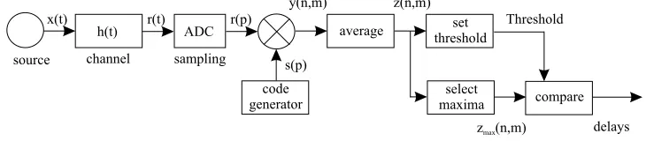
A large number of papers analyzed so-called Power Delay Profile (PDP)-based path searchers. The PDP-(PDP)-based path searcher is depicted in Figure 2.1:
h(t) average set
threshold
select
maxima compare
code generator
x(t) r(t)
s(p)
y(n,m) z(n,m)
Threshold
z (n,m)max delays
source channel
ADC r(p)
sampling
Figure 2.1: Power Delay Profile-based path searcher
Algorithms of this type search paths in three steps. During the first step the complex received baseband signalr(p) is correlated with a replica of the user signatures(p). Generally the received signal consists of a series of pilot symbols, which means that this signal contains the user signature. In this way a correlated signal y(n, m) is obtained for the nth frame, that contains a number of peaks for the different delays τi,l. These peaks correspond to the paths in the channel between transmitter and receiver.
y(n, m) = 1
N
N−1
X
p=0
hi(p)δ(m−
τi,l
Tc
) + ˜w(n, m) (2.5)
N is the correlation window size, p the discrete time index and m the correlation index. δ(m− τi,l
Tc) results from the autocorrelation of the user
signaturesi(p) of the user iand ˜w(n, m) is the correlated noise.
The next step is to find the most significant paths. For this a Power Delay Profilez(n, m) is determined based on the signal y(n, m). This PDP is a measure for the received power in each of the paths that is found (M
indicates the length of the summation).
z(n, m) = 1
M
M−1
X
k=0
|y(n−k, m)|2 (2.6)
Finally a limited number of paths from the PDP is selected. In order to do this a threshold value is set for the power of the paths. There are several methods for calculating this threshold value, for example by means of an estimate of the power of the noise. Generally speaking,η is set as:
8 Literature study
2
Estimatingσn2 is crucial for setting threshold η. Most papers base their noise variance estimate on the PDP. As it contains peaks for the detected paths, the PDP needs to be modified in order to determine the noise variance estimate. Some papers suggest to subtract the strongest paths from the PDP [13] [28] or subtract a WMSA filtered signal from the PDP [12]. In [25] the threshold is simply set to
η = 1
P
P−1
X
m=0
z(n, m)(a+bMc) (2.8)
M is the averaging length and P the correlation length.
In the next subsections the found power delay profile-based path searchers will be discussed. Because of the width of the main lobe of the autocorrela-tion most of these algorithms have a resoluautocorrela-tion of one chip period or more.
2.5.1.1. Path searcher for a WCDMA Rake receiver
In [25] an algorithm is described for finding paths that is suitable for W-CDMA systems. The channel is modelled as a filter in discrete time, no information concerning the type of fading is given. Paths are characterized in the model by their delay and attenuation and the channel has a certain delay spread (20µs). Furthermore, no Doppler effects occur. The described algorithm is used in the mobile terminal (downlink), the number of users in the cell is not mentioned and their interference is considered as white noise.
The algorithm is based on a correlator that makes use of a pilot tone in the received signal from the Primary Common Pilot Channel (P-CPICH). By calculating the correlation over the length of a frame, a Power Delay Pro-file is found. This PDP is then averaged over a number of previous frames, to suppress fast fluctuations as a result of interference (non-coherent averag-ing). Based on this average the PDP threshold is calculated. Parallel to this maxima are searched in the average PDP based on a three points method. The height of the found maxima (attenuation) is then compared with the threshold. If it exceeds the threshold then the associated delay is assigned to a finger of a Rake receiver.
2.5 Discussion of the papers 9 2.5.1.2. Path-search algorithm introducing path-management ta-bles for a DS-CDMA mobile terminal
In [13] a path search algorithm is presented for wideband direct sequence (DS) CDMA systems, that has been extended with three path management tables. The channel model shows Rayleigh fading (2 paths), and Doppler effects occur (fd = 5.6 Hz). The described algorithm is used in the mobile terminal (downlink), the number of users in the cell is not mentioned and their interference is not modelled separately.
The path searcher consists of three parts: a spreading code generator, a correlator and a power measurement block. It uses the common pilot sym-bols in the received signal. The correlator performs the correlation of the received signal with the generated spreading code and the power measure-ment block then calculates a PDP. The paper discusses the selection of the paths in detail and proposes three management tables to aid this selection. The first table contains the data of the path searcher (ten strongest paths from PDP). The table is initialized on the basis of the momentaneous PDP and is adapted by using a first order forgetting filter.
The second table resides in the Rake combiner. This table contains the data of the paths which have been assigned to the fingers of the Rake re-ceiver. For this the data from the channel estimator in the Rake receiver is used. This table is also updated using a filter with a forgetting factor. The third table is updated by multiplying the signal strength of each path in the second table by a weighing factor and adding it to the strength of the corresponding path in the first table. Finally the strength of the paths from the third table is compared to a threshold.
The performance of the presented algorithm has been examined by sim-ulating the Block Error Rate (BLER) as a function of the SNR. For com-parison the performance of a conventional path search algorithm (without management tables) and the performance of the ideal case (in which the two paths are selected) are used.
2.5.1.3. Performance analysis of multipath searcher in WCDMA system
10 Literature study
2
The algorithm is based on a correlator which uses the pilot tone in the received signal from the Dedicated Physical Control Channel (DPCCH). The correlated signal is then accumulated (coherent or non-coherent) over a number of slots. Finally a Power Delay Profile is calculated by squaring this signal. Based on this PDP the paths will be selected using a certain threshold value. Expressions are inferred for the chance of detection (Pd), miss (Pm) and false alarm (Pf).
The performance of the algorithm is examined by simulating Pd, Pm and Pf as a function of the threshold value. For this simulations have been carried out for both coherent and non-coherent accumulation, both at two different speeds of the mobile terminal. It is proven that coherent accumulation works the best at low speeds of the mobile terminal, whereas non-coherent accumulation performs the best at high speeds.
2.5.1.4. Path search performance and its parameter optimization of pilot symbol-assisted coherent Rake receiver for W-CDMA mo-bile radio
Another algorithm for W-CDMA systems that also uses coherent accumu-lation was found in [18]. The algorithm is used in the base station (uplink). The channel is characterized by fast frequency selective Rayleigh fading and Doppler effects occur (ITU-R Vehicular B model). The MAI induced by other users is not suppressed.
The algorithm is based on a correlator for pilot symbol aided path search-ing. The correlated signal is coherently averaged to obtain a momentaneous estimate of the channel. These estimates are averaged coherently over a number of slotsR to generate a PDP. Finally, this PDP is averaged over a number of frames (duringTavg). Also the power of the interference and the noise is determined by subtracting the four strongest paths from the PDP and averaging the rest of the paths. This average is multiplied by a factor
M to calculate a threshold value.
The performance of the algorithm is analyzed by determining the re-quiredEb/N0 of the receiver for a BER = 10−3 as a function of the threshold
2.5 Discussion of the papers 11
Finally experiments have been carried out on two locations, while the mobile terminal was moving. Here too the requiredEb/N0of the transmitter
for a BER = 10−3 was examined as a function of the threshold value M, averaging time Tavg and number of slots R. These experiments show that the path search algorithm is insensitive to fluctuations in the PDP such as those occurring in practice.
2.5.1.5. A novel channel estimation algorithm applied to UTRA-FDD
In order to be able to set a threshold value for the selection of paths in the PDP, it is important to establish a measure for the background noise and the interference. In [18] this measure is determined by subtracting the strongest paths from the average PDP. This method is sensitive to fluctuations in the background noise. In order to reduce this sensitivity an algorithm is pre-sented in [12] that can calculate a better estimate of the background noise. The algorithm is used in the base station (uplink). The channel is modelled as a filter, it is assumed that slow frequency selective Rayleigh fading occurs without Doppler effects (ITU-R Vehicular B model). The MAI induced by other users is considered as noise.
The algorithm is based on a matched filter that is matched to the pilot sequence. The output of the matched filter is then filtered by a Weighted Multi-Slot Average (WMSA) filter. By subtracting the output of this filter from the momentaneous PDP, the unbiased variance of the PDP can be cal-culated. This can then be used to determine a threshold value for selecting the paths.
The performance of this algorithm has been assessed by calculating the MSE of the noise variance estimate. For comparison the MSE has been also determined for two algorithms that remove the strongest paths from the PDP in order to estimate the variance [18]. The results show that the new algorithm is significantly more precise.
Also the algorithms have been simulated in combination with a Rake receiver. In this case the required Eb/N0 of the transmitter for a BER =
10−3 as a function of the threshold value was investigated. From this it can
12 Literature study
2
2.5.1.6. Multipath-decorrelating receiver using adaptive path se-lection for synchronous CDMA frequency-selective fading chan-nels
In [4] a path search algorithm is presented for CDMA systems, with fre-quency selective fading channels. The channel model shows Rayleigh fading (six paths), and no Doppler effects occur. The described algorithm is used in the base station (uplink), the number of users in the cell is ten and their interference is suppressed partially.
The path searcher is based on a MF that is matched to the user signa-ture. This way a delay profile is determined, from which the strongest paths are selected using a threshold. The signals in the paths that are found are then multiplied by a weighing factor and are forwarded to a maximal ratio combiner [34].
The performance of the algorithm has been analyzed by simulations, the BER has been examined as a function of the SNR. Simulations have been carried out for several threshold values. For comparison the performance of a conventional path searcher from literature has been incorporated in the simulations as well. Also the performance of an algorithm has been used that only selects a fixed number of paths, regardless of the strength of these paths. From these simulations it becomes clear that the presented algorithm performs considerably better. Also it is stated that the computational cost of the algorithm is not higher than that of the other two algorithms. Finally the near-far resistance has been examined. This has decreased, but this deterioration can be limited by a proper choice of the threshold.
2.5.1.7. Performance analysis of multi-path searcher for mobile station in W-CDMA system employing transmit diversity
The properties of adouble-dwell serial search (DDSS) path searcher for W-CDMA systems are investigated in [36]. The DDSS scheme detects a received signal in two phases, rather than one. A state diagram of DDSS is provided by [37]. The algorithm is applied in the mobile terminal (downlink). It uses Jakes’ channel model [29] with two Rayleigh fading paths. Doppler effects occur, as the mobile terminal is moving. Interference by other users is not taken into consideration.
2.5 Discussion of the papers 13
paths. Finally the results of the coherent summation from the I and Q parts are added and summed for post-detection integration. The system applies
Space-Time Transmit Diversity (STTD), which means that an antenna
ar-ray is used at the transmitter (in the current case two antennae are used).
To assess the performance of the algorithm, expressions are inferred for the chance of detection (Pd) and of false alarm (Pf). Then the ROC curve is determined by simulation for several lengths of the post-detection inte-gration and for several speeds of the mobile terminal. By increasing the length of the post-detection integration, the ROC behavior is improved. This induces a larger sensitivity for Doppler effects however, which causes a trade-off.
2.5.1.8. Subchip multipath delay estimation for downlink WCDMA system based on Teager-Kaiser operator
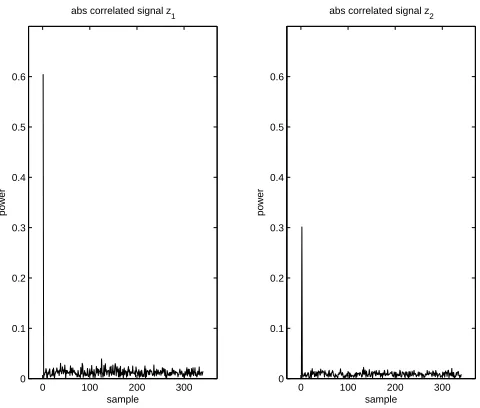
Most path search algorithms have a resolution of one or several chips. In [17] an algorithm is presented for W-CDMA systems that can also distin-guish between multipath components within a chip period. The algorithm has been intended for the mobile terminal (downlink). It is assumed that the channel has three paths, and exhibits Rayleigh fading without Doppler effects. The delay spread is smaller than the chip time. Two to thirty users are present in the cell.
The algorithm is based on the crosscorrelation of the received signal with a replica of the desired user signature. Then the result is manipulated with theTeager-Kaiser (TK) operator, which is defined in discrete time as follows:
ΨD[x(n)] =x(n−1)x∗(n−1)− 1
2(x(n−2)x
∗(n) +x(n)x∗(n−2)) (2.9)
This produces a signal with a number of peaks that correspond to the dif-ferent paths. Then square envelope detection is applied to this signal, after which noncoherent averaging is performed over a number of symbols. The first maxima in this signal correspond to the paths that are searched.
14 Literature study
2
It can be concluded from these simulations that the presented algorithm performs similar to MUSIC and performs better than MEDLL and PS. As the number of users increases in the cell (from two to thirty), the mance deteriorates. Also the pulse shape that is used influences the perfor-mance. The complexity of the algorithm is much lower than that of MUSIC.
2.5.1.9. Performance analysis of multi-path searcher for UE in W-CDMA systems
In [37] a path searcher is described that uses double-dwell serial search as well, as in [36]. The algorithm has been intended for usage in the mobile ter-minal (downlink) of a W-CDMA system. Slow frequency selective Rayleigh fading and Doppler effects occur while MAI is not taken into account.
2.5 Discussion of the papers 15
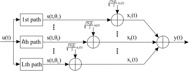
2.5.2 Maximum Likelihood-based path searchers
A second class of path search algorithms is based on aMaximum Likelihood
(ML) approach. In this set-up the received signal r(t) is first filtered by a matched filter and then sampled. Based on the matched filter output signal
y, a Maximum Likelihood function can be formulated. A parameter matrix is defined first as θ withτ = [τ11, . . ., τkl]T and α= [α11, . . ., αkl]T:
θ= [τ α] (2.10)
with θkl = [τkl αkl]. For a compact notation the shifted versions of the spreading waveformsskl(t) (see equation 2.2) are defined as:
s(t;θ) =
K
X
k=1
L
X
l=1
(skl(t)) (2.11)
The likelihood function can now be defined as follows:
Λ(θ;y) = 1
N0
"
2
Z
Do
<³sH(t;θ)y(t) ´
dt−
Z
Do
||s(t;θ)||2dt #
(2.12)
In (2.12) [·]H denotes the Hermitian operator. By maximizing the ML func-tion (or a proporfunc-tional cost funcfunc-tion) over the time interval with lengthDo, the estimates of the path delays are found:
ˆ
θM L(y)∈argmax θ {Λ(
θ;y)} (2.13)
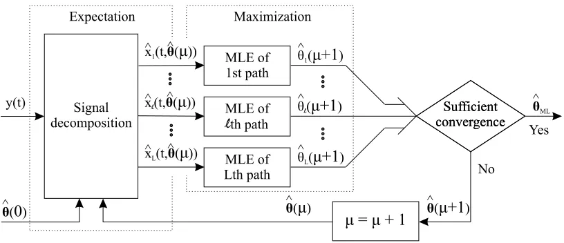
This maximization can be carried out by several iterative algorithms, such
asExpectation Maximization (EM) [8] [9] [10] [31] [5] and Alternating
Pro-jections (AP) [9]. Following the EM approach, the path parameters θ are
determined by maximizing (2.13). The advantage of ML-based algorithms is that they have a higher resolution than the power delay profile-based algorithms.
2.5.2.1. Channel acquisition for wideband CDMA signals
A method for selecting paths in a channel that is suitable for Wideband Code Division Multiple Access systems is described in [21]. The channel between the base station and the mobile terminal is modelled as a tapped delay line filter with a certain delay spread. Furthermore no Doppler effects occur and the fading type is slow frequency selective Rayleigh fading.
16 Literature study
2
mobile terminal coming into the cell. The question is how can the param-eters of the paths of the new user be estimated. Using knowledge of the structure of the MAI it is possible to reduce its impact.
The path search algorithm is based on a chip-matched filter that makes use of a pilot tone in the received signal. As the channel is estimated, the channel model is approached by a finite tapped delay line filter with all taps on equal distance of each other. This means that only the delay of the first tap (initial delay) needs to be estimated, as well as the gains of the taps. Using a Minimum Mean Square Error (MMSE) estimate for the sent sym-bols of the interfering mobile terminals, a Maximum Likelihood estimate of the parameters of the new user’s paths can be made. All taps are estimated at the same time (joint acquisition).
The second step of the algorithm is selecting the paths that contain the most energy. In order to do this a channel model is calculated with a lim-ited number of taps that shows the highest correlation with the estimate of the channel that was found earlier. Besides this correlation-based method another method for tap-reduction is presented. This method simply chooses the most significant taps from the estimated channel model. This method can be extended by also looking at the taps that lie in the direct vicinity of the most significant taps.
The performance of the algorithm is examined by a number of simula-tions. The performance measure that is used is the correlation between the reduced channel model (step 2 of the algorithm) and the estimated channel model (step 1 of the algorithm). This correlation is determined as a function of the Signal to Noise Ratio. It appears that the method that selects the most significant taps has the highest correlation for different values of SNR. The algorithm can suppress a limited number of interfering users, using the MMSE approach. Because of this the algorithm is MAI resistant. By re-ducing the number of users to be suppressed, the algorithm can be made less complex. This will deteriorate the performance of the algorithm, which leads to a tradeoff.
2.5.2.2. A sequential algorithm for joint parameter estimation and multiuser detection in DS/CDMA systems with multipath propagation
2.5 Discussion of the papers 17
character and no Doppler effects occur. The channel model exists of an im-pulse response that has been measured on five places in an urban area.
The algorithm has been based on a correlator and uses a preamble for initialization. A log-likelihood function is determined for valuing both the symbols that are sent and the parameters of the different paths. Given the complexity of this function, it is proposed to estimate the sent symbols for well-known parameters of the paths and to estimate the parameters of the paths as known symbols are sent. The path parameter estimation will be carried out by the Expectation Maximization algorithm (see also [31] for the JED-EM the method).
For this the conditional expectation of the log-likelihood function is de-rived. Next, this function can be maximized, starting from an initial value for the parameters of the paths. The maximization of the function is sub-divided into two iterative algorithms, one for valuing the delays and one for valuing the attenuation of the paths. Initialization takes place by using a preamble (pilot symbols).
The performance of the algorithm is analyzed by calculating the Root Mean Squared Error (RMSE) of the attenuation estimate, for the case of only one user and one path of which the delay is known. Also an expression is found for the bit error probability, for the case of strong MAI induced by the presence of other users. Using simulations, the influence of the number of the iterations used by the algorithm on the RMSE of the attenuation estimate is determined. It appears that the algorithm can also give a good estimate of the attenuation under the influence of strong MAI.
The bit error probability of the algorithm has also been simulated for strong MAI. In order to compare the results the bit error probability of a Rake receiver with perfect estimates of the delays and attenuation is used, as well as the bit error probability of a BPSK system with only AWGN. The simulations show that the algorithm is much less sensitive to ISI and MAI than the Rake receiver and it closely approaches the performance of the BPSK/AWGN receiver.
2.5.2.3. A new time-delay estimation in multipath
18 Literature study
2
In this paper MLE and AE are compared with each other. A channel is assumed that can be modelled by a tapped delay line, there are two multi-paths and the noise is AWGN. An expression for the MLE is inferred, based on the Power Spectral Density (PSD) of the signal. Also an expression is presented for the sample autocorrelation function for EM. Both methods provide an estimate of the path delays.
Next the AE method is generalized to a General Autocorrelation Esti-mator (GAE). This method is no longer dependent on the PSD of the sent symbols, which means that a pilot tone is no longer necessary. A cost func-tion is derived, that is to be maximized in order to value the delays. After estimation of the autocorrelation function the local maxima of this estimate can be determined. Using the cost function the time delays of the paths are then found.
The performance of the GAE algorithm is measured by calculating the MSE of the delay estimate. Simulations are carried out with the MSE as a function of the SNR, as well as simulations with the MSE as a function of the delay. For comparison the MLE and AE algorithms from the first part of the paper are used, as well as the CRLB. For low SNR values MLE seems to perform just as badly as AE. For higher SNR levels MLE performs consider-ably better than AE, but it requires more calculations than AE. Simulations show that GAE approaches the CRLB for both white and colored noise.
2.5.2.4. Iterative techniques for DS/CDMA multipath channel estimation
In [9] an algorithm is presented that uses a Maximum Likelihood approach in a W-CDMA system with several users (see also [10]). The algorithm will be used in the base station (uplink). It is assumed that there are ten users in the cell and that the channel has three paths within a certain delay spread. The tenth user has just arrived in the cell and the parameters of its paths are now to be valued. Rayleigh fading occurs with a slow, frequency selective character without Doppler effects. The MAI is modelled as colored Gaussian noise and an attempt is made to suppress it. The channel is modelled as a discrete tapped-delay line filter.
2.5 Discussion of the papers 19
In the paper two methods are presented for maximizing the ML-function. These methods are based on Expectation Maximization (EM) and Alter-nating projection (AP). Both methods have been formulated as an iterative algorithm and produce an estimate of the delay and attenuation of the paths of the new user.
With the presented algorithms several simulations have been carried out. The deviation (RMSE) between the estimates and the real values of the at-tenuation and delays of the paths has been examined. Also the chance has been defined that all parameters of the new user’s three paths are correctly valued. In the simulations the performances of the EM and AP algorithms are compared to those of a simple correlator from literature and the CRLB. Also the performances of the EM and AP algorithms are determined for the case they use the exact covariance matrix, instead of an estimated version.
From the simulations it becomes clear that the EM and the AP algo-rithms have a similar performance and approach the CRLB. The complexity of the calculations of the EM algorithm is considerably lower than those of the AP algorithm. On the other hand the AP algorithm requires less iter-ations in order to converge. Therefore a proposal is made to use the AP algorithm for initializing the EM algorithm.
2.5.2.5. Weighted RLS channel estimators for DS/CDMA signals in multipath
In [3] an algorithm is described that can be used for estimating multipath parameters in a W-CDMA system. No specific choice is made for using the algorithm in the base station or the mobile terminal. It is assumed that there are eight users in the cell. Rayleigh fading occurs with a slow, frequency selective character without Doppler effects. The channel is considered as a Finite Impulse Response (FIR) filter, that is constant over one symbol time.
The received signal is filtered and sampled. Then a Maximum Likelihood cost function is defined, that has to be minimized in order to calculate an estimate for the parameters of the channel. For this minimization a Recur-sive Weighted Least Squares (RWLS) algorithm is described. To make sure that the complexity of the calculations remains limited, a bank of parallel RWLS estimators is used.
20 Literature study
2
2.5.2.6. Multipath time-delay detection and estimation
In [24] an algorithm is presented for estimating the delay and the atten-uation of paths in a multipath system in a general sense. The presented algorithm is especially suitable for a channel in which the path delays are closely spaced. It is assumed that the channel imposes AWGN, no MAI or Doppler effects are mentioned.
The first step of the algorithm consists of matched filtering of the re-ceived signal. According to the reconstruction theorem the samples at the output of the matched filter can be expressed as a matrix multiplied by a weighing vector plus a noise vector. The indices of the components of the weighing vector that are nonzero, correspond to the delays of the paths. The required weighing factors are samples of an interpolation function, such as the sine cardinal function.
In case of oversampling with for example a factor two it is necessary to choose a reconstruction criterion for selecting the correct reconstruction function. Since the minimuml2 norm always leads to the same sine
cardi-nal function, it is proposed to choose the minimum l1 norm for this. The
minimization of this norm is formulated next and this turns out to be the so-called deconvolution criterion. By minimizing this expression, the path delays can be found.
2.5 Discussion of the papers 21
2.5.3 Subspace-based path searchers
A third group of path search algorithms is based on the covariance matrix of the received signal. First the baseband signal is correlated with the user signature and then sampled. The next step is to calculate an estimate of the covariance matrix of this signal.
By eigendecomposition of the covariance matrix, the eigenvectors of the signal subspace and the noise subspace can be found. In principle the signal subspace and the noise subspace are orthogonal and can therefore be sepa-rated from each other. In the papers that were found this orthogonality is exploited by respectively determining a Super Delay Profile and the use of a Toeplitz displacement.
This way the channel can be identified and the path delays can be de-termined. The algorithms have the advantage that they require much less knowledge of the user signatures of all the users in a cell (unlike the ML methods) and they can achieve a higher path delay resolution.
2.5.3.1. Multipath delay estimation using a superresolution PN-correlation method
A number of algorithms exist for multipath delay estimation with high res-olution. One of these algorithms is the superresolution Pseudo-Noise se-quence correlation method (SPM), based on MUSIC. In [11] a number of improvements for the SPM algorithm are proposed and the performance is examined. The paper does not address techniques specific for W-CDMA systems, but discusses the path searching problem in a broader context. Instead of analyzing the influence of MAI, the effects of a narrowband in-terferer are studied.
The SPM algorithm is based on a correlator that calculates the correla-tion of the received signal with the chipping sequence. For the delay profile vector that is determined this way, an expression is inferred:
y=
L
X
l=1
hlr(τl) + ˜w (2.14)
In (2.14)r(τ) denotes the steering vector containing the autocorrelation of the user signature. In short:
y= Γg+ ˜w (2.15)
22 Literature study
2
Also an expression is found for the covariance matrixRy of vector y:
Ry = ΓGΓH+Rn (2.16)
In (2.16) G=E{ggH} and Rn =E{w˜w˜H} =σ2R0. By estimating Ry and determining the eigenvectors v of this matrix a super resolution delay profile (SDP) can be determined as:
SDP(τ) = r
H(τ)R
0−1r(τ)
PL
m=M+1|rH(τ)vm|2
(2.17)
With M as the number of samples at the output of the correlator. An estimate of the covariance matrix can be made for time-variant channels as well (slow frequency selective fading) to find the paths.
In many cases the covariance matrix can not be estimated precisely enough. This can be solved by exploiting the relation between the used carrier frequency and this matrix. By switching the carrier frequency while the PN sequence is sent (both in the transmitter and receiver), several es-timates of the matrix can be made. Finally a frequency smoothed (FS) estimate of the covariance matrix is made by averaging these estimates.
If the jumps in the carrier frequency are not chosen carefully, it is pos-sible that FS hampers the performance of SPM. In order to prevent this, a proposal is presented to choose the jumps in the carrier frequency at ran-dom: Random Frequency Smoothing (RFS). This technique is more able to find the paths than FS, even for a small number of jumps in the carrier fre-quency. The performance of the SPM/RFS algorithm has been investigated extensively in an artificial pond with a transducer and a hydrophone.
2.5.3.2. A Toeplitz displacement method for blind multipath esti-mation for long code DS/CDMA signals
2.5 Discussion of the papers 23
The received signal is chip-matched filtered and then sampled at the chip rate, the matched filter outputy(n) is:
y(n) = K
X
k=1
Ck(n)Hkbk(n) +w(n) (2.18) In (2.18)Ck(n) denotes a spreading code matrix, containing all spreading sequences. The channel is modelled asHkand the sent data asbk(n). Next an expression is inferred for the covariance matrixRy of the received signal from userk.
Ry =σk2Sk(n)Ck(n)HkHkHCkH(n)SkH(n) +RI(n) +Rw(n) (2.19) With Sk as a matched filtering matrix. By performing a Toeplitz dis-placement ofRy the noiseRw(n) and interference RI(n) can be removed:
Rh =SCk
+
HkHkHSCk
+H
−SCk
−
HkHkHSCk
−H
(2.20)
The paper argues that the eigenvectors of this covariance matrix Rh contain the estimate of the channel parameters. Eigendecomposition of Rh leads to a matrix V containing the eigenvectors. The channel estimate is determined by:
ˆ
hk= arg min
||h||=1Trace{H
HPH
} (2.21)
with H= [(SCkHk)+,(SCkHk)−] and P=I−VVH
24
L
it
er
a
tu
re
st
u
d
y
2
ref. system channel fading delay Doppler scenario MAI modelling channel evaluation of path
type model type spread effects and suppression estimation paths selection
[21] w-cdma tapped Rayleigh not none uplink MAI MMSE-ML determining select delay fading specified 10 users suppresion technique power maxima line slow + L paths with MMSE in paths with Max-Lr
freq. sel. technique technique
[25] w-cdma filter in not 20µs none downlink MAI is correlation calculate PDP setting discrete specified K users modelled of P-CPICH (non-coher. threshold for time L paths as AWGN with replica averaging) max. in PDP [13] w-cdma not Rayleigh not fd= downlink none correlation PDP based, select ten
specified fading specified 5.6 Hz 1 user of common 3 man. tables strong. paths 2 paths pilot symbols for path data from PDP [28] w-cdma L-path Rayleigh not v = uplink none correlation accumulation thresholding
model fading specified 30 km/h 1 user of (coherent + slow + 120 km/h L paths DPCCH non-coh.)
freq. sel. sq. env. detect.
[18] w-cdma ITU-R Rayleigh not fd= uplink none correlation calculate thresholding: Veh. B fading specified 80 Hz 1-2 users (fast TPC) of pilot PDP PDP - 4 L-path slow + 320 Hz 1-4 paths symbols (coherent strongest model freq. sel. with replica averaging) paths [12] utra- ITU-R Rayleigh not none uplink none correlation calculate thresholding
fdd Veh. B fading specified K users of pilot PDP PDP
-3GPP slow + L paths symbols WMSA
specs freq. sel. with replica filtered signal [4] w-cdma not Rayleigh not none uplink partial correlation calculate PDP thresholding
specified fading specified 10 users MAI with select with respect freq. sel. 6 paths suppression spreading subset of to strongest
sequence paths by power path
[36] w-cdma Jakes’ Rayleigh not v = downlink none correlation square thresholding? model fading specified 3 km/h K users of envelope
slow + 30 km/h 2 paths CPICH detect. + post freq. sel. 160 km/h coh. summ. detect. integr.
[8] w-cdma meas. Rayleigh < Tb none uplink MAI correlation ML-JED Expectation-impulse fading 6 users suppression of Maximization response slow + 3 paths with preamble
at 5 freq. sel. ML-JED
2.
5
D
is
cu
ss
io
n
of
th
e
p
ap
er
s
25
ref. verification signal performance compared cost
source measure with
[21] simulations BPSK, SF = 31, correlation of opt. correl., sync (9 chips) estimated channel conventional
and reduced channel algorithm
[25] simulations not specified a single PDP no 1689 byte comparison 32.8 MIPS
[13] simulations QPSK, BLER as function conventional specified in of SNR receiver + great detail perfect rcv. [28] simulations SFc = 256 Pd,PmandPf, no
SFd= 64 mean acquisition comparison
Np= 9 time
[18] simulations QPSK requiredEb/N0 of no
field specified in the transmitter for a comparison experiments great detail BER = 10−3
[12] simulations 12.2 kbps MSE of noise var. conv. recv. 6 MIPS RRC pulse req.Eb/N0 transm. thr = PDP - 4
for a BER = 10−3 thr = PDP - 6
[4] simulations not specified BER as function of conv. rcv. + SNR rcv. selecting
fixed paths [36] simulations not specified ROC no
comparison
[8] simulations not specified RMSE of perfect Rake (BPSK?) amplitude estim.
BPSK/
26
L
it
er
a
tu
re
st
u
d
y
2
ref. system channel fading delay Doppler scenario MAI modelling channel evaluation of path
type model type spread effects and suppression estimation paths selection
[16] general tapped not not none both none GAE determine find path case delay specified specified links local maxima delays
line K users of estimated with cost
2 paths autocorrelation function [17] w-cdma sub- Rayleigh < Tc none downlink MAI correlation squared maximum
chip: fading 2-30 users modelled and Teager envelope selection overlap. 3 paths as Kaiser det. +
non-paths AWGN operation coh. averag.
[11] general path slow + <0.2Tc none high path no MAI, estimation calculate case delay freq. sel. resolution only of
super-variation 3-4 paths narrowband covariance resolution interference matrix delay profile
[24] general not not not none link not none deconvol. minimize case specified specified specified specif. method with using
close K users with the min.
paths 3 paths min. L1-norm L1-norm
[37] w-cdma not Rayleigh not v = downlink none correlation sq. envelope thresholding? specified fading specified 160 km/h K users of detect. + post
slow + L paths CPICH detection
freq. sel. coh. summ. integration
[9] w-cdma discrete Rayleigh <0.5Ts none uplink MAI is matched ML criterion maximize tapped fading 10 users modelled filtering of using EM delay slow + 3 paths as colored training and AP line freq. sel. Gauss. noise sequence
[6] w-cdma not Rayleigh << Ts none both MAI is estimation Toeplitz specified fading links described of Displacement
slow + 8-12 users in channel covariance and eigen freq. sel. L paths model matrix decomposition
[3] w-cdma FIR Rayleigh <16Tc none both none ML cost minimize
filter fading links function using
slow + 8 users RWLS
2.
5
D
is
cu
ss
io
n
of
th
e
p
ap
er
s
27
ref. verification signal performance compared cost
source measure with
[16] simulations not specified MSE of delay MLE algorithm + CRLB [17] simulations QPSK, rect chance of MUSIC +
RRC pulses detecting all paths MEDLL + Walsh SF = 64 PS [11] measurem. transducer and several PDP’s SPM +
hydrophone SPM-FS
[24] simulations linear FM error in delay and CRALS + amplitude POCS estimates
[37] simulations not specified ROC no
comparison
[9] simulations Gold seq. (31 RMSE of amp. and simple bits), SNR = delay, chance of correlator + MAI = 10 dB detecting all paths CRLB [6] simulations not specified MSE of channel algorithm
estimate from literature [3] simulations Walsh- ? SUMF +
Hadamard MMSE
28 Literature study
2
2.6
Selection of three algorithms
One of the questions within the AWGN project (Chapter 1) is: to what extent will it be useful to switch between different types of algorithms for the path search function? In order to get a clear picture of the different techniques for the implementation of the path search algorithm a number of papers has been discussed in the literature study. The algorithms that were found have been compared with each other (Section 2.4) and have been dis-cussed in detail in Section 2.5. The algorithms have been classified in three classes, based on the similarities discovered among the various algorithms. Three algorithms are now selected for further research. Two algorithms will be implemented: the Power Delay Profile-based path searcher (Chap-ter 4) and the Maximum Likelihood-based path searcher (Chap(Chap-ter 5). The subspace-based algorithm will be discussed in theory only, see Appendix B.
The first class consists of the Power Delay Profile-based algorithms (Sub-section 2.5.1). These algorithms correlate the received signal with a replica of the user signature. Next a Power Delay Profile (PDP) is calculated based on this correlated signal, from which the strongest paths are selected us-ing a threshold value. In [18] extensive simulations and measurements were carried out with this method. The implementation of the PDP-based path searcher will be performed using [25], as it describes its principle in great detail (see Chapter 4). Improvement of this algorithm will then be possible by calculating the threshold value according to [12].
The second group of algorithms is based on a Maximum Likelihood ap-proach (Subsection 2.5.2). The received signal is filtered first with a matched filter and then sampled. Based on this signal a Maximum Likelihood Esti-mate of the path delays is formulated. By maximizing the MLE function the delays can be determined. This maximization is carried out in [8], [16], [10] and [9] using Expectation Maximization, as well as in [31] and [5]. The MLE-EM method provides good performances for a low computational cost and is therefore selected for optimizing the Maximum Likelihood function. The implementation of the MLE-EM path searcher will be based on [8], as it describes its principle in great detail (see Chapter 5).
3
Simulation environment for
path search algorithms
3.1
Multipath channel models
Now that the various options for the implementation of the path search algorithm have been investigated in the literature study, the selected al-gorithms will be implemented. In order to set up meaningful simulations with these algorithms first a number of channel models are analyzed in this section. Also scenarios will be formulated in the next section that describe the conditions in the channel between the transmitting base station and the receiving mobile terminal.
The main features of the channel model become clear from formula (2.3), which is repeated here for convenience:
hk(t) = L
X
l=1
αk,l(t)δ(t−τk,l(t))ejφk,l (3.1) In equation (3.1)L indicates the number of paths for userkin the channel and αk,l(t) andτk,l(t) indicate respectively the path attenuation and delay. The formula describes that the channel can be viewed as a sum ofL multi-paths, each having a specific delayτk,l(t) and attenuation αk,l(t).
During the literature study various channel models were encountered that try to capture the behavior of this Rayleigh fading channel between the base station and the mobile terminal. In the next subsections the models will be discussed that are used in the papers from the literature study. They include Jakes’ channel model (Subsection 3.1.1), the L-path channel model (Subsection 3.1.2) and models from ETSI (Subsection 3.1.3).
30 Simulation environment for path search algorithms
3
3.1.1 Jakes’ channel model
A classic model for Rayleigh fading that is widely used (e.g. in [36] and [19]) can be found in [29]. The field is modelled as:
E(t) =Re[T(t)ejωct] (3.2)
with
T(t) = √E0
N
N
X
n=1
ej(ωmtcosαn+φn) (3.3)
It is assumed that the angles of arrival are uniformly distributed, αn = 2πn/N with nin [1, N]. The Doppler frequency is denoted asωm. A prob-lem of this model is that it is not Wide Sense Stationary. This issue is analyzed in [32] and an improvement of the Jakes’ channel model is pro-posed. Also a new block scheme for the channel simulator is presented.
Unfortunately, part of the second order statistics of the improved Jakes’ channel model is not modelled correctly. In [7] the autocorrelation and cross-correlation of the signal quadrature component and the autocross-correlation of the squared envelope are analyzed. In [20] the correlations of the Jakes’ channel model are investigated as well. Especially the distribution of the scatterers in the channel are investigated.
Another drawback of the Jakes’ channel model is that it does not pro-duce uncorrelated paths under all circumstances. To solve this problem, improvements are proposed in [15].
3.1.2 L-path channel model
In most of the papers the L-path channel model was used: [28], [18], [8] and [11]. This model is also referred to as the tapped delay line channel model in [21], [25], [16], [9] and [3]. It is described in [34] as:
hk(t) = Lk
X
l=1
hk,l(t)δ(τ −τk,l(t))ejφk,l (3.4) Both the attenuation and delay can change over time. This means that a path can change in length (and thus delay), it can disappear (hk,l(t) = 0 for certain values oft) or a new path can appear (hk,l(t)>0 for certain values oft).
3.1 Multipath channel models 31
Scattering, withhk,l(t) as an independent Rayleigh distributed random vari-able. The Rayleigh distribution is defined in [34] and [27] with the following probability density function:
p(r) =
(
r σ2e
−r2
2σ2 0≤r ≤ ∞
0 r <0 (3.5)
3.1.3 3GPP and ITU-R Vehicular B channel models
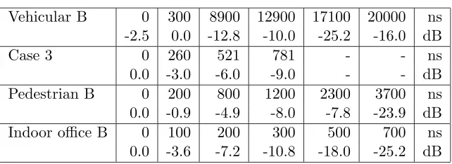
In [12] one of the channel models that is used is the model specified by 3GPP (see ETSI document [1]). Of this model Case 2 and Case 3 are used for simulations. In [1] the multipaths are defined in terms of their relative delay and attenuation, the Case 2 channel model has three paths and the Case 3 channel model has four paths. These models also include Doppler effects (for respectively v = 3 km/h and v = 120 km/h), but in [12] these models were made stationary.
The other channel model that is used in [12] (and in [18] as well) is the ITU-R Vehicular B model (see ETSI document [23]). It models a rural or suburban outdoor macro cell environment at a maximum velocity ofv= 500 km/h. Again, the model is made stationary in [12]. It consists of a tapped delay line and has six paths, of which the delay and attenuation are defined. Also traffic models are established for the services that are carried by the links in the cell (e.g. speech and web browsing).
The propagation effects are divided in three groups. The first group is formed by the effects that cause the mean path loss. The path loss is modelled as:
L= 40(1−4·10−3∆hb) log10(R)−18 log10(∆hb) + 21 log10(f) + 80dB (3.6)
32 Simulation environment for path search algorithms
3
3.1.4 Measurements of channel impulse responses
An alternative for modelling the channel’s impulse response is the use of actual measurements of its impulse response. In [8] 500 different channel impulse responses have been obtained in urban areas. For each simulation a channel impulse is selected randomly from these measurements.
In [18] simulations are accompanied by laboratory experiments. Both are used to optimize the path searcher’s parameters. Finally field experi-ments are carried out to investigate the performance of the optimized path searcher. For this a measurement vehicle has been driven along two different courses (of length 0.6 and 1.1 km) at a number of speeds (20 to 40 km/h). The first course is located in a factory area and the second course near a residential area. The corresponding power delay profile measurements are shown as a function of time in [18] and clearly display the different charac-teristics of the two radio environments.
In the simulation environment that is available the L-path model is used. The fading type can be set to either Rayleigh or AWGN. Also two vectors of length L can be used to set the channel parameters for user k in terms of the path delaysτk,l and path gains αk,l. The values that will be used for these channel parameters will be discussed in the next section.
3.2
Scenarios for simulations
As previously noted, it is necessary to analyze the channel model first in order to set up meaningful simulations with the path search algorithms from the literature study. Also scenarios need to be formulated that describe the conditions in the channel between the transmitting base station and the receiving mobile terminal. This section gives an overview of likely scenarios, in Subsection 3.2.1 the characteristics of an outdoor rural area are discussed, the outdoor urban area is analyzed in Subsection 3.2.2 and Subsection 3.2.3 describes an indoor office environment. Finally two effects are commented upon in Subsection 3.2.4. These are variable path delays over time and the so-called birth-death sequence of paths. Table 3.1 gives an overview of these scenarios . More information on scenarios can be found in [1] and [23].
3.2.1 Outdoor rural area
3.2 Scenarios for simulations 33
Scenario cell size transmit path r.m.s. delay mobile
power loss spread speed
Indoor office area pico / micro low variable 35 - 100 ns walking speed
Outdoor urban area micro / macro low R−6 R−4 45 - 750 ns vehicle speed
Outdoor rural area macro high R−2 370 - 4000 ns vehicle speed
Scenario Doppler fading shadowing
effects effects effects
Indoor office area v= 3 km/h Ricean, Rayleigh log-normal 12 dB
Outdoor urban area v= 50 km/h Ricean, Rayleigh log-normal 10 dB
Outdoor rural area v= 120 km/h Rayleigh log-normal<10 dB
Table 3.1: Scenarios for mobile terminal environment
and obstructions in the paths of the channel, as the terrain is mostly flat. The fading type is mainly Rayleigh and shadowing effects are modelled by a log-normal distribution with a standard deviation below 10 dB. Doppler effects occur as the mobile terminal can have speeds up to 120 km/h. This scenario corresponds to the Vehicular B channel parameters in Table 3.2.
3.2.2 Outdoor urban area
The outdoor rural area is divided into smaller cells (micro to macro cells) that are covered by base stations with low transmit powers. The root mean squared delay spread lies between 45 and 750 ns. The outdoor urban area is characterized by a range of path losses (R−6 to R−4), depending on the
number of high buildings, base station antenna height, obstructions by trees etcetera. The number of scatterers and obstructions in the paths of the channel can vary. The fading type can be both Ricean and Rayleigh, shad-owing effects (see [34]) are modelled by a log-normal distribution with a standard deviation of 10 dB. Doppler effects occur as the mobile terminal can have speeds up to 50 km/h. This scenario corresponds to the Case 3 and Pedestrian B channel parameters in Table 3.2.
3.2.3 Indoor office area
34 Simulation environment for path search algorithms
3
Vehicular B 0 300 8900 12900 17100 20000 ns -2.5 0.0 -12.8 -10.0 -25.2 -16.0 dB
Case 3 0 260 521 781 - - ns
0.0 -3.0 -6.0 -9.0 - - dB
Pedestrian B 0 200 800 1200 2300 3700 ns 0.0 -0.9 -4.9 -8.0 -7.8 -23.9 dB Indoor office B 0 100 200 300 500 700 ns 0.0 -3.6 -7.2 -10.8 -18.0 -25.2 dB
Table 3.2: Four path delay and power vectors
3.2.4 Propagation conditions
In most of the papers that were found during the literature study it was assumed that the channel is stationary, or at least stationary over one sym-bol period. This is not necessarily true, as both hk,l(t) and τk,l(t) can be functions of time. As the mobile moves from one location the next within a cell, or if an object passes the mobile terminal nearby, it is possible that changes occur in the path parameters or even in the number of paths.
The path searcher needs to be sensitive to changes in path delays after it has converged to an estimated path delay for the first time. If for example, the delay of thelth pathτ
k,l(t) changes, it needs to be estimated again. An example of a changing path delay is provided in [11].
Another possibility is that the number of paths changes over time. This can happen for example as the mobile terminal is moving from a rural area into an urban area. The number of scatterers will increase, causing a larger number of paths. This can be described as a change of thelth path attenu-ation hk,l(t) from zero to a certain value. This is denoted as the ’birth’ of a path. The opposite, hk,l(t) goes to zero, is called the ’death’ of a path. These effects are described in [1].
3.2.5 Modifications to the simulator
3.2 Scenarios for simulations 35
In the header file of the downlink receiver (see Appendix C.2) the path searchers’ abstract base classes need to be included as well as the various ver-sions of the path searcher (such as the path searcher classes in Appendixes C.4 and D.1). Using a pointer to the abstract base class, it is possible to switch between different implementations of the path searcher in the source file of the downlink receiver (see Appendix C.3).
In order to support the simulations discussed in Section 3.2.4 a second basestation is added to the simulator. This way the situation shortly before a handover can be simulated: the mobile terminal is at the boundary of the first basestation’s cell and detects a second base station with a signal strength equal or greater than that of the first basestation.
4
A Power Delay Profile-based
path searcher
4.1
Introduction
As part of the literature study several papers have been discussed that an-alyze so-called Power Delay Profile (PDP)-based path searchers. One of these algorithms [25] has been selected for implementation. This chapter discusses the PDP-based path search algorithm and its implementation in detail. The algorithm consists of five functional blocks that will be discussed in the following paragraphs.
The algorithm correlates the complex received signal with the pilot tone from the Primary Common Pilot Channel (P-CPICH). By calculating the correlation over the length of a frame, a delay profile is found (Section 4.3.1). This delay profile is averaged over a number of previous frames (Section 4.3.2), to suppress fast fluctuations induced by interference. This results in a Power Delay Profile (PDP). The local maxima in the PDP are selected using a three-points method (Section 4.3.3). The height of these maxima (attenuation) is compared with a threshold (Section 4.3.4). If it exceeds the threshold a path is detected and the associated delay is forwarded to a Rake receiver (Section 4.3.5). The PDP path searcher is shown in Figure 4.1.
h(t) average thresholdset
select
maxima compare
code generator
x(t) r(t)
s(p)
y(n,m) z(n,m)
Threshold
z (n,m)max delays
source channel
ADC r(p)
sampling
Figure 4.1: Power Delay Profile-based path searcher
38 A Power Delay Profile-based path searcher
4
4.2
Setting up interfaces and structuring the
al-gorithm
A model of the downlink in a UMTS system is available in C++. As the algorithm will operate in the mobile terminal it needs to communicate with the downlink receiver. The downlink receiver provides the path searcher with both the conjugate of the user signature and the received signal. It also sets the spreading factor of the path searcher as it is initialized. The path searcher returns the number of paths and their delays to the downlink receiver. Based on the number of paths and the path delays the downlink receiver can set the Rake fingers accordingly.
The path searcher algorithm has been implemented in Matlab at first to gain more insight in its structure. As the model of the UMTS downlink is available in C++ the PDP path searcher needs to be modelled in C++ as well. The number of modifications to the downlink receiver can be kept to a minimum by creating a virtual base class for the path search algorithm (see Appendix C.1). A number of set() and get() functions handle the commu-nication betwe