G E N E R A L
REFERENCE
I\,/)
A
N
U
A
L
This manual is published by the UNIVAC@Division in loose leaf format as a rapid and complete means of keeping recipients apprised of UNIVAC Systems developments. The UNIVAC Division will issue updating packages, utilizing primarily a page-for-page or unit replacement technique. Such iss uance w ill provide notification of hardw are and/or software chan ges and refinements. The UNI\' AC Di'r./ision reser'ves the right to ~a ke such additions, corrections, and/or deletions as, in the judgment of the UNIVAC Division,are required by the development of its respective Systems.
@ REGISTERED TRADEMARK OF THE SPERRY RAND CORPORATION © 1963 • SPERRY RAND CORPORATION
PREFACE
This ma.nual provides a comprehensive source of information concerning the UNIVAC 490 Real-Time System: its basic units; its wide variety of configurations and applications; its uniquely efficient instructions, and the programming packages which make the use of the system outstandingly practical and economical.
UP-3900
UNIVAC 490 SPURT
Rev. 3 1SECTION: PAGE:
1.
CONTENTS
1. CONTENTS 1-1 to 1-4
2. INTRODUCTION 2-1 to 2-2
3. GENERAL DESCRIPTION 3-1 to 3-5
A. Communication Capabilities 3-2
B. Mass Storage Faci!ities 3-2
C. Real Time Central Processor Design 3-2
D. Input/Output Equipment 3-2
E. An Advanced, Comprehensive Programming System 3-3
F. Dependabi I ity of Operation 3-3
4. COMPONENT DESCRIPTION 4-1 to 4-18
A. Central Processor 4-1
8. Clocks
4-3
C. Subsystems 4-4
5. PROGRAMMING IN SPURT 5-A-l to 5-E-52
A. COMPUTER ELEMENTS RELATED TO PROGRAMMING 5-A-l
8.
C.
1.
The Computer Word 5-A-l2. Addressing 5-A-3
3. The Computer Instruction 5-A-3
CENTRAL PROCESSOR
1. Storage Section
2.
Contra I Section3.
Arithmetic Section4.
Input/Output Section5.
RegistersTH E SPURT ASSEM8LY SYSTEM
1.
The SPURT Statement 2. The SPURT Coding Form5-8-1 5-8-1 5-8-1 5-8-1 5-8-1 5-8-1
5-C-l 5-C-l 5-C-l
1 2 Rev. 2 UNIVA~
q 8 D
5~URTSEC TION: PA GE:
D. SPURT INSTRUCTION FORMAT
1.
The General Operand2. Comments on the Presentation of the 8asic SPURT Instructions
E. 8ASIC SPURT INSTRUCTIONS
1.
Data Transfer Instructions2.
Shift Instructions3.
Comparing Instructions 4. Jump Instructions 5. Modifying Instructions6.
Subtraction7.
Addition8. Multiplication and Division
9.
Logical and Selective Instructions 10. Miscellaneous Instructions 11. Assembler Macro-Operations 12. 8 as i c In p u t/ 0 u t put Ins t r u c t ion s6. SPURT INPUT/OUTPUT UNDER EXECUTIVE CONTROL A. STATUS CHECKING
1. E r ro rAn a I y sis 2. Examples of CKSTAT
B.
UNISERVO IIA MNEMONICS1.
UNISERVO IIA Tape Operations2.
UNISERVO IIA Status WordsC. UNISERVO IIIC MNEMONICS
1.
UNISERVO IIIC Tape Operations2.
UNISERVO IIIC Status WordsD. UNISERVO IliA MNEMONICS
1. UNISERVO lilA Tape Operations
2.
UNISERVO IliA StatusE. FLYING-HEAO-880 DRUM MNEMONICS
1. Flying Head-880 Drum Operations 2. Flying Head-880 Drum Status Words
F. HIGH-SPEED PRINTER MNEMONICS
1.
High Speed Printer Operations2.
High-Speed Printer Status WordsG
CARD MNEMONICS1. Card Operations 2. Card Status Words
5-0-1 5-0-1 5-0-5 5-E-l 5-E-l 5-E-2 5-E-6 5-E-7 5-E-9 5-E-ll 5-E-14 5-E-16 5-E-25
5-E-33
5- E-35 5-E-406-A-i
to 6-i-26-A-l
6-A-2
6-A-3
6-8-1 6-8-16-8-3
6-C-l 6-C-2 6-C-4 6-0-1 6-0-2 6-0-46-E-I
6-E-l
6-E-3
6-F -1 6-F-2
6-F
-3
~-G-1 6-G-2
6-G-8
U P-3900
UNIVAC 490 SPURT
Rev. 2 1 3SECTION: PAGE:
H.
FASTRAND MNEMONICS 6-H-lL
FAST RAN0
Operations 6-H-22. FASTRAND Status Words 6-H-3
3.
FASTRAND Addressing 6-H-4I. PAPER TAPE MNEMONICS 6-1-1
L Paper Tape Operations 6-1-1
2. Paper Tape Status Words 6-1-2
7. CONSOLE PRINTER CONTROL 7-A-l to 7-8-2
A. CONSOLE OUTPUT OPERATIONS 7-A-l
8. CONSOLE INPUT OPERATIONS 7-8-1
8. PROGRAM DEFINED MACRO OPERATIONS 8-1 to 8-5
A. DEFINING A MACRO OPERATION 8-1
L The MACRO Statement 8-1
2. The ENDMAC Statement 8-2
3" Variable Parameters 8-2
4" Examples of MACRO Definition 8-2
B, CALLING A MACRO o "I
0-')
L The Call Line 8-3
2" Examples of Macro Call Line 8-3
C.
NESTiNG OF MACROS 8-4D. LABEL REFERENCE WITHIN MACROS 8-5
9, PROGRAM PREPARATION 9-1 t09-16
A, SPURT REQUIREMENTS 9-1
L The Program Header 9-1
2. Allocation 9-1
8. REX REQUIREMENTS 9-5
L The Executive Information Region 9-5
2. Declaration of Facility Requirements 9-7
3. Drum and FASTRAND Statement 9-11
4.
Text Statement 9-125.
Program Segmentation 9-131 4 Rev, 3
UNIVAC 490 SPURT
UP-3900SECTION: PAGE:
10. PROGRAM TESTING AND CORRECTION A. SPURT OUTPUTS
l.
Paper Tape Output 2. High Speed Printer Output3.
High Speed Printer Output On Magnetic Ta pe4.
Magnetic Tape Output5.
Concurrent High Speed Printer and Magnetic Tape Output8, PROGRAM TESTING ROUTINES L Program Testing Operations
2.
Utilizing Program Testing RoutinesC. CORRECTION PROCEDURES
1, Card Correction Procedures
2.
TheLl
Corrector3" The Card Image Corrector Routine - CIMCO
D. CODED ERROR OUTPUT DURING ASSEM8LY
11. SYSTEM PROCEDURES
12. COBOL
13. SORT
14. MISCELLANEOUS ROUTINES
A.
RMOPL II(Routine for Maintaining an Object Program Library)
1.
System Requirements2.
Tape Composition3.
Operations Performed4.
Parameter CardsB.
MITAR II(Master Instruction Tape Assembly Routine)
1. System Requirements 2. Executi ve Se~uence
3. Tape Composition 4. MITAR Card Parameters
10-A-1
to10-0-2
10-A-1
10-A-2
10-A-3
1O-A-5
10-A-5
10-A-6
10-B~1
10- 8-1
10-8-4
10-C-1
1O-C-1
10-C-2
lO-C-3
10-0-1
14-A-l
14-A-l
14-A-l
14-A-2
14-A-2
14-8-1
UP-3900
UNIVAC 490 SPURT
C. CATUT
(Card to Magnetic Tape Utility Routine)
L System Requirements
2.
Program Structure3.
Card Input Composition and Arrangement4. Description of Routines and Subroutines in CATUT
D. PRINTAPE
(Magnetic Tape to High Speed Printer Utility Routine)
1.
System RequirementsE. TRACE IV
(Instruction Monitoring Routine)
1. System Requirements
2.
Output Format3.
Operations Performed 4. P aramete rsF. RMASL
(Routine for Maintaining a Source Language Library
1. System Requi rements
2.
Input Formai3.
Library Tape Format 4. Operations Performed5.
Parameter CardsG. CIMCO
(Card Image Corrector Routine)
1.
System Requ i rements2.
Operations Performed3.
Correction Deck FormatH. CONVERSION, EDITING, AND ARITHMETIC ROUTINES
1.
Conversion Routines2.
Ed iti ng Routi nes3. Floating Point Routines
4.
0
0 ubi e Pre cis ion A r i th met i c R 0 uti n e s5. Fie Idata Arithmetic Routines
APPENDICES
A. Computer Instructions D. Peripheral Subsystems
Rev. 2 1
SECTION: PAGE:
14-C-l
14-C-l14-C-l
14-C-1
14-C-6
14-0-1 14-0-1 14-E-l14-E-l
14-E-1
14-E-1
14-E-3 14- F-114-F-1
14-F-l
14-F-2
14-F-2 14-F-314-G-l
14-G-1
14-G-l14-G-l
14-H
-1
14-H
-3
14-H
-22
UP-3900
UNIVAC 490 SPURT
2 1SECTION: PAGE:
2. INTRODUCTION
A. REAL TIME, BATCH PROCESSING, AND CONCURRENT OPERATIONS
1. Real Time
Real time computers were originally developed for military purposes: to aim, track, and guide ballistic missiles; to receive, store, analyze, and provide useful results from vast radar or other information gathering net works so as to provide the basis for timely decisions on the part of human beings - decisions which could, when required, be acted upon almost instantly at locations
thousands of miles removed from their source.
The essential characteristics of real time computers are that they can store enormous masses of information; that they can access, or reach, and act upon, any item or group of items of the informa-tion within thousandths of a second; that they can receive and transmit data from and to small or large numbers of remote points in extremely short periods of time; that they can automatically assign priorities to many different operations so that action and response take place in proportion to the urgency of the need.
The expression real time is applied to computers of this kind because thay are capable of keeping
pace in their operations with the occurrence of events which follow one another with great rapidity and which may even occur sim ultaneously.
The U ni vac Division of the Sperry Rand Corporation has been an outstandingly successful pioneer in the development of real time computers and realized very early the tremendous potentials of their application to business situations. The result of this realization and of the ensuing development work is the UNIVAC 490 Real-Time System which makes it possible for modern management to take the fullest advantage of modern management techniques. Because it provides proper input/output devices for every type of business transaction, business events may be entered into the system, stored, located, related to other events, acted upon at the time of occurrence. Management by excep-tion is made possible on a truly current basis, in ample time to correct deviaexcep-tions from plan, wheth-er these involve availability of working capital, sales forecasts, manning and machine scheduling, inventory levels, receipts and shipments of materials, operating costs, or controls.
2
SECTION:
2
UNIVAC 490 SPURT
UP-3900PAGE:
The question is: how can a data processing system be made to provide all of these advantages in such a way as to approach the maximum utilization of the equipment employed, the highest return from the money expended for it, and therefore a correspondingly satisfactory increase in the profitability of the enterprise.
The answer is provided in the UNIVAC 490 Real-Time System in this manner:
2. Real Time and Batch Processing
The requirements for real time action are known frequently to occur in peaks and valleys. In many businesses these requirements tend to increase from early morning through the middle of the day and to taper off from then on. In other businesses the occurrence of these demands may be sporadic. It makes no difference. The UNIV AC 490 Real-Time System is so designed that it will automatically, as its facilities are freed from the dynamic demands of real time processing, load them up with the ordinary day to day back log of less urgent work -of the familiar batch processing type - typically, the sequential processing of sequentially ordered files such as accounts receivable, payable, or payrolls.
3. Concurrency of Operations
The great point is that the UNIVAC 490 Real-Time System is at no moment necessarily committed to real time operations or to batch processing operations exclusively. Both may proceed concurrently and several kinds of each may proceed concurrently under the control of an internally stored execu-tive program. But the real time operations always have priority and the system will assign its facilities as these priorities require, relinquishing them to other activities, such as engineering calculations or normal business processing tasks, as soon as they are no longer needed to keep pace with real time events.
In this way maximum use may be made of the components of any desired configuration of the UNIVAC 490 Real-Time System; and the ad van tages of its enormous storage capaci ty, speed, flexibility, and communications capabilities may be obtained at a low cost per unit of work accomplished.
To sum up, it should be said that experience indicates that the UNIVAC 490 Real Time System will quite probably outperform by a wide margin any other system of its kind in a wide range of applications.
The fact that it can actually do so in any particular situation can be established beyond doubt only by investigation and analysis. This fact has already been established many times and is being
UP-3900
UNIVAC 490 SPURT
3SECTION: PAGE:
3. GENERAL DESCRIPTION
For years there has been an urgent need for a business data processing system specifically designed to meet the steadily increasing pressures of costs vs. profits, of competition, of the need for radically improved communications, for improved service to customers, for more efficient inventory management, for more effective controls -- for 'improved over all capability to cope with the constantly growing complexity, diversity, wide spread nature, and sheer size of modern business.
The UNIVAC 490 Real-Time System is the first and only system specifically designed to meet these needs and which has proved in daily use that it does meet these needs, and more, at an entirely reasonable cost. It' is by a long way the most versatile and the most comprehensive data processing system yet produced.
The system provides the most effecti ve in strum ent in existence for the centralized control of
decentralized operations. The same characteristics which account for this, account also for its other advantages, which are many. These characteristics and advantages, stated very briefly, are:
• The system itself can communicate directly with central site or remote locations - points of sale or other customer contact, production or transportation facilities, warehouses, domestic or
foreign branches or affiliates.
• The system can store large masses 0 f info nna tion and almost instantly retrieve and deli ver in
useful form any item or group of items - data required for customer service, for the most advan-tageous stocking and distribution of materials or products, or for use by central or local manage-ment.
3 2
UNIVAC 490 SPURT
UP-3900SECTION: PAGE:
• Under automatic executive program control the system can concurrently execute several programs - the saving in processing time, and therefore in cost, is very large.
• The system operates in real time - that is, it responds to the' need for action in a period of time
proportional to the urgency of the need - first things are done first.
• The system can be depended upon to provide the information necessary to base this minute's or
this hour's decisions on informa tion up to date as of the minute or the hour - the value of
infor-mation diminishes rapidly with the passage of time - this system, because the data it provides
reflects the present facts, makes it possible to avoid many difficulties and to seize many
opportunities which would otherwise be lost.
A. COMMUNICATION CAPABILITIES
The system is adaptable to any standard common carrier communication code, rate of transmission,
or equipment. It may be connected to a few or hundreds of low cost communication lines.
B. MASS STORAGE FACILITIES
Drum storage capacity ranging from a few million to billions of characters - average access time 17 or 92 thousandths of a second - magnetic tape units compatible with other UNIVAC systems or with thpse of IBM - read/write speeds up to 125,000 characters per second; number of units, as in the case of other peripheral devices, expandable according to requirements. The combination of almost unlimite~
low cost comm unications facilities plus almost unlimited random access storage (at the lowest cost per character stored) provides service and economy never before approached in any system.
C. REAL TIME CENTRAL PROCESSOR DESIGN
Sixty two basic instructions which may be modified to provide unprecedented programming versatility; magnetic core storage capacity of 16,000 to 32,000 computer words of 30 bits each; 10 millionths of a seco nd average instruction execution time; the ability to accomodate any standard comm unication code or speed; the ability to carry out several programs concurrently, to make most effective use of random access drum storage as well as magnetic tapes; plus the ability under automatic executive program
control to perform all of its functions including control of or response to central or remote input/out-put devices in 'a time scale proportional to the need for action; and precision electronic clocks for
use in compiling statistics for analysis and improvement of computer utilization, for initiation of action at specific times during the day, and for checking the proper execution of operations. In addi-tion to all of this, the Central Processor may be connected to a satellite computer or to another entire 490 system complex.
D. INPUT/OUTPUT EQUIPMENT
In addition to its mass storage drums and tapes, the system may employ a variety of input/output devices including 600 card per minute reade;:s; :1.50 card per u:.inute p<lncnes; 700 to 922 Er.cs pc:
UP-3900
UNIVAC 490 SPURT
3 3SEC TION: PAGE:
E. AN ADVANCED, COMPREHENSIVE PROGRAMMING SYSTEM
The UNIV AC 490 Real-Time System is provided with a rapid, efficient assembler, (SPURT), a COBOL compiler, and an executive routine (REX) which coordinates the operations of all elements of the system, making it entirely feasible to run several independent programs concurrently* and automati-cally to assign priority to most urgent requirements, such as those of a communications subsystem, as they arise. The programming package also includes an unusually efficient SORT /MERGEroutine, utility, service and program testing routines, and routines for the most effective management of all peripheral units. Very large savings of time and money are realized by these means.
F. DEPENDABILITY OF OPERATION
This system has established an extraordinary record of operational dependability which results from the Univac Division's years of experience in the design of solid state computers of many kinds: military, scientific, and comm er cia!. Reliability design goals have been exceeded, in actual perfor-mance, by well over 100%.
3
SECTION:
I
pAGE, 4UNIVAC STANDARD COMMUNI· CATIONS SUBSYSTEM
UNIVAC 490 SPURT
COMPUTER
TO
COMPUTER
CONN ECTION
COMPUTER
DAY
CONSOL E
CLOCK
GENERAL PURPOSE SUBSYSTEMS
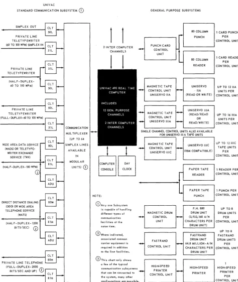
Figure 3-7. UNIVAC 490 Real-Time System - Simplified Block Diagram
UP-3900
UNIVAC 490 SPURT
3SECTION: PAGE:
UNIVAC
STANDARD COMMUNICATION SUBSYSTEM
CD
GENERAL PURPOSE SUBSYSTEMSSIMPLEX OUT
PRIVATE LINE TELETYP EWR!TER (60 TO 100 WPM) SIMPLEX IN
PRIVATE LINE TELETYPEWRITER
(HALF-DUPLEX-60 TO 100 WPM)
PRiVATE LINE TELETYPEWRITER (FULL- DUPLEX-60 TO 100 WPM)
WiDE AREA DATA SERViCE (WADS) OR
TELETYPE-WRITER EXCHANGE SERVICE (TWX)
(HALF-DUPLEX-lOO WPM)
DIRECT DISTANCE DIALING (DDD) OR WIDE AREA TELEPHONE SERVICE
(WATS) (HALF- DUPLEX-1200
BITS/SEC)
CD
PRiVATE LINE TELEPHONE (FULL-DUPLEX-2000 M\
BITS/SEC AND UP)
0
1
1
I~
2 INTER COMPUTER CHANNELS
I
--PUNCH CARD CONTROL
UNiT
MAGNETIC TAPE CONTROL UNIT UNISERVO IIA
MAGNETIC TAPE CONTROL UNIT
UNISERVO lilA
r-~
I
10...
~
80 COLUMN PUNCH
80 COLUMN READER
UNISERVO IIA (READ OR WRITE)
UNISERVO lilA (READ/READ
OR READ/WRITE) COMMUNI CA TION
MUL TIPLEXER (UP TO 64 SIMPLEX LINES
AVAILABLE
SINGLE CHANNEL CONTROL UNITS ALSO AVAILABLE FOR UNISERVO III A TAPE UNITS
!N
MODULAR UNITS)
CD
COMPUTER CONSOLE
NOTE:
DAY CLOCK
CD
An y one Subsy stemis capable of handling
different types of
communi cation
facilities at the
same time.
o
Where indicated,associated common carrier equipment is
required in addition to the line facilities.
0ThiS chart only shows
a few of the typical
communication subsystems
that can be connected to
th e sy stem, many other
configurations are possible
-MAGNETiC TAPE CONTROL UNIT UNISERVO IIIC
MAGNETIC DRUM CONTROL
UNIT
FASTRAND CONTROL UN IT
HIGH-SPEED PRINTER CONTROL UNIT
Figure 3-2. UNIVAC 490 Real-Time System
(Expanded Block Diagram)
-UNISERVO IIIC (IBM COMPATIBLE)
PAPER TAPE READER
PAPER TAPE PUNCH
F.H. 880 DRUM UNIT (3,932,160 A/N CHARACTERS PER
DRUM UNIT)
FASTRAND DRUM UNIT 64.8 MI LLiON - A/N CHARACTERS PER
DRUM UNIT
HIGH-SPEED PRINTER
1 CARD PUNCH PER CONTROL UNIT
1 CARD READER PER CONTROL UNIT
UP TO 12 IIA UNITS PER CONTROL UNIT
UP TO 16 lilA UNITS PER CONTROL UNIT
I
uP TO i2 iiiC TAPE UNITSPER CONTROL UNIT
1 READER PER CONTROL UNIT
1 PUNCH PER CONTROL UNIT
UP TO 8 DRUM UNITS
PER CONTROL UNIT
UP 108
FAST RAND DRUM UNITS
PER CONTROL UNIT
HIGH-SPEED PRINTER
PER CONTROL UNI T
UP-3900
UNIVAC 490 SPURT
4SECTION: PAGE:
4. COMPONENT DESCRIPTION
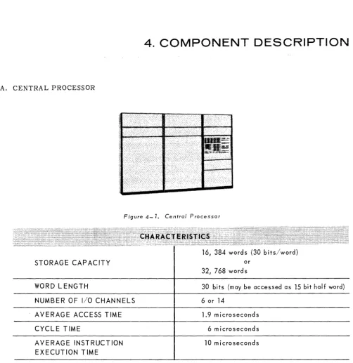
A. CENTRAL PROCESSOR
Figure 4-7. Central Processor
STORAGE CAPACITY
WORD LENGTH
NUMBER OF I/O CHANNELS
AVERAGE ACCESS TIME
CYCLE TIME
AVERAGE INSTRUCTION EXECUTION TIME
16, 384 words (30 bits/word) or
32[ 768 words
30 bits (may be accessed as 15 bit half word)
6 or 14
1.9 microseconds
6 microseconds
10 microseconds
The UNIVAC 490 Real-Time System Central Processor is a binary computer designed for real time and batch processing, for concurrency of operations, for the employment of advanced programming concepts such as those incorporated in the SPURT assembler, the REX executive routine, the various input/output routines; and for the use of extremely extensive and rapid mass random access storage and communications subsystems as well as magnetic tape auxiliary storage, punche d card equipment, and a variety of special peripheral devices.
It employs 62 basic instructions which, by automatic manipulation directed by the contents of the instruction word, can be made to perform practically any desired programming function.
4
SECTION:
2
UNIVAC 490 SPURT
PAGE:
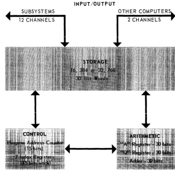
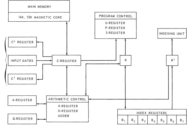
A simplified diagram of the principal elements of the Central Processor is shown in Figure 4~2.
For directness of presentation, only those elements referred to in program instructions are shown.
• Control
SUBSYSTEMS 12 CHANNELS
INPUT /OUTPUT
OTHER COMPUTER 2 CHANNELS
Figure 4-2. Central Processor - Simplified Block Diagram
The control portion of the Central Processor coordinates the flow of data between the arithmetic and storage units. It contains a program address counter which holds the 15 bit address of the next ins truction to be executed throughout the program and seven 15 bit index registers .
• Storage
Storage consists of 16,384 or 32,768 30 bit words. Areas of storage are automatically allocated by the executive routine (REX) according to the requirements of operating programs.
• Arithmetic
The arithmetic unit comprises a 30 bit "A" register, a 30 bit "Q" register and a 30 bit adder.
TIlt:: t~ A" CJ.lld
"Q"
i"~gI5tt:i5 Cire uSed togethel iii wultiplicaticrl arld div'isi~~ ~r:d, 'Cy'l,The:1 de8i!"eci,in 60 bit capacity . .,t\!! arith:r:etic ape~8.tians are perf0!'!!:ed h bi!"!afY fO!'!11. SUb tr8CHol1 i~ per-formed in the end arollnd borrow manner; addition is perper-formed by complementation of the addend and subtraction from the augend.
UP-3900
UNIVAC 490 SPURT
4SECTION: PAGE:
• Input/Output
All input/output data transfers are automatically controlled by signals emanating from the Central Processor or from the peripheral subsystems themselves. Any general purpose input/ output channel can accommodate a UNIVAC 490 Real-Time System peripheral device. All I/O channels are buffered. Each input/output device has associated with it a Control Unit which, once activated by the Central Processor, carries out the entire operation of the instruction given it while the Central processor proceeds with other tasks. This is invaluable. For example, in the case of a simple Print instruction, the Central Processor can, during the execution time -the printing of one line - execute more than 9,000 other instructions. Equally important is the fact that any input/output device can, through its Control Unit, instantly signal the Central Processor if it requires a response to an inquiry or if it has completed a task and is ready to begin another. Through REX, the execu ti ve routine, all activities, both in ternal and external to the Central Processor, are propetly correlated, assigned the necessary areas of storag€, and carried out in the most advantageous sequence.
B. CLOCKS
Processing timelines, an inherent characteristic of real time processing, requires the system to be extremely time conscious. Three precision electronic clocks provide the UNIVAC 490 Real-Time System with unequalled timing sensitivity.
1. Day Clock
A feature particularly suited to real time problems is the 24 hour Day Clock. This electronic clock interrupts the computer with the current time of day expressed in hours (0-23), minutes (0-59) and half minutes (0-1). A visual display of the time as indicated by the Day Clock is located on the operator's cons ole.
The Day Clock can be used to initiate a variety of subroutines at specific times during the day. Error checking routines, trace routines, output conversions, management report pro grams, maintenance routines and memory dumps are some of the many routines which can be initiated by the Day Clock.
2. Real Time Clock
Of particular benefit to statistical analysis of computer utilization, the UNIV AC 490 Real-Time System contains an incremented clock called the Real Time Clock. This clock is a 15 bit register located in computer memory. Approximately once each millisecond the clock is incre-mented by one. Since 15 bits will allow a maximum count of 32,768, this clock will go through a complete cycle in approximately 32 seconds.
This clock can be used for precision timing of compu ter functions such as the elapsed time between the receipt of an inquiry and the transmission of a reply. The compilation of such statistics are an invaluable aid in analyzing and improving computer utilization.
3. Interval Timer
Like the Real Time Clock, the Interval Timer is a 15 bit register in computer storage which is incremented once each millisecond. The major difference between the two clocks is that the Interval Timer provides an unconditional interrupt to the computer upon reaching a full count of 32,768.
4
SECTION: 4
UNIVAC 490 S·PURT
PAGE:
Erroneous input could perhaps cause a routine to initiate a repetitive logical path. The Interval Timer is set when a transaction is initiated. The time of interrupt is slightly in excess of the longest normal transaction. If an interrupt occurs, the real time program is prepared to enter a routine for analysis and possible reinitiation of the transaction which caused the interrupt.
C. SUBSYSTEMS
A subsystem consists of one or more peripheral units of the same type connected to an available input/ output channel. Each subsystem is controlled by a channel synchronizer/control unit that interprets the control signals and instructions issue d by the Central Processor, effects the transfer of data to or from the selected unit and the Central Processor, indicates to the Central Processor the status of the available peripheral units, and informs the Central Processor when errors or faults that affect the operation of the subsystem occur. The Central Processor and the subsystems have capabilities which lead to great efficiency in their mutual operations.
Wh~n the main program requires that the Central Processor employ a subsystem, the Central Processor issues con trol signals which select the proper subsystem and initiate the desired action. Once this is d one the execution of the main program automatically continues until the subsystem has completed the required action. At this point the subsystem signals the Centrai Processor that the action is complete and the Central Processor now deals with the results of the action taken: for example the processing of data transferred from the subsystem.
In similar manner a subsystem signals the Central Processor its state of readiness to require action on the part of the Central Processor, such as response to an inquiry, and it also signals the Central Processor when its requirements have been met. These characteristics not only provide almost instantaneous availability of the services of the subsystems to the Central Processor, and those of the Central Processor to the subsystems, but they also reduce to at most a few thousandths of a second those Central Processor delays ordinarily associated with drum latency periods, magnetic tape reading or writing, or the employment of printing, punched card, or communications systems.
During the execution of input/output instructions the Central Processor proceeds with the main program, taking action on results of the operation only on receipt of a signal from the subsystem indicating that the operation is complete.
UP-3900
UNIVAC 490 SPURT
SECTION:
1.
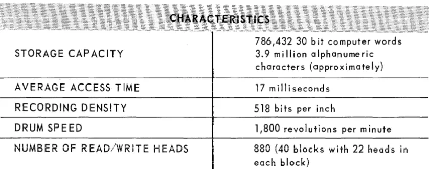
Flying Head~880 Magnetic DrumFigure 4-3. Flying Head-BBO Magnetic Drum Unit
STORAGE CAPACITY
AVERAGE ACCESS TIME
RECORDING DENSITY
DRUM SPEED
NUMBER OF READ/WRITE HEADS
786,432 30 bit computer words 3. 9 mill ion a I ph a n u me ric characters (approximately)
17 milliseconds
518 bits per inch
1,800 revolutions per minute
880 (40 blocks with 22 heads in
each block)
4
The Flying Head~880 Magnetic Drum Subsystem is a large capacity, high speed random access storage device used for program storage, temporary data storage, or file storage. As many as eight Flying Head~880 Magnetic Drum Units may be connected to any available input/ output channel.
The magnetic drum units used in the Flying Head-880 Magnetic Drum Subsystem differ from conventional drum units in that the read/write heads float on a boundary layer of air created by the drum's rotation. Since the boundary is extremely thin, (less than 0.0005 inch) the head to surface distance is reduced and the read/write heads follow the contours of the drum in precise manner. This feature permits a greater recording density since it eliminates the dis~ advantages of the wider head to surface distance required in conventional drum units to compensate for surface irregularities.
PAGE:
The read/write heads are positioned around the drum in 40 groups of 22 heads each. Each head reads from or writes upon a recording track that revolves beneath it.
Each Flying Head-880 Magnetic Drum Unit has 128 6 bit track recording bands, each capable of storing 6,144 30 bit computer words; that is, 786,432 computer words (3.9 million alphanumeric characters) can be stored on a single unit.
4
SECTION:6
UNIVAC 490 SPURT
UP-3900PAGE:
The read/write heads record information on the drum at a density of 518 bits per inch while it is revolving at a speed of 1,800 revolutions per minute. Average access time is 17 milliseconds,
All read operations are parity checked. All search operations may be conducted off line; that is, once the search instruction is received by the drum synchronizer control unit, the Central Processor is free for other functions until the search is completed.
2. FASTRAND* Mass Storage Subsystem
~':!:!.~~ ... '",'''''
~~~
~... « "'''''~'''
""-=--Figure 4-4. FASTRAND Mass Storage Unit
STORAGE CAPACITY
AVERAGE ACCESS TIME
RECORDING DENSITY
DRUM SPEED
NUMB ER OF READ/WRITE HEADS
12,976, 128 30 bit computer words 65 million alphanumeric characters (approxi mate Iy)
92 milliseconds
1,000 bits per inch
870 revolutions per minute
64
The F ASTRAND Mass Storage subsystem is an extremely large capacity random access mass storage device. As many as eight FASTRAND Mass Storage Units may be connected to any availa ble input/output channel.
Each FASTRAND Mass Storage Unit in the subsystem contains two magnetic drums. These drums are similar to those used in the Flying-Head-880 Magnetic Drum Subsystem in that they employ flying read/write heads; however, these drums have an additional feature, the ability laterally to position the read/write heads.
On each drum there are 3,072 recording tracks each of which can store 2,112 30 bit computer words; that is, 6,488,064 computer words can be stored on one drum. Since there are two drums in a F ASTRAND Mass Storage Unit the total storage capacity is 12,976,128 computer words per unit, or approximately 65,000,000 characters. The total words of storage per avail-able channel is approximately 104,000,000; the total characters, 520,000,000.
UP-3900
UNIVAC 490 SPURT
4 SECTION:a. Data Arrangement - Access Time
The data is recorded around the circumference of the drums in tracks. ~ach track WIll
contain 2,112 words. These words are grouped into logical records called Sectors. A sector consists of 33 words.* Therefore, each track contains 64 sectors.
The 64 read/write heads are moun ted on one head positioning bar and all move in unison. Each head will cover 96 tracks. The addressing logic is such that data from track 1 under head 1 is sequentially followed by data from track 1 under head 2 etc., through the entire 64 heads. Thus by one positioning of the heads (which may be accomplished by separate instructions or as part of a read or write instruction) 4096 sectors (135,000 words) are available without further head positioning. This feature when coupled with good systems design and data layout can res ult in reduc ing access time for many references to 35 milliseconds.
Among the valuable features of the F ASTRAND system is a unique search function. The search may be initiated to search on the first word of each sector or it may be initiated to search all words of the sectors in volved. When a find is made, the Search function automatically converts into a read operation as specified by ins truction. In the process of searching the operation may be limited to search through only 64 sectors or to search through 4096 sectors. This variable search length feature is under program control.
All functions of the F ASTRAND are buttered trom the Central Processor so that the computer may continue processing while records are being accessed on the F ASTRAND unit.
All read operations are parity checked.
* Information is recorded on FASTRAND in 33 word sectors. (a word contains 30 bits, five 6 bit characters)
4 8
UNIVAC 490 SPURT
UP-3900SECTION: PAGE:
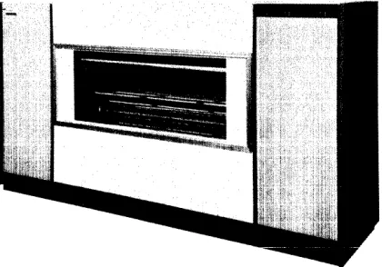
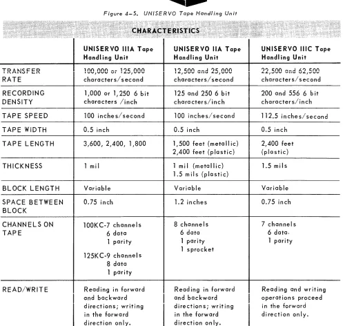
3. UNISERVO* Magnetic Tape Subsystems
Figure 4-5. UN/SERVO Tape Handling Unit
r : : ' . ' . " :, ":::~ ,
'CHARACT,E'RISTICS '
;, ~ .' _oj: --': . :.~ .::. ",; \ ; , . : ':. '. . ' v,'-UNISERVO IliA Tape UNISERVO IIA Tape UNISERVO IIle Tape Handl ing Unit Handling Unit Handling Unit
TO A "-I~ ceo
"',",''1v' L..I'- 1001000 Oi 1251000 121500 and 251000 221500 end 621500
RATE character s/ second characters/ second characters/second
RECORDING 1,000 or 1/250 6 bit 125 and 250 6 bit 200 and 556 6 bit DENSITY characters linch characters/inch character s/i n ch
TAPE SPEED 100 inches/second 100 inches/second 112.5 inches/second
TAPE WIDTH 0.5 inch 0.5 inch 0.5 inch
TAPE LENGTH 3,600, 214001 11800 11500 feet (metallic) 2,400 feet
2AOO
feet (plastic) {plastic}THICKNESS 1 mi I 1 mi I (metallic) 1.5 mils
1.5 mils (plastic)
BLOCK LENGTH Variable Variable Variable
SPACE BETWEEN 0.75 inch 1.2 inches 0.75 inch
BLOCK
CHANNELS ON 100KC-7 channels 8 channels 7 channels
TAPE 6 data 6 data 6 data.
1 pari ty 1 parity 1 parity
125K C-9 channe Is
1 sprocket
8 data 1 parity
READ/WRITE Reading in forward Read ing in forward Reading and writing and backward
I
and backwardI
operat ion s proceed directions; writing directions; writing in the forward in the forward in the forward direction only. direction only. direction only.UP-3900
UNIVAC 490 SPURT
4
SECTIO.N:a. UNISERVO IlIA Tape Handling Unit
',' , .: .. t:./,ciAiiAt.
\~,'iE:RISfi'cs,
.'.
, . : : ~ ~ ~ • • y "., ."h" " ,"' .;.-" , <~u«. " ,,~, <' > ~ " , .~ . ~" >:< '" • ~, ~." ·t· ;
"
TRANSFER RATE
100,000 or 125,000 characters/second
RECORDING DENSITY 1,000 or 1,250 6 Bit characters/inch
TAPE SPEED 100 inches/second
TAP E WIDTH
0.5 inchTAP E LENGTH 3600 I 2400, 1800
THICKNESS 1 mil
BLOCK LENGTH Variable
SPACE BETWEEN BLOCKS 0.75 inch
CHANNELS ON TAP E lOOKCm7 channels
6 data 1 parity
125KC-9 channels 8 data 1 parity
READ/WRITE OPERAT ION R eadi ng in forward and backg ward directions; writing in the forward direction only.
The UNISERVO IlIA Tape Handling Unit is a high speed magnetic tape storage device. The UNISERVO IlIA tape subsystem is connected to the UNIVAC 490 System through any avail~ able general purpose channel. Up to 16 tape units may be connected through one channel control unit. Several subsystems may be connected - one subsystem per channel.
Data is written or read to or from the UNISERVO IlIA Tape Handling Unit at a rate of 100,000 or 125,000 characters per second. The recording is done in the variable blo~k length mode. The UNISERVO IlIA Tape Handling Unit has an automatic read after write feature to provide the maximum assurance that the data has been recorded correctly on the tape. Automatic re-covery, bad spot detection and skipping are provided through a combination of hardware and executive program action.
Among the outstanding functions of the UNISERVO IlIA magnetic tape systems are: Read Forward, Read Backward, Write Forward, Masked Search, and High Speed Rewind.
As in the case of drum storage (of both types) and the other available magnetic tape units, the search function is conducted in the off line manner - that is, the control unit, once given the command by the Central Processor, takes over and the processor proceeds with the execution of other instructions in its program until the desired item is located.
9
4
SECTION:
10
UNIVAC 490 SPURT
PAGE:
The maske d se arch function is extreme ly valuable in that it greatly simplifies pro-gramming because a search can be made upon any portion of an identifier word. The advantages of rapid rewind are obvious.
There are mechanical features of the UNISERVO IlIA Tape Handling Unit which contribute a good deal to its generally recognized status as the most advanced, reliable, and efficient magnetic tape system which now exists. It uses tape only 1 mil thick (mos t other tapes are 1. 5 mils thick). Thus, more tape can be wound on a reel of normal size, and there can be more data per reel. Also, the tape is vacuum clutched which reduces slippage and tape wear and shrinks start/stop time to three milliseconds. Closing of the tape unit door automatically moves a newly mounted tape to its load point, ready for use.
When data is to be stored and manipulated by means of magnetic tape in large quantities and at high speed, UNISERVO IlIA Tape Handling Units provide the world's outstanding system, for the reasons cited above.
b, UNISERVO I1A Tape Handling Unit
TRANSFER RATE
RECORDING DENSITY
TAPE SPEED
TAPE WIDTH
TAPE LENGTH
THICKNESS
BLOCK LENGTH
SPACE BETWEEN BLOCKS
CHANNELS ON TAPE
REA D /W R I TEO P E RA T ION
12,500 and 25,000 characters/ second
125 and 250 6 bit characters/inch
100 i nches/ second
0.5 inch
1,500 feet (metallic) 2,400 feet (plastic)
1 mil {metallic} 1.5 mils {plastic
variable
1.2 inches
8 channel s 6 data
1 parity 1 sprocket
Read i ng in forward and backward directions; writing in the forward direction only.
UP-3900
UNIVAC 490 SPURT
4SECTION:
The UNISERVO IIA Tape Handling Unit is a moderate speed, low cost magnetic tape subsystem which may be connected to the UNIV AC 490 system, via a control unit through any available general purpose channel. Data is written or read to or from UNISERVO IIA units at rates of 12.500 or 25,000 characters per second. The subsystem can also read data from a magnetic tape produced by a UNITYPER
*.
Up to 12 UNISERVO IIA units may be employed through one synchronizer control unit connected to one general purpose channel. As many units as the installation may require may be em ployed by the us e of more than one general purpose channel.
Data may be written or read in either a fixed or variable block length. Fixed length is 720 characters. Variable length is entirely at the discretion of the user of the system. The only restrictions are that one block must comprise at least one computer word, and that it must not be so long as to exceed the system's storage capacity. The UNISERVO IIA Tape Handling Unit as a unit of the UNIVAC 490 System is completely compati-ble with the UNIVAC I, II,
III
computer systems, and the UNIVAC 1103A, 1105 and 1107 systems, as well as the UNIVAC File Computer, the Solid State and STEP systems, without off line tape conversion. Any tape unit on a given channel may communicate with the computer while the other units are rewinding.Both read and search operations may be conducted when the tape is moving either forward or backward. The UNISERVO IIA subsystem can detect and signal end of file.Cend of logically related blocks of data) when reading or searching. As explained under UNISERVO IlIA Unit, search is conducted in the off line manner.
,. Trademark of the Sperry Rand Corporation
11
4
SECTION:
12
UNIVAC 490 SPURT
PAGE:
c. UNISERVO IIIC Tape Handling Unit
TRANSFER RATE 22,500 and 62,500
characters/second
RECORDING DENSITY 200 and 556 6 bit
characters/inch
TAPE SPEED 112.5 inches/second
TAP E WIDTH 0.5 inch
TAPE LENGTH 2,400 feet
(plastic)
THICKNESS 1.5 mils
BLOCK LENGTH Variable
SPACE BETWEEN BLOCKS 0.75 inch
CHANNELS ON TAPE 7 channeis
6 data 1 parity
READ/WRITE OPERAT ION Reading and writing operat ion s proceed in the forward direction only.
The outstanding virtue of the UNISERVO IIIC subsystem is that it provides compatibility between the magnetic tapes of the world's two greatest producers of computer systems -The Univac Division of the Sperry Rand Corporation and IBM. -There are many instances in which analysis shows that a UNIVAC computer such as the 490 is preferable to a marked degree, but the data to be processed is already on other than UNIVAC tapes. The UNISERVO IIIC Tape Handling Unit is the answer. When this subsystem is employed, offline conversion is utterly unnecessary. You simply take the old tapes, put them on the new machine, and go from there. The programming problems are insignificant because the circuitry of the UNISERVO IIIC Tape Subsystem control unit automatically deals with them.*
Up to 12 UNISERVO IIIC units may be connected to any available general purpose channel and, as with the other subsystems, more than one channel may be used for this purpose.
Data may be recorded at 200 or 556 characters per inch. The read/write speed is 22,500 or 62,500 characters per second. A tape may contain more than 3000 blocks of 1000 words each in high density binary recunEng, ur 1000 u10~h.8 0f 1000 wVlds each ill Ie .. ·; dcn~ity.
Block length, subject only to storage capacity, is completely variable. For practical pur-poses, this is to say that it is completely at the will of the systems analyst or programmer.
UP-3900
UP-3900
UNIVAC 490 SPURT
4SECTION: PAGE:
The UN ISERVO I1IC has the further advantage that, unlike many earlier devices of its kind, it can write data on tape in what is known as the non stop mode. This means that block after block of data may be written wi thout re-initiating the write instruction. The
resultant simplification of programming is significant" As explained under UNISERVO IlIA
Unit search is conducted in the offline manner.
4.
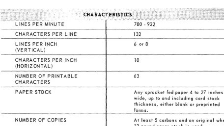
High-Speed Printer SubsystemFigure 4-6. High=Speed Printer
LINES PER MINUTE
CHARACTERS PER liNE
liNES PER INCH (VE RT ICAl)
CHARACTERS PER INCH (HORIZ ONTAl)
NUMBER OF PRINTABLE CHARACTERS
PAPER STOCK
NUMBER OF COPIES
700 - 922
132
6 or 8
10
63
Any sprocket fed paper
4
to27
inches wid e , up to and inc Iud i n g car d s to c k thickness, either blank or preprinted form s.At least 5 carbons and an original when
12 pound paper stock is used.
A High-Speed Printer subsystem may be connected to any available general purpose channel. Operating under program control, the subsystem produces single or multiple copy data at a rate of 700 lines of alphanumeric characters per minute, up to 922 lines of numeric characters per minute. The printed lrne may be up to 132 characters iong.
4 SECTION:
14
UNIVAC 490 SPURT
PAGE:
Including the blank, or space, the standard character set provides 64 characters: the 26 letters of the alphabet, the digits 0 through 9: seven punctuation marks: comma, period, apostrophe, colon, semicolon, question mark, and exclamation point: and 20 special symbols [] right and left brackets,
0
right and left parenthesis, \ / right and left solidus, &,#,
@,
*,
$,%,
fl, tt, =,<, >,
- (to represent either minus or dash), + and
±.
This is the standard character set.
Other character sets are available on special order to meet special needs.
The printer is designed to prevent a build up of static electricity, facilitating the proper stacking of paper which may be fed directly from the shipping container. Numbered calibrations on the printer enable the operator to record the positioning of a particular form and, at a later time, to set the same type of form to the necessary position. Fine adjustments are provided so that the operator may shift the paper horizontally or vertically the space of one character or line, or less, in either direction. The adjustment may be made while the printer is operating or while it it in the standby condition.
S. Card Subsystems
CARDS PER MINUTE
NUMBER OF OUTPUT STACKERS
l
I
-...J
Figure 4-7. Card Reader and Punch Verifier
CARD READER
600
3
PUNCH VERIFIER
150
2
UP-3900
UNIVAC 490 SPURT
4SECTION: PAGE:
The Card Reader reads and checks 80 column cards at the rate of 600 cards per minute. Under direction of the program, cards are moved from the inpu t hopper in to the card channel and pass through two read stations. At the first read station the card image is read and stored. At the se-cond read station the card is read again and compared to the image that was stored. If the compa-rison is equal, the data on the card is transferred to the Central Processor, and the card goes to the normal output stacker or the stacker by the program.
The Punch Verifier punches and checks 80 column cards at the rate of 150 cards per minute. Under direction of the program, a card is sent through the unit, information generated by the pro-gram is punched into the card at the punch station, the card is moved to the wait station, a!\d then is moved to the third read station where it is verified. The verification is accomplished by reading the card and comparing the results hole by hole with the card image which is retained in the control unit until the checking is complete. When this has been completed the card is placed in the normal output stacker or the stacker selected by the program.
Translation from card code to internal machine code and vice versa is automa tically accomplished within the control unit through the use of core storage and table look up techniques. By changing the contents of the table nonstandard translations may be performed.
6. UNIVAC Standard Communication Subsystem
The UNIVAC Standard Communication Subsystem enables the UNIVAC 490 Real-Time System to receive and transmit data via any common carrier in any of the standard codes and at any of the standard rates of transmission up to 4800 bits per second. It is the only communication system which can receive data from or transmit data to low speed, medium speed, or high speed lines in any com bina tion.
The subsystem consists of two principal elements, the Communication Line Terminals (CL T's), which make direct connection with the communication facilities, and the Communication Multi-plexer through which the CL T's deliver data to and receive data from the Central Processor. A Communicaiton Multiplexer may be connected to any general purpose computer channel or two or more multiplexers may be connected to two or more channels. If required, a number of multiplexers may be connected through a Scanner Selector to the same general purpose channel. The total number of multiplexers which can be connected to a general purpose channel is dependent on the number and speed of the communication systems linked to the multiplexers by their CL T's.
a. Communication Line Terminals (CL T's)
There are three basic kinds of input and output CL T's: low speed (up to 300 bps*), medium speed (up to 1600 bps) and high speed (2000 - 4800 bps). Each is easily adjusted to the speed and other characteristics of the type of line with which it is to operate - see CHARACTERIS-TICS at the beginning of this section. Each CL T requires one position, either input or output, of the Comm unicstion Multiplexer.
The CL T - Dialing is an output CL T which is employed to enable the Central Processor automatically to establish comm unications wi th remote points via the common carrier's switch-ing network. Each CL T - Dialswitch-ing requires one output position of a Communication Multiplexer.
Since CL T - Dialing does not transm it da ta, it is always used in conjunction with an output CL T, an input CL T, or, for two way communications, both.
* bits per second
4
SECTION: PAGE: 16
UNIVAC 490 SPURT
b. Comm unica tion Multiplexe r
The Communication Multiplexer functions as the link between the processor and the CLT's and is available in modules to handle 4,8, 16,32, or 64 CLT's. In each of these modules, an equal number of input and output CL T positions are provided. For example a 64 position Communication Multiplexer can accommodate up to 32 input and up to 32 output CLT's.
The CLT's may request access to the Central Processor via the Communication Multi-plexer in random sequence, or severa 1; or conceivably; all CLT's might request access Simultaneously. The Communication Multiplexer automatically assigns priorities among CL T's requesting access and identifies to the Central Processor the particular CLT granted access.
COMMUNICATION MUL TiPLEX'ER
UP TO 64 CL T·S
COMMUNICATION MUL T!PLEXER
UP TO 64 CL T·S
Figure 4-8. One Communication Multiplexer per General Purpose Channel
UNIVAC 490
SCANNER SELECTOR
COMMUNICATION MUL TIPLEXER
UP TO 64 CL T'S
COMMUNICATION MUL TIPLEXER
UP TO 64 CL T'S
Figure 4-9. Multiple Communication Multiplexers per General Purpose Channel using Scanner Selector
UP-3900
UNIVAC 490 SPURT
4SECTION: PAGE:
CHARACTERISTICS
INPUT COMMUNICATION LINE TERMINALS (CL T'5)
LOV{ SPEED
T
rv'EDlurv1 SPEEDI
HIGH-SPEEDNAME CL T51L CL T81L CL T81M CL T81P CL T81H
CODE 5 LEVEL
6,1,
or8
LEVEL5,6,1,or
8 LEVEL I 8 LEVEL5,6,I,or8
LEVEL*ASYNCHRONOUS ASYNCHRONOUS ASYNCHRONOUS ***TIMING SIGNAL **SYNCHRONOUS MODE
BIT SERIAL BIT SERIAL BIT SERIAL BIT PARALLEL BIT SERIAL
I
UP TO 1600 bpsI I
SPEED UP TO 300 bps UP TO 300 bps
I
UP TO 75 cpsI
2000-4800 bpsOUTPUT COMMUNICATION LINE TERMINALS (CL T'5)
LOW SPEE 0 MEDIUM SPEED HIGH-SPEED t DIALING
NAME CL T50L CL T80L CL TSOM CL T80P CL T80H CL T DIALING
CODE 5 LEVEL 6,7,or8 LEVEL 5,6.7, or 8 LEVEL 8 LEVEL 5,6,7, or 8 LEVEL 4 LEVEL I
ASYN CH RONOUS I I i
I ASYNCHRONOUS ASYNCHRONOUS TIMING SIGNAL SYN CH RONOUS I TIMING SIGNAL I I
I
MODE
BIT SERIAL BIT SERIAL BIT SERIAL BIT PARALLEL BIT SERIAL BIT PARALLEL !
i I I
I
SPEED UP TO 300 bpsi
UP TO 300 bps UP TO 1600 bpsI
UP TO 75 cpsI
I 2000-4800 bps I VARIABLECOMMUNICATION MUL TIPL EXER
NAME FUN CTION
C/M-4 Connects 2 input and 2 output CL T's to General Purpose Channel
C/M-8 Connects 4 input and 4 output CL T's to General Purpose Channel
C/M-16 Connects 8 input and 8 output CL T's to General Purpose Channel
C/M-32 Connects 16 input and 16 output CL T's to General Purpose Channel
C/M-64 Connects 32 input and 32 output CL T's to General Purpose Channel
Types
of
Communication Service provided:PRIVATE LINE TELETYPEWRITER WIDE AREA TELEPHONE SERVICE (WATS) PRIVATE LINE TELEPHONE
WIDE AREA DATA SERVICE (WADS)
TELETYPEWRITER EXCHANGE SERVICE (TWX) DIRECT DISTANCE DIALING (DDD)
t CLT-DiaIing - This is an output CLT employed when the Central Processor is automatically to establish communications with remote points via the common carrier's switching network.
* ASYNCHRONOUS - Employs start and stop bit with each character to establish timing.
* * SYNCHRONOUS - Uses timing characters at pre-determined intervals between data charac ters.
*** TIMING SIGNAL - Indicates the presence of a character at a Data Set.
I I
I
I
I
4 SECTION:
18
UNIVAC 490 SPURT
PAGE:
7. Punched Paper Tape Subsystem
a. Paper Tape Reader
"n ,.. • ~'"i"" wo, w .;~,.';; <:;:,: ,
,
~~:,~"1fi#~'~¥'~~~:~'~i~:~.~':.!
READING RA TENUMBER OF CHANNELS
CHARACTERS PER !NCH
TAPE SPEED
TAPE WIDTHS
b. Paper Tape Punch
PUNCH ING RATE
NUMBE R OF CH ANNELS
CHARACTERS PER INCH
TAPE SPEED
TAPE WIDTHS
,: .. '", :~ t' "'
;¢ffA·IA)CTS1R.'S~I;bi}.
, ," ";, ::: .q _", ... "<; A~.,:~:,
400 characters/second
5, 6, 7,
or 810
40 i nche s/ second, free runn i ng (forward or reverse)
11/16,7/8, or 1 inch
110 characters/second
5,6,7, or 8 plus in line sprocket.
10
11 inches/second
11 /16, 7/8 , or 1 inc h
The Punched Paper Tape Subsystem enables the UNIVAC 490 Real-Time System to read or punch paper tape in all standard codes with programmed translation. A paper tape sub-system may be connected to any available input/output channel. Parity checking may be preformed in either reading from tape or in punching, under control of the Central Pro-cessor Program. The subsys tern handles 5, 6, 7, or 8 channel tapes at a readin g rate of 400 characters per second and at a punching rate of 110 characters per second.
Tape may be read, or punched, employing spools or individual unspooled strips of tape. When des ired, num bers 0 f s trips can be spliced together and s pooled for reading. When
spools of tape are used as input to the reader, a supply reel and a take up reel are employed. Tape is read in a forward direction and may be back spaced a specified num-ber of characters under program control.
UP-3900
UNIVAC 490 SPURT
5-A
SECT-ION: PAGE:
5. PROGRAMMING IN SPURT
A. COMPUTER ELEMENTS RELATED TO PROGRAMMING
1. The Computer Word
The most fundamental level of storage in the computer is the internal data word. A data word is made up of 30 binary bit positions as shown in Figure 5-1. Each of these bit positions may represent a value of 0 or 1. When used for arithmetic operations, a value of 1 in bit position 29 will indicate a negative quantity; a value of 0 indicates that the value represented by the remaining bit positions is positive.
MOST
SIGNIFICANT BIT
SIGN BIT
Figure 5-7. Basic Internal Data Word
LEAST SIGNIFICANT BIT
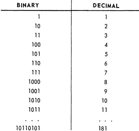
Values may be expressed in binary notation for which the base is 2 instead of 10. The following equivalence exists:
BINARY
DECIMAL
1
10
2
11
3100
4
101
5
110
6111
7
1000
8
1001
91010
10
1011
1110110101
1815-A
SECTION: PAGE:
2
UNIVAC 490 SPURT
The use of binary digits to represent large values is cumbersome. The use of octal notation for which the base is 8 is used for convenience. The followi ng equivalence exists:
BINARY
OCTAL
1
10
2
11
3
100 4
101 5
110 6
"111
7
1000 10
111111
77
1100101 145
Binary values may be converted to octal notation by starting from the least significan t (rightmost) digit. Each group of three binary digits is expressed as a digit from 0 to 7. By this method:
100 101
' - . ; - ' ' - . ; - ' 145 (octa I)
111 101 000 750 (octal)
' - v - ' - - . - ' - . ; - '
A computer word containing 30 binary bits could be expressed in octal notation as:
7 7 7 7 7 7 7 7 7
Negative numbers are represented as the complement of positive numbers. A value of -3 is represented as:
7 7 7 7 7 777 7 4
The SPURT Assembly System will permit the user to express values as decimal numbers. These will be converted to their binary equi valen ts by the assembler. In order to
distinguish between binary, octal, and decimal numbers, the following subscripting will be used in this manual:
, . _ __ I _ r
n
2 = Dlnury VUIU~ OJ n
n8 = octal value of n
n = decimal value (no subscript)
UP-3900
UNIVAC 490 SPURT
5-A SECTION:Examples:
11
=9
. 8 .
63
= 778When the contents of a computer word are displayed, or if reference is made to a computer instruction word, octal notation will be assumed.
2. Addressing
Each word within the computer has a unique address. The available addresses in
memory may range from 00000 to 377778 (if memory capacity is 16,384 words), or from 00000 to 777778 (if memory capacity is 32,768 words).
a. Data Addressing
Data is addressed by instructions that are themselves contained in the memory of the computer. When it is required to acces s data to complete an instruction, the instruction will contain an address portion capable of containing a maximum value of 777778,
b. Instruction Addressing
A basic computer instruction may be contained within one computer word. Instructions are accessed in memory, analyzed by the computer and then executed.
The next instruction is then accessed at the next sequential location unless a new sequence is specified.
c. Standard Locations
PAGE:
Memory locations 000008 through 001368 have special uses which will be fully explained in the a pp ropdate con text.
3. The Computer Instruction
A description of the basic computer instruction word and a summary of the numeric codes used to initiate computer functions are included in APPENDIX A. These instructions are made available as a reference for checking output from the SPURT Assembler. The SPURT
Assembler provides a more convenient, easily remembered. format for program coding. However, a general explanation of the basic instruction word will clarify such operations as address modification, operand modification, and jump interpretation. Reference will be made to these operations in the text dealing wi th the SPU RT instructions.
The format of the basic computer instruction word is shown in figure 5-2.
129
f
24123
2J20
k
J7
b
J4
y
aI
Figure 5·2. Instruction Word
5-A 4
SECTION: PAGE:
y
J
k
b
UNIVAC 490 SPURT
The value contained in these six bit positions determines the basic operation to be performed. The value is coded as two octal digits. For example, the code 20 specifies an addition of values.
This portion of the word may be a value representing the address of a 30 bit memory location at which the operand used in this operation may be found, or the IS-bit positions of this portion of the word may be the operand used by the instruction.
UP-3900
The most common use of the j portion of the instruction word is to specify a jump condition. If the condition (such as a negative sign and a value of zero in an arithmetic register) is present the next instruction will be skipped. This will permit the user to control program sequence based upon the results of an operation. For those instructions that do not have jump conditions, this portion of the instruction word may have other uses.
The k portion of the word will determine the size and format of the operand used by the instruction. Changes in the k portion will specify an operand which is in the upper 15-bit positions of a data word, the lower IS-15-bit positions, the entire 3D-15-bit positions of a
word with or without additional modification, or the lower portion of the instruction word itself.
The b portion of the instruction contains a value from 0 to ,. It refers to a B-register with a capacity of IS-bit positions that may be used for the non-destructive modification of the y portion of an instruction. For example, if the b portion of an instruction contains a value of 2, the contents of B-register number 2 will be used to modify the instruction.