VIP Implementation for Mil-Std Manchester
Encoder- Decoder Using System Verilog
Nisha G R
1, Aswathy Krishnan
2Scientist/Engineer, SF, QDAC/QRAG/SR/ VSSC, Trivandrum, Kerala, India 1
PG Student [Applied Electronics], Dept. of ECE, MG University College of Engineering, Thodupuzha, Kerala, India2
ABSTRACT: This paper describes the implementation of Verification Intellectual Property(VIP) for MIL-STD- 1553 Manchester Encoder-Decoder logic, using SystemVerilog HDL. VIP is implemented with in-built features like error checking mechanisms, test bench generation as well as appropriate routines to create bus functional models to verify the HDL design code as part of V&V activity. It is designed by generating proper verification plan with directed and error test cases. Coverage Driven Verification technology is adopted here to measure the efficiency of VIP. Functional coverage, code coverage and System Verilog Assertions (SVA) are analysed here. The VIP efficiency is ensured and verified here by 100% code coverage and functional coverage analyses. Simulations, SVA and coverage driven analyses are done using Questa Sim EDA tool and described here as results.
KEYWORDS: VIP , Manchester encoder ,Decoder ,SystemVerilog Assertions (SVA) ,SystemVerilog, Code Coverage, Functional Coverage.
I.INTRODUCTION
The VIP is a verification model which helps the designers and verification engineersfor the validation of their design's functionality. It can be used in most of the simulation based verifications. VIP composed of functional coverage blocks, traffic generators, protocol monitors and bus functional models. Each VIP Comprises the correct routines to create a bus functional models or protocols and also necessary frame work for the test bench generation and checking. Commercially available VIP will give improved time -to -market and reduce risk for the IP dealers and also for the customers. With the interface specification, one can check or verify the complaints by using protocol monitors and checkers. A customer can check or verify system level function and validate target performance by initiating application specific traffic. It can easily connect or mingled with other tools. VIP includes with coverage engine, which recognize the corner cases and test fullness.
VIP implementations of Manchester encoder-decoder are available but VIP is created in first time for Mil-Std Manchester. Previously VIP has been created for RS 232 and UART. Mardav Wala et al [1] proposed integrating and verifying intellectual property blocks using platform express and model Sim. Platform based design is a proven method for minimizing the time and risks involved in designing and verifying a SOC. But it is not possible to use a hardware simulator for checking functional correctness of the component. This paper describes a coverage driven analysis and assertion based verification method for VIP efficiency measurement. This is a new method created especially for Mil-Std Manchester.
Here, VHDL implementation of HD 15530 [2] Manchester Encoder-Decoder digital logic is used as DUT for implementing the VIP. This Encoder-Decoder design logic is divided into encoder unit and decoder unit. Most of the requirements of mil std 1553 is met by this circuit. Encoder produces the sync pulse with parity bit as well as the encoded data bits. The decoder recognizes the valid sync as well as decoding the data bits with parity.
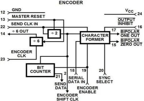
II. ENCODER OPERATION
high on SYNC SELECT input will produce a command sync or a low will actuates data sync. When the Encoder is ready to receive the data, At that time SEND DATA output will go high and it remain high for sixteen ENCODER SHIFT CLOCK periods. Data clocked into serial data input with the every high-to-low transition of the ENCODER SHIFT CLOCK .So the data can be sampled on the low to- high transition of the ENCODER SHIFT CLOCK. The sync bit and Manchester II encoded data are transmitted through the BIPOLAR ZERO and BIPOLAR ONE outputs. The additional parity bit is added with the encoded signal.
Fig 1. Block Diagram of Encoder
If ENCODER ENABLE is continuously high, it encoded the parallel data without any gap. If ENCODER ENABLE must go low, it prevents a consecutive word from being encoded. To discard the Encoder transmission, must be applied a positive signal at MASTER RESET. A low-to-high transition on SEND CLOCK will initializes the Encoder for a new word.
III. DECODER OPERATION
The Decoder requires a single clock with a frequency of 12 times the desired data rate applied at the DECODER CLOCK input. The Manchester II coded data is represented in two ways. The BIPOLAR ONE and BIPOLAR ZERO inputs will receive data from a comparator sensed transformer as specified in Military Spec of 1553. The UNIPOLAR DATA input will accept non-inverted Manchester coded data. The Decoder is continuously monitors the data input lines for a valid sync character. When a valid sync is identified, the valid sync is indicated on COMMAND or DATA SYNC output. When the output is high, valid sync recognize the command and output remain high for sixteen DECODER SHIFT CLOCK periods, otherwise it will generate data word for low sync condition.
. Fig 3. Decoder block diagram
The TAKE DATA output will go high and Decoded data will transmitting through SERIAL DATA OUT in NRZ format. Decoded bits can be shifted on every low to high transition of DECODER SHIFT CLOCK. It may adjust until the TAKE DATA go high. After all sixteen decoded data bits has been transmitted the data is checked for odd parity. A VALID WORD output will indicates the successful reception of decoded data without any parity errors. During the low to high transition of DECODER CLK will abort the decoder transmission.
IV. FUNCTIONAL SIMULATION
IV.A VERIFICATION PLAN
This is generated by going through the design requirements and specifications. Plan express distinct or separate testing procedure by borrowing reserved and unique test cases and by which functionality of the design ensured. Also bringing out bugs in the code if any. Both directed and error test cases are derived here. Some of the Test cases for encoder and decoder are given below.
IV .B SAMPLE TEST CASES-ENCODER
Case1: Encoder reset
All outputs at known state w.r.to releasing edge of “reset”
Case2: Parallel to Serial Encoder Operation
Initiate with Encoder enable
Cycle last for 20µs or one word length
Select valid sync bit. High to low indicates the command and low to high indicates Data word.
Sync bit last for 3µs
16 bit serial data input will send at every high to low transition of encoder clock ( 16 µs)
Encoded datas are serial out with parity through - "Bipolar one& Bipolar zero"
Random data words are checked for ‘N’ cycles.
IV .C SAMPLE TEST CASES-DECODER
Case1: Decoder reset
All outputs at known state w.r.to releasing edge of “reset”
Case2: Serial to parallel Decoder operation
Serial 16-bit data input accept from the MIL-STD 1553 bus
Select valid sync bit. High to low indicates the command and low to high indicates Data word.
Take Data output will go high.
16 bit Decoded dataParallel out with odd parity through "Serial _data out"
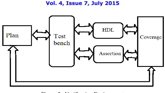
IV .D VERIFICATION ENVIRONMENT
The verification environment is managed with Questa Sim Simulator, ver.10.0, test bench and SVA in System Verilog HDL and DUT in VHDL. A separate assertion files in system verilog are bind with the corresponding test benches to validate design specifications and requirements SystemVerilog Assertions (SVA) are basically a "statement of fact" made by verification engineer[3]. Assertions can verify local to complex conditions in our design. It not only locate bugs but also help to find total covered design logic. And so it acts as the functional checker for entire DUT operations. Functional simulations are also checked with the help of waveform window extensively.
Figure 5. Verification Environment
The whole system specification has been checked by using SVA. Any of the specification has been violated, one can see the failure message in assertion window
.
IV .E TEST BENCH FOR SIMULATIONS
The term “test bench" specifies the stimulus were used to initiate a predestined input sequence for the design and to examine its response. The test bench describes the stimulus for the DUT along with its response for the outputs. Here, the test bench is written in SystemVerilog with predetermined input sequence and they may be included with external data files. The main task of the test bench is that to verify what input patterns to provide to the design and what is the expected throughput of a properly working design.
V .COVERAGE DRIVEN ANALYSIS
V .A CODE COVERAGE
Code coverage is a verification technology is used to recognize what code has been executed. It has to be checked only after the simulation part. If the design may look like a good design but the problem is that it can contain an unknown bugs. It is hardly possible to know the verification is functionally correct, with cent percent certainty and all of the test bench simulate favourably or successfully. The main objective of the code coverage is to find out which code has to forget to exercise in the design. If the test bench was not exactly executed, it should be returned in the design. So, code coverage technology is used for the cent percentage certainty.
It can be classified into four categories. They are Statement coverage, Path coverage, Expression coverage and FSM coverage.
Statement coverage: It is also known as Block coverage, where the block is series of statements. If a single statement is executed, all of the statements in the block will be executed. By the verification suite, it measures how much of the total line of code were executed. Figure 6 shows the analysis window for the statement coverage verification. It will be generated after the simulation part. The tick () mark indicates that statement code which include in the DUT are functionally correct. If shows (x) mark ,indicate that design is functionally incorrect. It will quickly identify and we can browse which statements that were not executed.
Fig .6 statement coverage window of encoder
Conditional coverage: It will be recognize where conditional code was missed in the design. The below diagram indicates, the conditional code coverage of encoder section and which is included in the design was functionally correct.
Fig .7 conditional coverage window of encoder
Path coverage : There is lot of ways to execute a sequence of statements. It is used to measure all of the possible ways ,you can execute the statements . The no. of possible path increases with control statements.
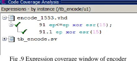
Expression coverage: It measures the various ways of decisions that present in design. The analysis shows the expression coverage of encoder section.
Fig .9 Expression coverage window of encoder
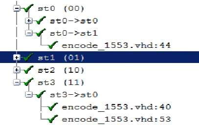
FSM : It is usually, coded using a choice in a case statement, unvisited state clearly identified with uncovered statements. During the verification time it clearly or correctly identifies the state transitions. Figure 9 shows the bubble diagram for FSM. It indicates that state transitions of decoder sections.
Fig .10 FSM coverage window of decoder
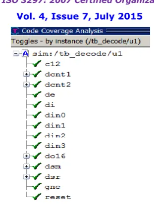
Branch and Toggle coverage : A signal is considered to have fully toggled when it has experienced at least one rising edge and at least one falling edge during the simulation .Figure Shows these coverage windows , which indicates that all the branch and toggles present in the design of encoder -decoder logic was functionally correct
Fig .12 Toggle coverage window of Decoder
V .B FUNCTIONAL COVERAGE APPROACH
Functional coverage measures how much of the original design specification has been exercised by the test bench through simulation. It is concerned with implemented function. The individual scalar value or expression of a sample is known as coverage point. The main purpose of the coverage point is to ensure the important value have been noticed in the sampled value. It can be categorized into two; they are cross coverage and Transition coverage. Cross coverage measures the possible occurrence of the combinational of values. Whereas the transition coverage is manually specified from the implementation. The correctness of the design and the verification completeness can be verified through a true independent path which is provided by transition coverage.
State transition can be specified by using transition coverage. Example 1 specifying the transitions for the cover point.
covergroup CoverPort; coverpoint port
{
bins t1 = (0 => 1), (0 => 2), (0 => 3); }
endgroup
Example .1 Transitions for a cover point
Transaction tr;
covergroup Covecnt1; ecnt2: coverpoint tr.ecnt2; ecnt1: coverpoint tr.ecnt1; cross ecnt1, ecnt2; endgroup
Example .2 sample for cross coverage
5. C ASSERTION BASED VERIFICATION
The specifications of Manchester encoder and decoder section is verified with concurrent assertion properties. The concurrent assertion may specify the behaviour of the design by using statements. Example 3 describes the sample assertion property for the Manchester encoder. The main specification requirements for this property is ,to ensure the 5 clock width of serial data out (eo0 and eo1) as well as encoder enable should be low.
property eleven_ee;
@(posedge c12) disable iff (!reset) (ee==0)|=> ##5 (eo0 | | eo1) ; endproperty
assert property(eleven_ee) else
$error("The eleven_ee fails");
Example 3. Encoder assertion property
Assertion Property expressions can be specified with an implication operator, either |-> or |=>.When the specified condition with "disable iff" is incorrect, the assertion does not work. The example 3 shows that if the reset become true at the positive edge of the clock during the evaluation of the sequence as well as the encoder disable condition .That means when the enable is low ,preceding 5 clock width of serial data out (eo0 or eo1) are high and ensured the required specification. When the negative edge of the clock, the required specification is not ensured and it will never evaluate to true and generates the failure count.
Figure.13(b)Assertions- pass Report of encoder
Table.1, shows the different assertion properties of encoder logic. This is used for the verification purpose.
ASSERTION DESCRIPTION REMARKS
four_eo0 property four_eo0;
@(negedge c12) disable iff (reset) !reset|=> eo0=={(1'b1)};
endproperty
assert property(four_eo0)
else $error("The reset_eo0 fails")
Reset condition
six_esm property six_esm;
@(posedge c12) disable iff (!reset)(esm==2'b01 && ecnt2==4'h0&& ecnt1==4'h5) |=> eo1=={(1'b1)};
endproperty
assert property(six_esm)
else $error("The six_esm fails")
Encoder output condition
nine_esm property nine_esm;
@(posedge c12) disable iff (!reset)
( ecnt1==4'h0 && esm==2'b11 ) |=>ecnt2=={(4'h0);
endproperty
assert property(nine_esm)
else $error("The nine_esm fails")
counter2 condition
Table.1 Assertion - encoder
Specification: Signal ‘gne’ will be active high, if dcnt1=0000h & dcnt2=0001h and becomes active low after 12 more clk cycles.
property nine_de_gne ;
@(posedge c12) disable iff (!reset) (dcnt2==4'h1 && dcnt1==4'h0) |=> ##1 gne ##12 !gne ;
endproperty
assert property(nine_de_gne)
else $error("The de__gne width fails")
Example 3. Decoder assertion property
The property describes that if the reset become true at the positive edge of the clock during the evaluation of the sequence, 12 clk width of 'gne' is ensured. The error case of this specification is ensured by asserting with negedge whether the property on this specification is valid or not and it is ensured by the failure count.
Figure.14(a) Decoder Assertions- Hit/Miss
Table.2 shows some of the different assertion properties excised on Decoder logic. This is used for the verification purpose.
ASSERTION DESCRIPTION REMARKS
one_din1 property one_din1;
@(posedge c12) disable iff (reset) !reset|=> din1=={(1'b0)};
endproperty
assert property(one_din1)
else $error("The reset_din1 fails")
Reset condition
seven_do16 property seven_do16;
@(posedge c12) disable iff (!reset) (de==1)|=> {(do16 == dsr)};
assert property(seven_do16)
else $error("The de_do16 fails")
Output condition
eight_de property eight_de;
@(posedge c12) disable iff (!reset)
(dsm==2'b00 && dcnt2==4'h1&& dcnt1==4'h0) |=> de ##1 !de;
endproperty
assert property(eight_de)
else $error("The de_dcnt1 fails")
State machine condition--1 clk width of 'de' is ensure
Table.2 Assertion- Decoder
VI .SIMULATION RESULTS
The SystemVerilog simulation is performed to verify the DUT of MIL-STD Manchester encoder decoder logic design by using the VIP implemented in System Verilog. Functional integrity of DUT is checked by using Assertions and cover groups along with necessary test inputs.
Here, six types of simulation results are reported.
Encoder with assertion (Miss)
Encoder with assertion (hit)
Decoder with assertion (Miss)
Decoder with assertion (Hit)
Code coverage-100%
As shown in the figure .15(a), 15(b), the encoder and decoder with assertion fails (missed Cases). The red arrow indicates the points where the assertion property has failed. Thus, we can easily check where the specification or general requirements are missed or failed property, using the waveform.
Fig 15 (a) Encoder - Assertion (Miss)
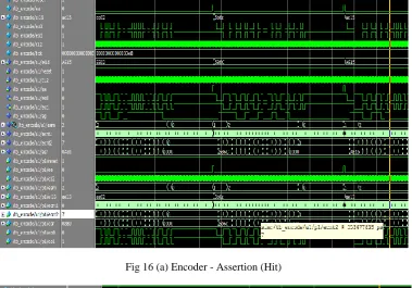
Fig 16 (a) & (b) shows Encoder and Decoder with the assertion (hit). One can see that all the properties are hit and simulated successfully
.
Fig 16 (a) Encoder - Assertion (Hit)
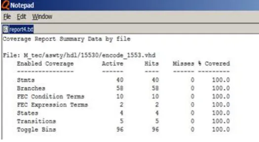
As shown in the figure. 17 (a,b) ,the total coverage of the verified sections. The verified sections are functionally correct and all the assertions and codes were covered.
Fig 17 (a) encoder code coverage
Fig 17(b)Decoder code coverage
Functional coverage is measured by using coverage group. Coverage group is defined in the test bench module. Coverage group encompasses the cover points, arguments .It contains one or more cover points, all these data points are sampled at same time.
covergroup Covecnt1; coverpoint tr.ecnt1 {
bins zero = {0};
bins lo = {[1:3], 5}; bins hi[] = {[8:$]}; bins misc = default; }
endgroup
VII. CONCLUSION
In this paper, the implementation of verification intellectual property for MIL-STD Manchester encoder-decoder described VIP is implemented by adopting verification technologies like code coverage, functional coverage and Assertions using SystemVerilog and Questa Sim EDA tool. The entire logic of Manchester Encoder-Decoder is verified by doing coverage analyses. The efficiency of VIP is measured by 100% code coverage and functional coverage on the DUT. As it is attained the cent percentage on its coverage, the implemented VIP is selected to verify IP of 15530 Manchester encoder-decoder logic used in Indian space programs.
REFERENCES
[1] Mardav Wala ,”Integrating and verifying Intellectual property blocks using platform express and Model Sim ,Circuits and Systems , 48th
Midwest symposium ,pp 758-761 ,2005. [2]Data sheet on HD-15530
[3] Clifford E. Cummings "SystemVerilog Assertions Design Tricks and SVA Bind Files" SNUG Sanjose , pp 5-42 ,2006 [4]Stuart Sutherland, Simon Davidmann .System Verilog For Design, Springer, 2nd Edition ,pp137-166, 2006
[5] Chris Pear , System Verilog For Verification , Springer,2nd Edition,pp.295-302 ,2008
[6]Janic Begeron, Synopsys, Inc. Writing Test benches using System Verilog , Springer , pp.38-46 ,2006 [7]Donmills, System Verilog assertion for design engineers , SNUG Sanjose ,2006
[8] Questa Sim 10.0 User Manual
BIOGRAPHY
.
Nisha G .R ,done the graduation in Bachelor of Engineering in Electronics and Communication Engineering from Bharathiyar University in 1996 ,Tamil Nadu .Joined in VSSC of ISRO in 1997 and acquired 17 years of working experience in the field of design and development of onboard avionics digital systems. Also having the experience in the field of testing and characterization of complex and sophisticated VLSI components like On board FPGA and ASIC designs, Microprocessors ,Microcontrollers ,Memory Devices etc as part of quality assurance programs