A Three-Phase Four-Switch PWM Voltage-Source
Rectifier usingd-q control fed induction motor
drive
V.B.S.V SURYANARAYANA1, T.SRINIVASA RAO2, U.ANJALAH3
1
PG Scholar, Avanthi Engineering College, Makavanpalem, Visakhapatnam, AP, India. 2
Associate Professor, Avanthi Engineering College, Makavanpalem, Visakhapatnam, AP, India. 3
Assistant Professor, Avanthi Engineering College, Makavanpalem, Visakhapatnam, AP, India.
Abstract—Controller design for six-switch pulse width modulated (PWM) voltage source rectifiers (VSRs) is often accomplished in the rotating d-q frame coordinates in order to achievea high-performance control. In contrast, the development of a d-qframe controller for a four-switch PWM VSR is rarely reported inthe literature. In this regard, this paper introduces a control designapproach in rotating d-qframe for the four-switch PWM VSRs. Forthis purpose, a mathematical model of the four-switch PWM VSRin rotating d-q frame is first derived. Its success is relied on performing a so-called
“reduced Park Transformation” on
switchingfunctions. The derived model shares much structural property withthat of a six-switch VSR. Then, two d-q frame current controllerdesigns, input–output feedback linearization (IOFL) and linearproportional-plus-integral (LPI) control, are performed based onthe derived model as application examples. Their effectiveness isverified via computer simulation and hardware experiment. Responses of an LPI a-b-c frame controller originated from the six switch VSR are also documented for comparative study. Test resultsevidence the superiority of the d-q frame controllers.
Index Terms—Four-switch pulse width-modulated
(PWM) voltage source rectifier (VSR), input–output feedback linearization(IOFL), linear proportional-plus-integral (LPI) control, reducedPark Transformation.
I. INTRODUCTION
Due to their low input current distortions, improved power factor, and regulated dc-ink voltage, pulse width modulated (PWM) voltage source rectifiers (VSRs) [1] are favourable substitutes for line-commutated rectifiers in high performance industrial applications. Recent investigations have mainly focused on the development of high-performance VSRs with six power switches (see for examples [1], leading to a high maturity in the development of both circuit topology and control methodology for this type of VSRs. From the aspect of current and dc-bus voltage control, controller design in rotating d-q frame has been
popular since in this transformed coordinates the unity-power-factor control objective may be simplified to a set-point reference regulation problem, rather than a sinusoidal tracking problem. As a consequence, various control strategies
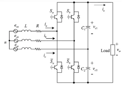
Fig. 1. Power circuit of the three-phase four-switch PWM voltage source rectifier.
Hence, recent study has been focused on developing high-performance VSRs with less switches and reduced loss. PWM VSRs that can offer the same functionality with only four active switching devices have been considered inAnother research trend has also focused on using the four-switch inverters for motor drives although four-switch PWM VSRs have the feature of structural simplicity and reduced cost, two main shortcomings of this topology merit discussion concerning practical application. First, with the same ac supply, the lower output voltage bound is normally much higher than that of a six-switch PWM VSR; for a four-switch PWM VSR with
100-Vrms ac source supplying line current 7.07 Arms, the output dc voltage may reach as much as 480V. Hence, the high output voltage feature limits its application. Second, as the third phase ac current flows through the split capacitor bank, two output capacitors with large capacities are required to keep the voltage ripples small. However, little research has studied on the modelling and control of the four-switch PWM rectifier. In the work of Sheet al. [15], under the assumption that the VSR operates at steady state, both a-b-c and d-q frame models are derived. A control strategy, called a closed-form controller, to achieve high power factor and near-sinusoidal input current waveforms is reported. As this controller design is based on the steady-state model, transient performance of the current loop is not considered. Kim and Lipo used this type of circuit configuration to form a low cost rectifier/inverter system with only eight switches for ac drives.
In, Chiang devises a linearized dynamical model upon which a hysteresis current control scheme to produce high output voltage is devised. The guidelines to select adequate passive elements such as an inductor and a dc-bus capacitor for a four-switch VSR to operate properly are also documented. Subsequently, an improved version with reduced number of hysteresis comparator is reported in. However, a major drawback of hysteresis current controller is that its switching frequency varies with dc-load current and the power switches are subject to additional stresses. proposes a proportional-plus-integral current controller with compensation for three phase unbalanced supply. By using a mixed p-z approach, mathematical expressions of the system responses is derived and verified experimentally. For a four-switch PWM inverter, efforts have also been made in to reduce the dc-bus voltage ripples with a space vector modulation technique under unbalanced ac power supply. In this paper, a model suitable for
the controller design in d-q synchronous frame for four-switch VSRs is derived. This model is developed based on the state space average model of [15], without any prespecified operating condition. The result relies on utilizing a so-called “reduced Park Transformation” on the switching functions. Except a term describing the voltage difference between the two output capacitor voltages, the derived model resembles that of a six-switch VSR. It is also shown that the modulation policy of the closed form controller developed in [15] corresponds to the steady-state control input of a given operating point. As an illustration of the salient performance of the current control approach in rotating d-q frame, the input–output feedback linearization (IOFL) [10], and LPI [3] controller designs are presented. Then following the usual practice, an outer-loop LPI voltage controller cascaded to the d-axis current loop is adopted to cope with the issue of voltage regulation. The performance of the proposed controller designs is validated through computer simulation and hardware experiment. To give a comparison, simulated and experimental results of an a-b-c frame LPI current controller [3] migrated from six-switch VSR are also provided to show the superiority of the proposed designs in synchronous rotating d-q frame.
II. SYSTEM MODELING IN ROTATING d-q FRAME
A. Coordinate Transformation
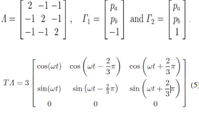
The Park Transformation converts the three-phase system from a stationary reference frame into synchronously rotating frame with direct, quadrature, and zero-sequence components. In this coordinates, as the d-axis is aligned with the source supply voltage, the unity-power-factor requirement can be achieved by simply regulating the q-axis source current to zero. Park Transformation has some variants. This paper considers the following transformation matrix
where ωt is the angle determined by the source supply voltage with angular frequency ω.
The reduced Park Transformation (3) converts d- and q-axis dc components into two sinusoidal signals with 60◦ out of phase from each other.
B. Modelling in rotating d-q Frame
The schematic diagram of a three-phase four-switch VSR under consideration is shown in Fig. 1. It is assumed that a resistive load RL is connected to the output terminal. Also, the two series-connected output capacitors are identical (i.e., C1 =C2 = C). As demonstrated in [15], assuming that esa + esb +esc = 0 and ia + ib + ic = 0, the a-b-c frame state equations of the four-switch VSR are represent the switching actions for the four switches. Denoting es = [esa esb esc] T, is = [ia ib ic] T, the a-b-c frame model in vector form can be expressed as (3)
Under a balanced three phase ac supply, neglecting the resistance of the power switches, and performing the Park’s Transformation matrix T on the both sides of the state equation (11) leads to
the transformed phase-to-neutral voltages in (4) is now simplified to
Denote the transformed variables [id iq 0] T= Tis and [Em 0 0] T= Test, withEm being the amplitude
of the phase
voltage. Substituting (6) into (4), the current dynamics of the four-switch VSR in the rotating d-q frame is obtained as
The expressions of the dc-bus voltage dynamics in the rotating d-q frame may be derived as follows. Applying the Park’s Transformation to the a-b-c frame state equations.
we have
As the two dc-bus capacitors are identical and vo= vc1 + vc2, the output voltage (8), (9) may be combined to a single one
Applying (4) to (9) again, and rearranging (6), the complete d−q frame model of the four-switch VSR is
state equations provide a mathematical model more
suitable for controller design.
As compared to the d-q frame model for a six-switch VSR [5], [7], [8], the capacitor voltage difference terms vcd and vcq are unique to the four-switch VSR. Accordingly, when there is no difference between capacitor voltages vc1 and vc2, vcd and vcq vanish, and the d-q frame model (11)– (13), is almost identical to that of a six-switch VSR. As using two identical capacitors in the capacitor bank, it is reasonable to assume that vc1 is equal to vc2 if the imperfection of the capacitors is ignored. Then, a wealth of analytical and control methods for the six-switch VSR may be directly applied to the four-switch VSR.
C. Steady-State Solution
The d-q frame model derived in Section II for four-switch VSRs is a two-input nonlinear system. With a resistive load RL connected at dc output, as dc-bus voltage vo reaches a given desired setting Vo∗with a unity power factor, the steady-state solution may be found as follows. The switching functions in d-q frame at steady state may be transformed back into a-b-c frame by the inverse reduced Park Transformation (3), i.e.,
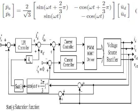
Fig. 2. Block diagram of the overall control system for control in d-q frame.
It can then be checked that the steady-state switching functions are the modulation policies of the closed-fromcontroller proposed in on the other hand, the steady-state d-axis source current may be solved as
In, it has been shown that the larger solution in
isnot a stable equilibrium point and hence not feasible.
Remark 2: When there is a failure of one bridge arm of a six-switch VSR, a practical application of this topology is to recover the functionality of the six-switch VSR with split dc link capacitors. In this situation, under the condition that the ac supply and dc load remain unchanged, the delivered power of this simplified VSR will increase since the lower output voltage bound of the four-switch VSR is normally much higher than that of a six-switch VSR. Typically, the lower output voltage bound of the four-switch VSR is increased by 173.2%. Thus, the simplified VSR will deliver power triple as much as that of the original six-switch PWM VSR.
III. CURRENT CONTROLLER DESIGNS
The expressions indicate that the dynamics of a four-switch VSR are nonlinear and bear a resemblance to that of a six-switch VSR. In fact, when vc1 = vc2, they are almost identical. Thus, many existing control strategies (for example, see may be adopted to design a controller that could exhibit satisfactory performance. Due to the non minimum phase property, the control of VSRs is usually accomplished in a cascaded structure as shown in Fig. 2. The inner loop performs current control and the outer-loop voltage controller generates a current reference for the inner current loops. To show the effectiveness of the current controller design in d-q frame, this section describes two current controller designs for four-switch VSRs, based on the d-q frame model derived in the previous section.
A. IOFL
The IOFL provides an effective means to transforming the original system into a linear one under which a regular linear controller design can be applied. In [10], the author has given a thorough analysis on the geometric properties of the six-switch VSR and discovered that the so-called voltage control, with output variables chosen to be vo and iq , leads to a non minimum phase system, and thus not feasible. Instead, the feedback linearization is considered for the d- and q-axis current dynamics.
inputs render the current loops be exponentially stable error dynamics. With a substitution of the current control laws into, the internal dynamics may be derived. Similar to the case of six-switch VSRs (see Section III-B of [10]), when the current tracking errors εd and εq approach zero, the zero dynamics may be shown to be stable.
2) Analysis of the Capacitor Voltage Difference Dynamics:By following the analysis in, it can be deduced that the voltage imbalance caused by the initial conditions asymptotically approaches zero with a settling time 4C/kc. Since in the steady state, the d-axis current id will eventually converge toi∗dm. Thus, a larger value of kc will lead to a faster settling time at the price of inducing a larger
vibration in d-axis current.
Remark 3: The compensating term udf in has singular points at ωt = 1/6(4 ± 3n) π, which will render the modified d-axis reference i∗dm be extremely large at these points. This undesired situation may be avoided by placing a limit on the value calculated from the inverse of the cosine functioncos (ωt + (2/3π)).
B. Linear PI ControlThis scheme employs LPI
controllers for both the d- andq-axis current loops [3]. The control policy is generating the modulating signal by performing proportional and integral operation on current tracking error. This method is simple and easy to be analogously or digitally implemented. The magnitude of the d-axis current reference i∗d is provided by the outer voltage loop.
The current controllers may be expressed as
Fig. 3. Block diagram of the closed-loop system for the d-axis current loop with LPI controller.
of the d- and q-axis current loops may be expressed as
where Ej(s) represents the Laplace transform of εj
(t). With the LPI controller (50), the block diagram of the closed-loop system for the d-axis loop is shown in Fig. 3. The q-axis loop is also with the same control structure and thus omitted here. It can be checked that the resulting closed-loop system is not a standard second-order system. According to] and our simulation study, the presence of the zero at s = −kij/kpj increases the bandwidth of the closed-loop system. In fact, it is discovered that as the location of the zero moves close to the origin, a higher bandwidth is achieved. This can be used as a guideline in choosing the ratio of the controller parameters. Then, the proportional gain is selected so that the open loop has an adequate bandwidth (about one-tenth of the switching frequency for good transient response.
IV. ANALYSIS OF THE EFFECT OF DISTORTED AC SUPPLY ON LINE CURRENTS
The salient performances of the proposed d-q frame current controllers are guaranteed under ideal ac supply. However, in the industrial power distribution system, harmonics distortion in supply voltage is not uncommon. Typically, the fifth- and the seventh-order harmonics are dominant component sin voltage. According to the analysis given in the effect of supply voltage distortion on line currents is analysed as follows.
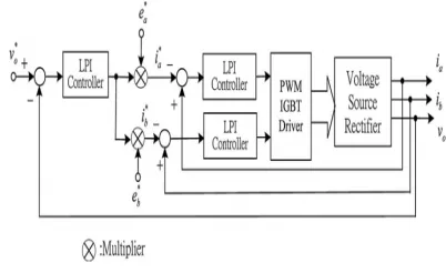
Fig. 4. Block diagram of the cascaded control system for control in an a-b-c frame.
V. INDUCTION MOTOR
wide speed range but also improves the starting performance. Synchronous speed of Induction Motor is directly proportional to the supply frequency. Hence, by changing the frequency, the synchronous speed and the motor speed can be controlled below and above the normal full load speed. If the machine is operating at speed below base speed, then v/f ratio is to be kept constant so that flux remains constant. This retains the torque capability of the machine at the same value. But at lower frequencies, the torque capability decrease and this drop in torque has to be compensated for increasing the applied voltage.Any reduction in the supply frequency without a change in the terminal voltage causes an increase in the air gap flux. Induction motors are designed to operate at the knee point of the magnetization characteristic to make full use of the magnetic material. Therefore the increase in flux will saturate the motor. This will increase the magnetizing current, distort the line current and voltage, increase the core loss and the stator copper loss, and produce a high pitch acoustic noise. While any increase in flux beyond rated value is undesirable from the consideration of saturation effects, a decrease in flux is also avoided to retain the torque capability of the motor. Therefore, the variable frequency control below the rated frequency is generally carried out
By reducing the machine phase voltage, V, along with the frequency in such a manner that the flux is maintained constant. Above the rated frequency, the motor is operated at a constant voltage because of the limitation imposed by stator insulation or by supply voltage limitations.
VI .MATLAB/SIMULINK RESULTS
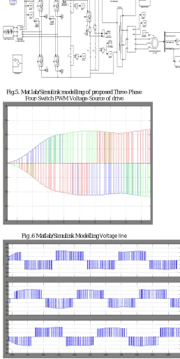
Fig.5. Mat lab/Simulink modelling of proposed Three-Phase Four-Switch PWM Voltage-Source of drive
Fig .6 Matlab/Simulink Modelling Voltage line
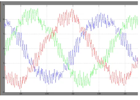
Fig .8 Matlab/Simulink Modelling line Current in circuit
Fig .9 Matlab/Simulink Modelling of Speed, torque and current for IM drive
VII. CONCLUSION
Controller designs in rotating d-q frame have been popular for six-switch VSRs in recent decades. For four-switch VSRs, this approach has not been received much attention, partly because it lacks of a precise model in the rotating d-q frame coordinates. By using a reduced Park Transformation on switching functions, this paper has derived a d-q frame model for a four-switch VSR, which bears a strong resemblance to that of a six-switch VSR. Thus, many existing control strategies for six-switch VSRs are readily applicable to four-six-switch VSRs. As a demonstration,the IOFL and LPI-DQ current controllers are designed to provide unity-power-factor operation, and verified through computer simulation and hardware experiment. Responses of a classical LPI-SF current controller in a b-c frame are also included as a comparison. The simulation and experimental results are in close agreement. The advantage of control in d-q frame is clearly demonstrated from the measured data. The LPI-SF current controller yields unbalanced line currents, larger dc-bus voltage ripples, and a nonzero phase tracking error. The LPI-DQ current controller delivers nearly sinusoidal and balanced line currents, and small
dc-bus voltage ripple, yet coupling between d- and q-axis current dynamics exists. Induction Motor drive is application and study characteristics of IM drive of speed, torque and current wave forms.
REFERENCES
[1] B. Singh, B. N. Singh, A. Chandra, K. Al-Haddad, A. Pandey, and D. P. Kothari, “A review of three-phase improved power quality AC– DC converters,” IEEE Trans. Ind. Electron., vol. 51, no. 3, pp. 641–660, Jun. 2004. [2] J. R. Rodriguez, J. W. Dixon, J. R. Espinoza, J. Pontt, and P. Lezana, “PWM regenerative rectifiers: State of the art,” IEEE Trans. Ind. Electron., vol. 52, no. 1, pp. 5–22, Feb. 2005. [3] N. R. Zargari and G. Joos, “Performance investigation of a current- ´ controlled voltage-regulated PWM rectifier in rotating and stationary frames,” IEEE Trans. Ind. Electron., vol. 42, no. 4,
pp. 396–401, Aug. 1995.
[4] P. Rioual, H. Pouliquen, and J. P. Louis, “Non-linear control of PWM rectifier by feedback linearization and exact PWM control,” Conf. Rec.IEEE Power Electron. Spec. Conf. (PESC), pp.
1095–1102, Jun. 1994.
[5] V. Blasko and V. Kaura, “A new mathematical model and control of a threephase AC–DC voltage source converter,” IEEE Trans. Power Electron., vol. 12, no. 1, pp. 116–123, Jan. 1997. [6] D. M. Vilathgamuwa, S. R. Wall, and R. D. Jackson, “Variable structure control of voltage sourced reversible rectifiers,” Proc. Inst. Elect. Eng.-Electric Power Appl., vol. 143, no. 1, pp. 18–
24, Jan. 1996.
[7] P. Verdelho and G. D. Marques, “DC voltage control and stability analysis of PWM voltage-type reversible rectifiers,” IEEE Trans. Ind. Electron., vol. 45, no. 2, pp. 263–273, Apr. 1998. [8] H. Kom ¨ urc ¨ ugil and O. K ¨ ukrer, Lyapunov-based control for three phase ¨ PWM AC/DC voltage–source converters,” IEEE Trans. Power Electron., vol. 13, no. 5, pp. 801–813, 1998. [9] D.-C. Lee, G.-M. Lee, and K.-D. Lee, “DC-Bus voltage control of threephase AC/DC PWM converters using feedback linearization,” IEEETrans. Ind. Appl., vol. 36, no. 3, pp. 826–833, May
2000.
“Passivity-based PI control of ´ switched power converters,” IEEE Trans. Control Syst. Technol., vol. 12, no. 6, pp. 881–890, Nov. 2004. [13] A. Gensior, H. Sira-Ram´ ırez, J. Rudolph, and H. Guldner, “On some ¨ nonlinear current controllers for three-phase boost rectifiers,” IEEE Trans.Ind. Electron., vol. 56, no. 2, pp. 360–370,
Feb. 2009.
[14] T.-S. Lee, “Nonlinear state feedback control design for three-phase PWM boost rectifiers using extended linearization,” Proc. Inst. Elect. EngElectric Power Appl., vol. 150, pp. 546–554,
Sep. 2003.
[15] J.-J. Shieh, C.-T. Pan, and Z.-J. Cuey, “Modelling and design of a reversible three-phase switching mode rectifier,” IEE Proc.-Elect. Power Appl., vol. 144, no. 6, pp. 389–396, Nov. 1997...
Author’s Profile:
V.B.S .V SURYA NARAYANA is an M.Tech candiadate at Avanthi College of Engineering & Technology under JNTU, Kakinada. He received his B.Tech degree from Pydah College of Engineering & Technology under JNTU Kakinada. His current Research interests are Permanent Magnet Synchronous Motor Drive System and its Application Multi level inverters
Applications & power Electronics Drive Applications.
T.srinivasarao is an Associate professor and head of the Department in Avanthi College of Engineering & Technology at Visakhapatnam. He is currently working towards ph.D. He got his M-Tech degree form GITAM University. His current research interests are power systems, power system analysis and Electrical Machines.