10.15662/ijareeie.2014.0311185
Performance Evaluation of VSI Based Active
Filter and Passive Filters
S. Sherine, S.P.Vijayaragavan
Assistant Professor, Dept. of EEE, Bharath University, Chennai, Tamil Nadu, India Assistant Professor, Dept. of EEE, Bharath University, Chennai, Tamil Nadu, India
ABSTRACT: The aim of this project is to simulate VSI based active power filters to Non-linear load for improving power quality. THD is used as measuring index for comparing performances of these filters. These filters can reduce harmonic in supply current. When a non-linear load is connected to an AC supply it produces a quasi square waveform which contains harmonic current. Thus, active filters injects harmonic currents and changes quasi-square waveform to sinusoidal current. In this work, SVM based the voltage source shunt active filters and passive filters are compared. The circuits are simulated using MATLAB simulink. Harmonic distortion is found to be lowest in the case of VSI filter.
I. INTRODUCTION
The growing number of power electronics base equipment has produced an important impact on the quality of electric power supply. Both high power industrial loads and domestic loads cause harmonics in the network voltages. At the same time, much of the equipments causing the disturbances is quite sensitive to deviations from the ideal sinusoidal line voltage.[1] Therefore, power quality problems may originate in the system or may be caused by the consumer itself.
Consumers that are becoming increasingly aware of the power quality issues and being more informed about the consequences of harmonics, interruptions, sags, switching transients, etc. Motivated by deregulation, they are challenging the energy suppliers to improve the quality of the power delivered.[2-4]
The technology of active power filter has been developed during the past two decades reaching maturity for harmonics compensation, reactive power, voltage balance in ac power networks. All active power filters are developed with PWM inverters (current source or voltage source inverters). The current fed PWM inverter bridge structure behaves as a sinusoidal current source to meet the harmonic current requirement of the non-linear load. It has a self supported dc capacitor that ensures the continuous circulation of the dc current. They present good reliability and require higher values of parallel capacitor filters at the ac terminals to remove unwanted current harmonics.[5] However, they cannot be used in multilevel or multistep diodes configurations to allow compensation in higher power ratings. The other converters used in active power filters topologies is the voltage-source PWM inverter. This converter is more convenient for active power filtering applications since it is lighter, cheaper, expandable to multilevel and multistep versions, to improve its performance for high power rating compensation with lower switching frequencies. The PWM voltage source inverter has to be connected to the ac mains through the coupling reactors. An electrolytic capacitor keeps a dc voltage constant and ripple free.
II. ACTIVE FILTERS
A. Voltage-Source Active Power Filter
The PWM bridge consists of six controllable switches (IGBTs) with antiparallel diodes. The voltage-source topology requires the filter to be placed between the supply and the PWM bridge. The filter has usually either first order(L) or third-order (LCL) structure. More-over, the filter makes it possible to control the currents. In the dc link there is an electrolytic capacitor with a dc voltage as an energy storage. The limited lifetime of the electrolytic capacitor can be considered a disadvantage.[9] The dc link voltage should be so high that the filter currents can be controlled to draw the load current harmonics through the supply filter.[10]
Fig Voltage Source Shunt Active filter.
III. PASSIVE HARMONIC FILTERS
Passive harmonic filters work on the principle of electrical resonance in tuned circuits which is useful in mitigating harmonic orders corresponding to a particular frequency.[11-12] The concept is that at resonant frequency the tuned RLC circuit considered to be the passive filter provides a least resistance path for the harmonic current to flow out of the system that feeds the loads. Thus it reduces harmonics in the system. [13]The impedance offered by the filters is minimum and purely influenced only by the resistive nature of the circuit at resonance conditions. Thus maximum current corresponding to the harmonic order is filtered out from the path that feeds the loads.
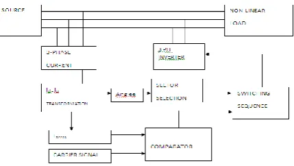
IV. SPACE VECTOR MODULATION (SVM)
10.15662/ijareeie.2014.0311185
Fig. Switching vectors and applied sequence of vectors when the reference vectors lies in sector I in the case of fig1 voltage-source PWM bridge.
IV. SIMULATION RESULTS
FFT Analysis without filter
FFT Analysis with VSI SVM filter
The fig represents the FFT Analysis with VSI SVM filter and found that the THD content is reduced to 3.33%. Thus the THD content is reduced with the use of SVM based VSI filter than the use of SVM based VSI filter
V. CONCLUSION AND SCOPE FOR FUTRE WORK
CONCLUSION:
Highly inductive load is connected at the output of the rectifier. The A.C current drawn by the rectifier is Non-linear as shown in fig 6.a. The current drawn is quasi-sinusoidal current, thus the load acts as a Non-Non-linear load. The harmonic distortion is found to be 24.68%.
When the power system is fed with CSI SVM filter the harmonic content is found as 3.57% and when it is fed with VSI SVM filter the harmonic the harmonic content is found as 3.33%. Thus the THD content is found to be reduced with the use of SVM based VSI filters.
In this work Vector modulated voltage source inverter and Passive filters are compared and found that VSI filter is best among the two. The harmonics are eliminated more in volage source inverter than passive filters has high on-state losses and inefficient inductive energy storage element on the DC side of the bridge.
Thus Harmonic distortion is found to be lowest in the case of VSI filter and hence it is widely used in industrial applications.
FUTURE WORK:
10.15662/ijareeie.2014.0311185 REFRENCES
[1] H. Akagi, ―New trends in active filters for power conditioning,‖ IEEE Trans. Ind. Appl., vol. 32, no. 6, pp. 1312–1322, Nov./Dec. 1996.
[2] Y. Hayashi, N. Sato, and K. Takahashi, ―A novel control of a currentsource active filter for ac power system harmonic compensation,‖ IEEE
Trans. Ind. Appl., vol. 27, no. 2, pp. 380–385, Mar./Apr. 1991.
[3]Mahalakshmi K., Prabhakar J., Sukumaran V.G., "Antibacterial activity of Triphala, GTP & Curcumin on Enterococci faecalis", Biomedicine, ISSN : 0970 2067, 26(Mar-4) (2012) pp. 43-46.
[4]Bhuvaneswari B., Hari R., Vasuki R., Suguna, "Antioxidant and antihepatotoxic activities of ethanolic extract of Solanum torvum", Asian Journal of Pharmaceutical and Clinical Research, ISSN : 0974-2441, 5(S3) (2012) pp. 147-150.
[5]Sathyanarayana H.P., Premkumar S., Manjula W.S., "Assessment of maximum voluntary bite force in adults with normal occlusion and different types of malocclusions", Journal of Contemporary Dental Practice, ISSN : 1526-3711, 13(4) (2012) pp.534-538.
[6]Selva Kumar S., Ram Krishna Rao M., Deepak Kumar R., Panwar S., Prasad C.S., "Biocontrol by plant growth promoting rhizobacteria against black scurf and stem canker disease of potato caused by Rhizoctonia solani", Archives of Phytopathology and Plant Protection, ISSN : 0323-5408, 46(4) (2013) pp.487-502.
[7]Hariharan V.S., Nandlal B., Srilatha K.T., "Efficacy of various root canal irrigants on removal of smear layer in the primary root canals after hand instrumentation: A scanning electron microscopy study", Journal of Indian Society of Pedodontics and Preventive Dentistry, ISSN : 0970-4388, 28(4) (2010) pp.271-277.
[8] M.-X. Wang and H. Pouliquen, ―Performance of an active filter using PWM current source inverter,‖ in Proc. 5th Eur. Conf. Power Electron.
Appl. (EPE’93), Sep. 13–16, 1993, vol. 8, pp. 218–223.
[9] H. Akagi, ―Trends in active power line conditioners,‖ IEEE Trans.Power Electron., vol. 9, no. 3, pp. 263–268, May 1994.
[10] T. Halkosaari and H. Tuusa, ―Optimal vector modulation of a PWM current source converter according to minimal switching losses,‖ in Proc.
31st Annu. Power Electron. Spec. Conf. (PESC’00), Jun. 18–23, 2000, vol. 1, pp. 127–132.
[11] M. Routimo, M. Salo, and H. Tuusa, ―A control delay compensation method for voltage source active power filter,‖ in Proc. 9th Eur. Power
Qual. Conf. (PCIM’03 Eur.), May 20–22, 2003, pp. 93–97.
[12] M. Salo and H. Tuusa, ―A novel open-loop control method for a current- source active power filter,‖ IEEE Trans. Ind. Electron., vol. 50, no. 2,
pp. 313–321, Apr. 2003.
[13] M. Lindgren and J. Svensson, ―Control of a voltage-source converter connected to the grid through an LCL-filter—applicatio n to active
filtering,‖ in Proc. 29th Annu. Power Electron. Spec. Conf. (PESC’98), May 17–22, 1998, vol. 1, pp. 229–235.
[14]Thooyamani, K.P., Khanaa, V., Udayakumar, R., "Wireless cellular communication using 100 nanometers spintronics device based VLSI", Middle - East Journal of Scientific Research, v-20, i-12, pp:2037-2041, 2014.
[15]Vanangamudi, S., Prabhakar, S., Thamotharan, C., Anbazhagan, R., "Dual fuel hybrid bike", Middle - East Journal of Scientific Research, v-20,
i-12, pp:1819-1822, 2014.
[16]Udayakumar, R., Kaliyamurthie, K.P., Khanaa, Thooyamani, K.P., "Data mining a boon: Predictive system for university topper women in academia", World Applied Sciences Journal, v-29, i-14, pp:86-90, 2014.
[17]Satheesh, S., Lingeswaran, K., "High efficiencytransformer less inverter for single-phase photovoltaic systems using switching converter", Middle - East Journal of Scientific Research, v-20, i-8, pp:956-965, 2014.