ISSN(Online): 2319-8753 ISSN (Print): 2347-6710
I
nternational
J
ournal of
I
nnovative
R
esearch in
S
cience,
E
ngineering and
T
echnology
(A High Impact Factor, Monthly, Peer Reviewed Journal)
Visit: www.ijirset.com
Vol. 6, Issue 10, October 2017
Control Plan of Flyback Micro-Inverter with
Controllers for PV AC Components
V Kalyani1, K. Neelima Praveena2
P.G. Scholar, Department of Electrical Engineering, Malla Reddy Engineering College, Hyderabad, Telangana, India1
Assistant Professor, Department of Electrical Engineering, Malla Reddy Engineering College, Hyderabad,
Telangana, India2
ABSTRACT: In this thesis, we control the output of flyback micro inverter with controllers. The suggested control plan involves two components. The proportional-resonant controller (PR) with the harmonic compensator and hybrid nominal duty ratio Associated to the conventional control plan using the proportional-integral controller (PI). The proportional-resonant controller with the harmonic compensator brings higher system gain without using high proportional gain in two modes. It delivers high system gain at the fundamental and harmonic frequencies of the grid. Then it enriches the tracking speed, and disturbance rejection performance is satisfying the desired stability. In the suggested control plan hybrid nominal duty ratio reduces the disturbance rejections, and also control burden. But the combination of proportional integral controller and second-order low-pass filter gives less total harmonic distortion compared with the suggested one. Finally, the simulation was shown to verify the tracking speed, and disturbance rejection performances of the suggested control plan, and total harmonic distortion was shown to confirm the benefits of the combination of Proportional integral controller and second-order filter.
KEYWORDS:Index Terms-System gain, tracking speed, disturbance rejection, total harmonic distortion, PV module.
I.INTRODUCTION
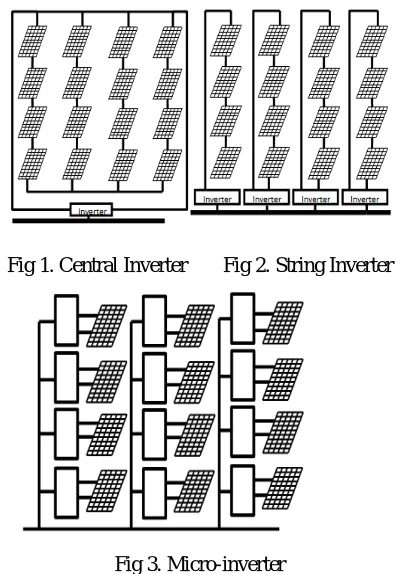
Renewable energy generates from renewable energy resources. It is a natural process, and also it is naturally replenished on a human period, such as sunlight, rain, wind, waves, tides, and geothermal heat. Due to the so many advantages of renewable energy sources the PV energy became the part of so many industrial fields. The PV power systems can be categorized into centralized, AC, and string module system. Among them in the AC module system, a low-power grid-connected inverter called as the micro-inverter is mounted on single PV module. By PV module mismatch and partial shading, it can reduce the power losses, and also it can track the individual maximum power point. Comparing to centralized, string module systems the ac module system has higher reliability and easier maintenance. The future PV power system is the ac module system because of these advantages. A solar micro-inverter, or simply micro-micro-inverter, is a device used in photovoltaic that converts direct current (DC) generated by a single solar unit to alternating current (AC). The output from several micro-inverters is combined and often fed to the electrical grid. Micro-inverters difference with conventional string and central solar inverters, which are connected to multiple solar units or panels of the PV system. In micro-inverter designs, to perform power conversion on each module each solar panel has its own inverter. Micro-inverter architectures are costlier than the other two, but gives the highest power optimization and design flexibility and also avoid a single point of failure. Micro-inverters that are based on the flyback converter topology.
ISSN(Online): 2319-8753 ISSN (Print): 2347-6710
I
nternational
J
ournal of
I
nnovative
R
esearch in
S
cience,
E
ngineering and
T
echnology
(A High Impact Factor, Monthly, Peer Reviewed Journal)
Visit: www.ijirset.com
Vol. 6, Issue 10, October 2017
Fig 1. Central Inverter Fig 2. String Inverter
Fig 3. Micro-inverter
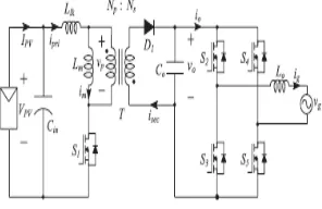
The flyback converter is postponement of the Buck-Boost converter. The fly back converter is built by replacing inductor with the transformer in Buck-Boost converter. The flyback converter is used in both alternating currents to direct current and direct current to direct current conversion with galvanic isolation between the input and any outputs. The power conversion efficiency, the shape of output current, power density, reliability, and cost to obtain these advantages, a single stage fly back inverter topology has been adopted. The flyback inverter has simple circuit structure and potential for high efficiency and reliability. The flyback inverter has both the functions. First one is step-up function and, another one is step down function. The main characteristic for the PV applications is the step-down and step-up functions. The various conduction modes in which fly back operated are DCM (Discontinuous Conduction Mode), CCM (Continues Conduction Mode). The flyback inverter operate in discontinues conduction mode at a low level of power to make fewer losses or solar level. At all instantaneous power level, fly back operate in Continues Conduction Mode. For reducing the converter losses, the converter has to operate in continuous conduction mode along with magnetizing mode. When the converter is in CCM, the output current handle becomes tuff. Because the right half plane becomes zero in the transfer function. To make sure to not get into situations like distorted output current, the controller has to apply with the complex control scheme. By these, PV inverters which are cheap are not suitable to work in CCM.
ISSN(Online): 2319-8753 ISSN (Print): 2347-6710
I
nternational
J
ournal of
I
nnovative
R
esearch in
S
cience,
E
ngineering and
T
echnology
(A High Impact Factor, Monthly, Peer Reviewed Journal)
Visit: www.ijirset.com
Vol. 6, Issue 10, October 2017
required. The control gain is limited by the RHP zero in CCM with the conventional PI controller. As a result, it causes unacceptable power quality and high total harmonic distortion (THD) by the poor control performance in DCM. That is the reason why the use of the flyback inverter with conventional control plan is restricted despite its many dis advantages. But the combination of PI controller with second order filter gives total harmonic distortion to very lesser value compared with PI controller and PR controller. The PR controller means proportional resonant controller.
Fig 1. Circuit diagram of the flyback micro-inverter
The PR controller is resonant at the selected frequency. The PR controller is an alternative to the PI controller. The proportional resonant controller (PR) delivers an infinite gain at a selected resonant frequency only without using high proportional gain. The PR controller with the hybrid nominal duty ratio gives faster dynamics, and more effective disturbance rejection. Thus, the suggested control plan gives the better disturbance rejection, and higher tracking performance. In both operation modes the flyback inverter strengthens the many advantages of the flyback with hybrid mode. In the control plan of flyback micro inverter, the current control strategy of the flyback micro-inverter with the hybrid mode is proposed. The suggested control plan consists of two components, the PR controller with the hybrid nominal duty ratio. The PR controller with hybrid nominal duty ratio provides a high gain at the fundamental and harmonic frequencies of the grid and achieves the zero-tracking error in both operation modes. The hybrid nominal duty ratio performs as a feed-forward control input and is determined by the proposed operation mode selection. By applying the hybrid nominal duty ratio according to the proper operation region, it can achieve more effective disturbance rejection and faster dynamics.
II. OPERATION OF THE FLYBACKINVERTER WITH HYBRID MODE
ISSN(Online): 2319-8753 ISSN (Print): 2347-6710
I
nternational
J
ournal of
I
nnovative
R
esearch in
S
cience,
E
ngineering and
T
echnology
(A High Impact Factor, Monthly, Peer Reviewed Journal)
Visit: www.ijirset.com
Vol. 6, Issue 10, October 2017
for a controlling rail which has to be loaded before the load is applied to the uncontrolled rails, this is to allow the PWM to open up and supply enough energy to the transformer.
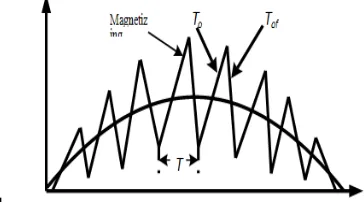
Fig. 2. Continuous conduction mode of magnetizing current
Fig. 3. Dis continuous conduction mode of magnetizing current
Under the constant switching frequency fs, the operation modes are classified into DCM and CCM. In DCM, the magnetizing current Im becomes zero within each switching period Ts, and the transformer T is completely demagnetized as shown in Fig. 4. When S1 is turned on, the primary current Ipri is stored in the magnetizing inductance Lm, and its peak value is expressed as follows.
, _ ( )= ( )
Where DDCM is the duty ratio in DCM. The energy ELmstored in Lm is express as
=1
2 , ( ) =
( ( ) )
2
Assuming lossless operation in the inverter, the power balance equations can be obtained as
= =
( ) = ( ) ( ) = sin
Where Vpv and Ipv are the average values of the voltage and current for a PV module. Vgand Igare the grid voltage and
ISSN(Online): 2319-8753 ISSN (Print): 2347-6710
I
nternational
J
ournal of
I
nnovative
R
esearch in
S
cience,
E
ngineering and
T
echnology
(A High Impact Factor, Monthly, Peer Reviewed Journal)
Visit: www.ijirset.com
Vol. 6, Issue 10, October 2017
the average primary current. ω is the angular frequency of the grid voltage. If there is no loss, the energy stored in Lm
is equal to the energy transferred to the grid. Assuming |vg| ≈ vo, from (2) – (4), DDCM can be derived as
( ) = 2 |sin |
Where DDCM, pk is the peak value of DDCM. In CCM, Lm is applied to VPV during the turn-on time of S1, while the voltage across Lm is reflected the output voltage during the turn-off time. Using the voltage-seconds law for Lm, the duty ratio DCCM in CCM is calculated as
( ) = |sin |
+ |sin |
The duties DDCM and DCCM determine the relationship between the input voltage VPV and output voltage Vo. The flyback operates in the DCM region when DDCM is smaller than DCCM. Fig 4. shows the operation regions of the flyback inverter in a half-cycle of the grid. As shown in Fig. 4, the flyback inverter operates in DCM at the low instantaneous power level or low solar irradiation level, although it operates in the CCM region above a certain power level in the ac line period. Because the flyback inverter has both operation modes over the whole ac line period, it performs as the flyback inverter with the hybrid mode. The boundary between the DCM and CCM regions varies according to the magnetizing inductance Lm. A lower Lm results in a larger DCM region at the given output power. Theaccording to the magnetizing inductance Lm. A lower Lmresults in a larger DCM region at the given output power.
Fig. 4. The operation regions of flyback micro-inverter with grid voltage
III. CONTROL PLAN OF FLYBACK INVERTER WITH CONTROLLERS
A. PI controller
A PI controller system is a kind of linear feedback control system. Smaller steady-state error, i.e., better referencefollowing
Faster dynamics, i.e., broader signal frequency band of the closed loop system and larger sensitivity concerning measuringnoise
ISSN(Online): 2319-8753 ISSN (Print): 2347-6710
I
nternational
J
ournal of
I
nnovative
R
esearch in
S
cience,
E
ngineering and
T
echnology
(A High Impact Factor, Monthly, Peer Reviewed Journal)
Visit: www.ijirset.com
Vol. 6, Issue 10, October 2017
Fig. 5. PI controller
B. PR Controller
Fig. 6. PR controller
This is an overview of grid-connected renewable system is present. In the suggested control plan two current-control strategies is present. Firstly, the d-q control in the rotating synchronous reference frame using proportional integral regulators. Secondly the proportional resonant controller in the stationary reference frame. To obtain a high efficiency of the system, a harmonic compensator structure is used along with PR controller. A phase-look loop is for synchronization algorithm.
IV.SIMULATION AND EXPERIMENTAL RESULTS
ISSN(Online): 2319-8753 ISSN (Print): 2347-6710
I
nternational
J
ournal of
I
nnovative
R
esearch in
S
cience,
E
ngineering and
T
echnology
(A High Impact Factor, Monthly, Peer Reviewed Journal)
Visit: www.ijirset.com
Vol. 6, Issue 10, October 2017
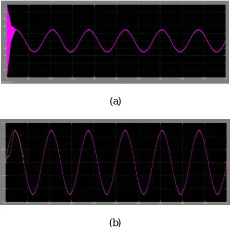
(b)
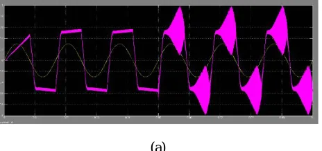
Fig. 7. Simulation results for the grid current Ig andIgrefwith conventional control plan (a)Quarter load condition. (b)Full load condition
Above Fig. 7. Is the simulation results for the grid current Ig and Igref with the conventional control plan for the quarter load condition and for the full load condition. According to the simulation results it’s clearly reveals that disturbances are high by using the conventional control plan, and also the harmonic distortion is high in theconventional control plan.
(a)
(b)
Fig. 8. Simulation results of grid current Ig,Igrefwith suggested control plan (a)Quarter load condition. (b)Full load condition
ISSN(Online): 2319-8753 ISSN (Print): 2347-6710
I
nternational
J
ournal of
I
nnovative
R
esearch in
S
cience,
E
ngineering and
T
echnology
(A High Impact Factor, Monthly, Peer Reviewed Journal)
Visit: www.ijirset.com
Vol. 6, Issue 10, October 2017
(a)
(b)
Fig. 9. FFT analysis (a) PR controller (b)The combination of PI,2nd order filter
Table. 1
Type of controller THD (%)
PI controller 26.78%
PR controller 24.54%
PI,2ND order filter 04.09%
ISSN(Online): 2319-8753 ISSN (Print): 2347-6710
I
nternational
J
ournal of
I
nnovative
R
esearch in
S
cience,
E
ngineering and
T
echnology
(A High Impact Factor, Monthly, Peer Reviewed Journal)
Visit: www.ijirset.com
Vol. 6, Issue 10, October 2017
controller with 2nd order filter will give total harmonic distortion to the smaller value as shown in table 1. As shown in Fig 9 the total harmonic distortion varies from PR controller to the combination of PI controller and second order filter.
V. CONCLUSION
The current control plan of the flyback micro-inverter with controllers for PV AC module is verified by the simulation, analysis, and experimental results. In the suggested control plan, the PR controller with HC provides the high system gain at fundamental and harmonic frequencies in both operation modes without using high proportional gain. The characteristic alleviates the trade-off between the control performance in DCM and stability in CCM when the conventional PI controller is used. Also, the proposed hybrid nominal duty ratio yielded from the proposed operation mode selection eliminates the disturbance more effectively and reduces the burden of the feedback controller. Flyback inverter with PI and second order filter gives total harmonic distortion to smaller value compared with the suggested control plan. From the simulation and experiment results, it is verified that the suggested control plan shows faster reference tracking and better disturbance rejection than those of the conventional plan. The suggested control plan encourages the many advantages of the flyback inverter with hybrid mode and makes it be used in the industrial field. The PI controller with the second order filter gives harmonic distortion to the smaller value.
REFERENCES
[1] Y. –H. Kim, J. –W. Jang, S. –C. Shin, and C. –Y. Won, “Weighted-efficiency enhancement control for a photovoltaic AC module interleaved flyback inverter using a synchronous rectifier,” IEEE Trans. Power Electron., vol. 29, no .12, pp. 6481–6493. Dec. 2014.
[2] G. Petrone, G. Spagnuolo, and M. Vitelli, “An analog technique for distributed MPPT PV applications,” IEEE Trans. Ind. Electron., vol. 59, no. 12, pp. 4713-4722, Dec. 2012.
[3] H. –J. Chiu, Y. –K. Lo, C. –Y. Yang, S. –J. Cheng, C. –M. Huang, C. –C. Chuang, M. –C. Kuo, Y. –M. Huang, Y. –B. Jean, and Y. –C. Huang, “A module- integrated isolated solar micro-inverter,” IEEE Trans. Ind. Electron., vol. 60, no. 2, pp. 781-788, Feb. 2013.
[4] N. Sukesh, M. Pahlevaninezhad, and P. K. Jain, “Analysis and implementation of a single-stage fly-back PV micro-inverter with soft switching,” IEEE Trans. Ind. Electron., vol. 61, no .4, pp. 1819–1833. Dec. 2014.
[5] M. Gao, M. Chen, C. Zhang, and Z. Qian, “Analysis and implementation of an improved flyback inverter for photovoltaic ac module applications,” IEEE Trans. Power. Electron., vol. 29, no .7, pp. 3428–3444. Jul. 2014.
[6] A.C. Nanakos, E. C. Tatakis, and N. P. Papanicolaou, “A weighted-efficiency-oriented design methodology of flyback inverter for ac photovoltaic modules,” IEEE Trans. Power. Electro., vol. 27, no .7, pp. 3221–3233. Jul. 2012.
[7] T. Shimizu, K. Wada, and N. Nakamura, “A flyback type single phase utility interactive inverter with low-frequency ripple current reduction on the dc input for an AC photovoltaic module system,” in Proc. Power Electron. Spec. Conf. (PESC), 2002, pp. 1483–1488.
[8] W. J. Cha, C. Y. Cho, J. M. Kwon, and B. H. Kwon, “Highly-efficient micro-inverter with soft-switching step-up converter and single-switch modulation inverter,” IEEE Trans. Ind. Electron., vol. 62, no. 6, pp. 3516- 3523. Jun. 2015.
[9] Z. Zhang, X. – F. He, and Y. –F. Liu, “An optimal control method for photovoltaic grid-tied-interleaved flyback micro-inverters to achieve high efficiency in wide load range,” IEEE Trans. Power. Electron, vol. 28, no .11, pp.
[10] Y.-H. Kim, Y.-H. Ji, J.-G. Kim, Y.-C. Jung, and C.-Y. Won, “A new controlstrategy for improving weighted efficiency in photovoltaic ac module-typeinterleaved fly back inverter,” IEEE Trans. Power. Electron., vol. 28, no. 6,
pp. 2688–2699. Jun. 2013.