Design and Analysis of Boom Structure of a
Backhoe Loader
Hemanth Kumar BL1, Nagesh N 2
M.Tech. Student, Department of Mechanical Engineering, Kuppam Engineering College, KES .Nagar,
Andhra Pradesh, India1
Assistant Professor, Department of Mechanical Engineering, Kuppam Engineering College, KES .Nagar,
Andhra Pradesh, India 2
ABSTRACT: With the increased requirement of accuracy of pay loads, the stiffness characteristics of structure are increasingly influencing the design and performance of a backhoe loader. The main objective of structural design is to achieve the minimum mass structure, which will satisfy the stiffness, strength and other requirements. Hence optimum configuration and advanced technology have to be incorporated to achieve minimum mass. In this study, static structural analysis of backhoe-loader arms has been performed with the finite element method (FEM). The aim of this study is to simulate and strengthen the back and front arms of the backhoe-loader concerning with stress under maximum loading condition and different boundary conditions. According to analysis result, back and front arms of the backhoe-loader are strengthened with the use of reinforcements. As a result of the study, strength of the arms has been increased by nearly 20%.
KEYWORDS: Design and Analysis.
I. INTRODUCTION
Fig: 1.1 Backhoe-Loader
improve the design before producing prototypes. The analysis has been carried out using ANSYS Workbench finite element packet program. Maximum stress locations and reinforcement were both determined and applied. Strength of the arms has been increased after improvements.
II.RELATEDWORK
2.1 PROBLEM DESCRIPTION
Finite element analysis is a word used in recent language of Mechanical Engineer in which the problems are solved with the use of software using Finite element method to solve the difficult problems where the direct implication of the problem is not always ready in the formula’s provided in the standards or the books. The Finite element method is a numerical procedure which can be used to solve numerical problems in Engineering. An unsophisticated description of the FE method is that it involves cutting a structure into several elements (pieces of the structure), describing the behaviour of each element in a simple way, than reconnecting elements at “nodes” as if nodes were pins or drops of glue that holds together the elements. This process results in the set of simultaneous algebraic equations which can be solved with mathematical formulations for solving the problem for deflection which can be further solved to get the results of strains and stresses. There may be several and thousands of such equations formed which means the computer implication is mandatory. A more sophisticated description of the FE method regards it as piecewise polynomial interpolation. That is over an element a field quantity such as displacement is interpolated from values of the field quantity at nodes.
2.2 DESIGN CRITERIA
Assumptions used in the analysis are:
• Material behavior is linear elastic and strains are small. Therefore, linear elastic analysis will be carried out.
• Pins and links are assumed as rigid.
• The loads are applied statically
• Material properties of structures after heat treatment (welding operation) are not changing.
According to loader and bucket cylinder maximum pressure, breakout forces (Wbf) were calculated using free body
diagrams, Maximum breakout force was obtained and it was used in the analysis of the front arm with two different boundary conditions.
2.3 AIM AND SCOPE OF THE PROJECT
To find the deformation and stress developed and verify the design of the Boom of backhoe loader for the given conditions.
This project work is mainly carried out for satisfying the following objectives:
Conduct various case studies for finalizing the design of boom
Carry out static analysic and extract the maximum stresses, strains, margin of safety and maximum displacement for the loads.
III.DESIGN AND FEANALYSIS OF BOOM STRUCTURE OF A BACKHOE LOADER
3.1MODELDESCRIPTION:
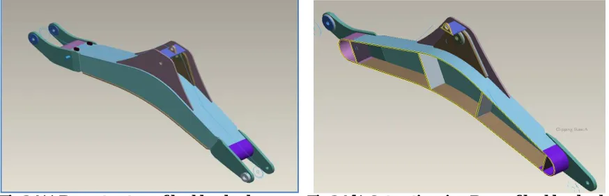
The boom of Backhoe loader assembly is shown in the figure The Boom swinger connected to the rear chassis and the other end is connected to the arm. It is also connected to the lift cylinder.
Fig 3.1(a) Boom structure of backhoe loader Fig 3.1(b) Cut section view-Boom of backhoeloader
3.2 ANALYSIS PROCEDURE
3.2.1 Analysis Preference: Structural (Static)
3.2.2 Elements used:
Element Remarks
SOLID 92 (10-noded tetrahedral)
DOF available: UX, UY, UZ
SOLID 92 element is giving better accuracy for the model with complex shape.
SURF 154 (8-noded)
DOF available: UX, UY, UZ
Used to define the surface loads like reaction forces of pin MASS 21
(1-mass node)
DOF available: UX, UY, UZ, Rot X, Rot Y, Rot Z
Used for introducing additional rotation DOF to solid elements specifically at the holding pivots
LINK 8 (2-noded)
DOF available: UX, UY, UZ
Used for defining the hydraulic cylinder as rigid link
3.2.3 Real Constant:
Element Real Constant
SURF 154 Unit thickness is given in all the nodes
TKI = TKJ = TKK = TKL = 1
MASS 21 Unit mass in all the directions:
MASS X = MASS Y = MASS Z = 1
LINK 8 To have high stiffness, cross sectional area more than the actual value is specified.
Table 3.2 Real Constants used for Analysis
3.2.4 Material Properties:
Elastic modulus = 2.1 x 10⁵ N/mm2; Poisson’s ratio = 0.3
Part Material
BOOM STOPPER(13) MS010102
LIFTING HOOK((12) MS010102
ROD BOOM LOCK(14) MS012008-Fe410WA
OTHER PARTS MS010201
Table 3.3 Material Properties considered for Analysis
3.2.5 FE Model Details:
The boom stoppers are suppressed for the analysis as they are not the load carrying members.
The MASS21 is created at the center pivot of the boom swinger and center pivot of the boom cylinder.
The constraint Equation are defined between Solid 92 and Mass 21 at the Boom swinger The link element is
modeled to simulate the tilt of the cylinder as rigid link and the constraint equations are defined between the
LINK8, MASS2 and Solid 92 at the boom cylinder pivot
Fig 3.2(a) Figure shows FE Model links Fig 3.2(b)Figure shows FE Model Constraints
3.3 BOUNDARY CONDITION:
The boom swing pivot side is given hinged condition and all the translational DOF and X & Y rotation DOF are arrested at this hinged support.
Both end of the link is fixed arresting all DOF
3.4 LOADING CONDITION:
Load case1:
Crowding condition:
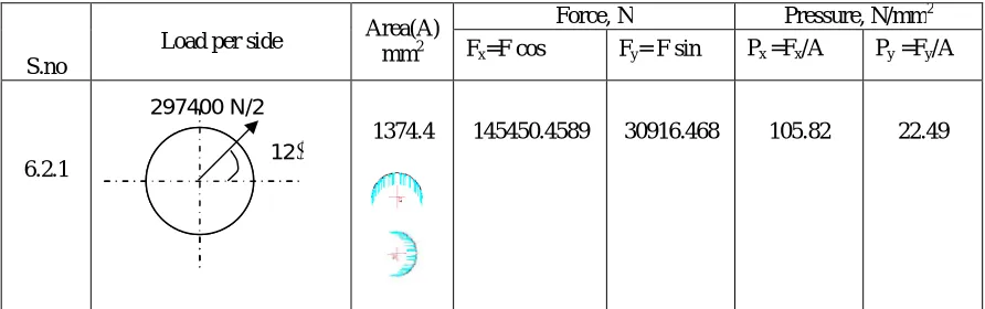
In crowding condition, the force of 297400 N are applied at the boom arm pivot. These forces are resolved into two components (Fx and Fy) and applied as surface load (pressure) along X and Y directions.
S.no
Load per side Area(A)
mm2
Force, N Pressure, N/mm2
Fx=F cos Fy= F sin Px =Fx/A Py =Fy/A
6.2.1
1374.4 145450.4589 30916.468 105.82 22.49
Table 3.4 Shows loads applied during Crowding Condition
12
Load case2: Digging condition:
In digging condition, the force of 256600 N is applied at the boom arm pivot. These force are resolved into two components (Fx and Fy) and applied as surface load (pressure) along X and Y directions.
S.no
Load per side Area(A)
mm2
Force, N Pressure, N/mm2
Fx=F cos Fy= Fsin Px =Fx/A Py =Fy/A
6.2.2
1374.4 127051.393 17855.908 92.44 12.99
Table 3.5 Shows loads applied during Digging Condition
IV. RESULTS AND DISCUSSIONS
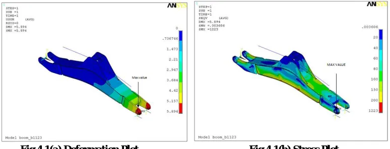
Load case 1: Deformation plot:
The deformation plot for this load case is given in fig.4.1(a)The Maximum deflection is 5.894 on the End Lug Plate .
Stress plot:
The maximum value of von mises stress is 1223 N/mm2 at the weld between Bottom Plate and arm end lug plate .The high stress is due to singularity errorshown in fig 4.1(b)
Fig 4.1(a) Deformation Plot Fig 4.1(b) Stress Plot
8
Load case2: Deformation Plot:
The Maximum deflection is 1.77 on the Arm End Lug Plate.
Stress Plot:
The maximum value of von mises stress is 399.548 N/mm2 at the weld between Bottom Plate and arm end lug plate (lhs).The high stress is due to singularity error.
Fig 4.2(a) Deformation Plot Fig 4.2(b) Stress Plot
V. CONCLUSION
The Deformation and Stress plot for the Backhoe Boom are obtained from the above analysis. The stresses are less than the fatigue strength of the material.
The design of Backhoe Boom assembly is ok. .
REFERENCES
[1] R.D. Cook and John Wiley and sons “Concepts and Application of FE analysis” [2] Robert M.Jones, “Mechanics of Composite Materials”, McGraw-Hill Book Co.Ltd,1975 [3] Finite Element Modeling (2005) Ansys User’s Guide and Reference Manual. [4] William T.Thomson, “Theory of vibration with applications”, Prentice Hall. [5] www.vitkovicemachinery.com/en/references/steel-structures-and-constructions. [6] www.aarokohonen.com.
[7] www.lindab-buildings.com/steelstructure. [8] www.steelstructures.co.za.
[9] www.engineeringtalk.com/guides/earth-moving-equipment.
[10]Angelos Tsinas,Efficient , Efficient satellite structural design optimized for volume production, Kingston University ,Friars Avenue, Roehampton Vale, London UK.
[11] D.H.Pahr, Institute of Lightweight Design and Structural Biomechanics,Vienna University of Technology, Austria, Materials Science Forum Vols. 539-543 pp. 2467-2472,2007.
[12] John. E.Higgins and James L.Harvey, Development of low cost lightweight tooling for large composite structures, 48 th AIAA,vol 8,2007. [13] Prof.I.Verpoest and Dr.J.Pflung, Investigation of a new Core-Skin Bonding Concept for Structures, 2002.[14] Thirupathi R.Chathrupatla and