MULTIPLE CAVITY MODELING OF A FEED NETWORK FOR TWO DIMENSIONAL PHASED ARRAY APPLICATION
D. K. Panda and A. Chakraborty
Department of Electronics and Electrical Communication Engineering Indian Institute of Technology
Kharagpur, West Bengal 721302, India
Abstract—In this paper a method of moment based analysis of an H-plane 1:3power divider has been presented using Multi Cavity Modeling Technique (MCMT) in transmitting mode. Finally attempt has been made to improve the frequency response characteristic of the above mentioned waveguide circuit using a sorting post to diversify the power equally in all the ports. Codes have been written for analyzing the frequency response characteristic of the structure, mentioned above. Numerical data have been compared with the data obtained with laboratory measurement, and CST Microwave Studio simulation. In the present analysis global basis function has been used. The existence of cross polarization components of the field inside the waveguide structures if exists, have also been considered to obtain an accurate result. The proposed power divider has good agreement with the theoretical; CST microwave studio simulated data and measured data. The power divider can be used in the input at 9.8 GHz frequency band, over 800 MHz.
1. INTRODUCTION
necessary to use a number of such cavities in order to study this complicated structure. The major reason for using the MCMT for analyzing this problem is the fact that the structure is of rectangular in nature and hence it becomes possible to model the structure using rectangular cavities. Since only the magnetic currents, present in the apertures, are considered the methodology involves only solving simple magnetic integral equation rather than the complex integral equation involving both the electric and magnetic current densities.
2. PROBLEM FORMULATION
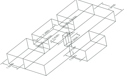
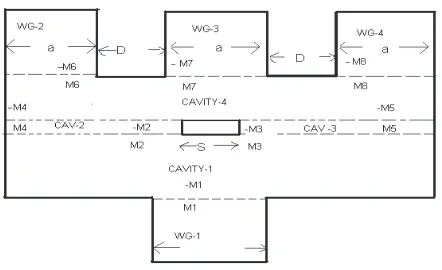
The diagram of a basic H-plane 1:3power divider is shown in Fig. 1 and with its cavity modeling and details of region in Fig. 2 which shows that the structure has 4 waveguide region and 4 cavity region. The interfacing apertures between different regions are replaced by equivalent magnetic current densities.
Figure 2. Cavity modeling and details of a basic 1:3power divider.
The magnetic field scattered inside the cavity region due to this source is determined by using cavity Green’s function of the electric vector potential. The cavity Green’s function has been derived by solving the Helmholtz equation for the electric vector potential for unit magnetic current source. The tangential components of the cavity scattered fields are derived in [5]. The final form of the tangential components of the cavity scattered field will be same as given in [6], except (a2, b2) will be replaced by (Lc, Wc) whereLcj is the length and
Wcj is the height of jth the cavity. Li and Wi are the half length and
half width ofith aperture. The cavity magnetic field, in general form, can be written as
Hxcavj(Mix) =−jωε k2 ∞ m=1 ∞ n=0
εmεnLiWi
2LcjWcj
k2−
mπ 2Lc 2 sin mπ 2Lcj
(x+Lcj)
×cos
nπ 2Wcj
(y+Wcj)
cos
nπ 2Wcj
(yw+Wcj) sinc nπ 2Wcj Wi
Fx(p)×
(−1) Γmnsin{2Γmntc}
cos{Γmn(z−tc)}cos{Γmn(z0+tc)} z > z0
cos{Γmn(z0−tc)}cos{Γmn(z+tc)} z < z0
While the general form of scattered field in the waveguide is given by Hxwvg(Eiy) =Hxwvg(Mix) =
−2LW
m
n
Ymne
Cmne mπ 2ai
2
+Ymnm
Cmnm nπ 2bi 2 × sin mπ 2ai
(x+ai)
cos
nπ 2bi
(y+bi)
cos
nπ 2bi
(yw+bi) sinc nπ 2bi W
kz kzη
εi =
1, i= 0 2, i= 0
Fx(p) =
cos
π 2
−mxw
ai
+p−m
sinc
πL 2
p L −
m ai
−cos
π 2
mxw
ai
+p+m
sinc
πL 2
p L+
m ai
At the region of the window, the tangential component of the magnetic field in the aperture should be identical and applying the proper boundary conditions at the aperture the electric fields can be evaluated [6].
3. SOLVING FOR THE ELECTRIC FIELD
To determine the electric field distribution at the window aperture, it is necessary to determine the basis function coefficients Ei,x/yp at
both the apertures. Since the each component of the field is described by M basis functions, 16M unknowns are to be determined from the boundary conditions. The Galerkin’s specialization of the method of moments [9] is used to obtain 16M-different equations from the boundary condition to enable determination of Epi,x/y. The weighting
functionwi,x/yq (x, y, z) is selected to be of the same form as the basis
function ei,x/yp . The weighting function and the moment of the field
are defined as follows:
wqi,y=
sin
qπ
2L(x−xw+L)
for xw−L≤x≤xw+L yw−W ≤y≤yw+W
wqi,x=
sin
qπ
2W (y−yw+W)
for xw−L≤x≤xw+L yw−W ≤y≤yw+W
0 elsewhere
The procedure for derivation of reflection and transmission coefficients is given in [12]. Following the same procedure the expressions for Γ and T is given by:
Γ = E
1 y +Ey2
Einc y
=−1−E11,y and
T21/31/41= E
transmitted y
Einc y
=−E12/3/4,y.
Figure 3. Comparison of theoretical, CST Microwave Studio simulated and measured data for an H-plane 1:3WR-90 waveguide power divider with 2t= 19.5 mm.
4. NUMERICAL RESULTS AND DISCUSSION
Theoretical data for the magnitude of scattering parameters for an H-plane 1:3WR-90 waveguide power divider at X-band has been compared with CST Microwave Studio simulated data in Fig. 3.
The theory has been validated by the excellent agreement with the theoretical, CST Microwave Studio simulated data and Measured Data. The scattering parameters for the circuit, when excited through port-2, port-3and port-4 have not been presented in this section because these are less important in the study of a power divider. ACKNOWLEDGMENT
array antenna,” 3rd International Conference on Microwave and Millimeter Wave Technology, 948–951, 2002.
4. Gardner, P. and B. H. Ong, “Mode matching design of three-way waveguide power dividers,” IEE Colloquium on Advances in Passive Microwave Components, 5/1–5/4, May 22, 1997.
5. Das, S. and A. Chakraborty, “A novel modeling technique to solve a class of rectangular waveguide based circuits and radiators,”
Progress In Electromagnetic Research, PIER 61, 231–252, MIT, USA, May 2006.
6. Das, S. and A. Chakrabarty, “Analysis of waveguide based power divider using multiple cavity modeling technique and performance improvement,”IRSI-2005, Bangalore, India, 2005.
7. Das, S., A. Chakrabarty, and A. Chakraborty, “Analysis of multiport waveguide power divider/combiner for phased array application,”NCC 2007, IIT Kanpur, India, 2007.
8. Eleftheriades, G., A. S. Omar, and L. P. B. Katehi, “Some important properties of waveguide junction generalized scattering matrices in the context of the mode matching technique,” IEEE
Transactions on Microwave Theory and Techniques, Vol. 42,
No. 10, 1896–1903, October 1994.
9. Harrington, R. F.,Field Computation by Moment Methods, Roger E. Krieger Publishing Company, USA, 1968.
10. Harrington, R. F., Time-Harmonic Electromagnetic Fields, McGraw-Hill Book Company, New York, 1961.