980 | P a g e
Modelling of Cascaded Multilevel STATCOM for Square
Wave-Controlled and Circulating current Compensasion
Rasal Priyanka W.
1, Prof. K.Chandra Obula Reddy
21,2
PG Student [EPS], Department Electrical Engineering, MSS’s CET,Jalna,Maharashtra, (India)
ABSTRACT
The proposed system implemented a FACTS device like STATCOM based cascaded multilevel converter is an
effective solution to compensate the circulating current and to control the square shaped waveform.
Simultaneously in order to maintain the voltage stability by compensating the circulating current in
transmission line. Cascaded multilevel based STATCOM can be placed at near the point of common coupling
for improving the power quality. This paper develops the mathematical model of cascaded multilevel based
STATCOM system in which voltage and current waveforms are simulated with the help of MATLAB /
SIMULINK. The good agreement between theoretical analysis and simulation results verify that the proposed
theoretical analysis method is valid and feasible, which can be extended to the analysis of similar power
electronic circuits. The analytical and simulation results show at the same condition, the voltage and current
harmonic contents of the dual three-level STATCOM can be effectively decreased compared with the three-level
STATCOM, and the capacity of the dual three-level STATCOM can be increased. Finally, the analytical results
obtained in this paper.
Keywords: Cascaded multilevel Static Synchronous Compensator (STATCOM), Circulating
current, H-Bridge stack cell, Square waveform.
I.INTRODUCTION
Power Quality (PQ) related concern is one of the most apprehensions now a days. The extensive use of
electronic equipment, such as information technology equipment, power electronics such as adjustable speed
drives (ASD), programmable logic controllers (PLC), energy-efficient lighting etc. led to a complete change of
electric loads nature. These loads are simultaneously the major causers and the major victims of power quality
problems. Due to the non-linear loads, mostly disturbances are occurred in power system as well as circulating
current also flowing from non linear load to source through transmission line. The circulating currents are
created by the mutual fluxes between the primary and secondary windings of the transformer as well as some
electromagnetic machines and which causes large amount of heating in conductor [1]. The circulating current
compulsorily depends upon the load. Generally there are three main regions in a power system and they are
generation, transmission and distribution. Out of them our focus is on the transmission system. Transmission
line interconnects one region to another region through conductor. Due to bilateral situation in the transmission
system i.e. same impedance of both systems from source to load or vice versa. Transmission conductors act like
981 | P a g e
we can’t change the conductor also. So to change this effect we have to implement one of the techniques. The
proposed technique cascaded multilevel H-Bridge STATCM is shown in fig.1. As an industry customer of
electric power, an electrical arc furnace (EAF) is a major flicker source that causes major power quality
problems. For a 40-MVA EAF in Tennessee, USA, a cascade-multilevel converter (CMC)-based Static
Synchronous Compensator (STATCOM) with high bandwidth is proposed for EAF flicker mitigation[2]. A
modular and decoupled approach to achieve harmonic cancellation in a multilevel Static Compensator
(STATCOM) is presented in [3].
Fig.1Basic block diagram of proposed system
II. OPERATING PRINCIPLE OF CASCADED MULTILEVEL CONVERTER BASED
STATCOM
The STATCOM is connected to the problematic bus of a power network at a PCC. To make the entire system
work efficiently and accurately, the controller requirements to be strong. All necessary voltages and currents
are measured and then fed into the controller to be compared with the commands. The controller then performs
feedback control, and outputs a set of switching signals to drive the main valves of the power converter
accordingly. The feedback controller regulates the output currents and DC-link voltages. The single-line
diagram of the STATCOM system is illustrated in Figure 2. In general, the CMC is represented by an ideal
VSC, which is associated with internal loss, that is connected to the AC power by means of coupling
impedances. Generally, the internal losses are accumulated from semiconductor switching and conduction
losses, stray resistance losses in interconnections and passive components, snubber circuit losses, etc.
Fig.2 Single-line diagram of the cascaded-multilevel converter-based STATCOM
The exchange of real power and reactive power between the cascaded converter and the power system can be
controlled by adjusting the amplitude and displacement angle of the converter output voltages with respect to
the voltage at the PCC. In the case of a lossless converter, the output voltage of the converter is controlled to be
982 | P a g e
reactive power to the connected network, while, in the inductive mode, the STATCOM absorbs a given amount
of reactive power from the connected network. To operate the STATCOM in capacitive mode, +Q, the
magnitude of the converter output voltage is controlled to be greater than that of the power system. On the other
hand, the output-voltage magnitude of the converter is controlled to be less than that of the power system in
order to operate the STATCOM in inductive mode, -Q. However, in practice, a converter is associated with
internal losses. As a result, without any control, the capacitor voltage will decrease and will eventually collapse.
To regulate the capacitor voltage, a small phase shift δ is introduced between the converter voltage and the
power system voltage.
A schematic of a CMC-based STATCOM is shown in Figure 3. Basically, the STATCOM system is composed
of three main parts: a multilevel-cascaded VSC with separated DC capacitors, the coupling inductors, and a
controller. A coupling inductor in each phase serves as both a converter output-current filter and a reactive
power coupler. The main purpose of the coupling inductors is to filter out current harmonic components that are
mainly caused by the modulation techniques used in the converters. In a very-high-voltage system, above 13.8
kV, the leakage inductances of coupling step-up power transformers can function as coupling reactors. A
multilevel-cascaded converter consists of a number of identical H-bridge converters, whose output terminals are
connected in series. The output voltage is thus the summation of those H-bridge converters, i.e.,
Vkn =Vk1+Vk2+ +VkN
where k is the phase notation, i.e., a, b or c, and N is the number of H-bridge converters per phase.
Since three output voltage levels can be synthesized by an H-bridge converter, the total number of output-phase
voltage levels, as shown in Figure 4, equals 2N+1. The maximum number of line-to-line voltage levels is 4N+1.
By increasing the number of H-bridge converters, the output-voltage THD is significantly improved. The
output-voltage waveform approaches sinusoidal when the number of H-bridge converters reaches infinity.
Moreover, the power capacity of the system is increased, and the dynamic response is improved. The number of
H-bridge converters is, however, limited by numerous practical concerns. The most important one is the
complexity of the control system. A greater number of voltage levels introduces the DC-link-imbalance
problems, and of course increases the system cost
.
983 | P a g e
Fig.4 Phase-voltage waveform of the cascaded-multilevel converterIII. INTRODUCTION OF PROPOSED STATCOM
The selected test STATCOM, which contains a cascaded (chain-circuit) multilevel converter and its connection
to the ac system, is shown in Figure 5. The multilevel STATCOM system includes a three-phase transformer
and three strings of single cells that are connected in series. A single cell here is a full-bridge, single-phase
inverter with a capacitor as the dc source. Note that only chain circuit. A with its insulated- gate bipolar
transistors (IGBTs), diodes, and capacitors is shown, but similar groups of single cells are also connected in
branches B and C.
The STATCOM parameters that determine the main circuit are the number of cells per phase X dc capacitances
CDC1 to CDCX, buffer inductance LDC transformer leakage inductance and transformer ratio . The relationship
between the number of single cells per string and the number of levels for a cascaded multilevel converter is
given by X=(N-1)/2. It is assumed that all capacitances are equal and that the steady-state voltages across these
capacitors are also identical (with the help of a suitable controller). To ensure low converter losses and dc
voltage ripple, the STATCOM system parameters are optimized. The ratio between XAC (w* LAC) and RAC is
assumed to be constant XAC / RAC = 10. The converter switching losses are reduced by the use of ―square wave
control‖ where each device has only one turn-on and turn-off per cycle. The harmonic distortion is reduced by
calculating the firing angle at each cell to cancel one harmonic. In view of the fact that triplen harmonics are
cancelled in the converter delta connection, the firing angles for the individual cells are calculated for
cancellation of the lowest odd, non triple harmonics, and their values are shown for selected test systems. These
calculated firing angles can cancel only steady-state harmonics but as loading changes, harmonics increase.
984 | P a g e
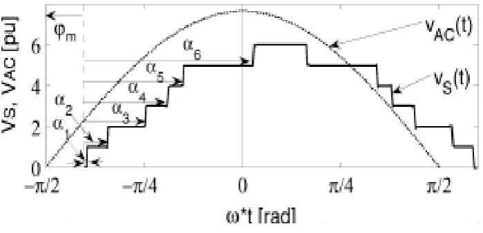
The ideal stepped output voltage of a 13-level converter is shown in Figure 6. The STATCOM uses indirect
control, as shown in Figure5. This control has, as a benefit, a constant modulation ratio, resulting in constant
control angles and, therefore, in low harmonics even at low converter voltages. The dc voltage is affected by
controlling the angle (i.e., the active power transfer). The phaser diagram of the STATCOM system is shown in
Figure 7. It is assumed that the system is balanced and all variables are represented with a fundamental
frequency phaser. All ac voltages are shown as line-neutral magnitudes. The STATCOM parameters that
determine the main circuit are the number of cells per phase X dc capacitances CDC1 to CDCX, buffer inductance
LDC transformer leakage inductance and transformer ratio . The relationship between the number of single cells
per string and the number of levels for a cascaded multilevel converter is given by X=(N-1)/2. It is assumed that
all capacitances are equal and that the steady-state voltages across these capacitors are also identical (with the
help of a suitable controller). To ensure low converter losses and dc voltage ripple, the STATCOM system
parameters are optimized. The ratio between XAC (w* LAC) and RAC is assumed to be constant XAC / RAC = 10.
The converter switching losses are reduced by the use of ―square wave control‖ where each device has only one
turn-on and turn-off per cycle. The harmonic distortion is reduced by calculating the firing angle at each cell to
cancel one harmonic. In view of the fact that triplen harmonics are cancelled in the converter delta connection,
the firing angles for the individual cells are calculated for cancellation of the lowest odd, non triple harmonics,
and their values are shown for selected test systems. These calculated firing angles can cancel only steady-state
harmonics but as loading changes, harmonics increase . The ideal stepped output voltage of a 13-level converter
is shown in Figure 6. The STATCOM uses indirect control, as shown in Figure5. This control has, as a benefit,
a constant modulation ratio, resulting in constant control angles and, therefore, in low harmonics even at low
converter voltages. The dc voltage is affected by controlling the angle (i.e., the active power transfer). The
phaser diagram of the STATCOM system is shown in Fig7. It is assumed that the system is balanced and all
variables are represented with a fundamental frequency phaser. All ac voltages are shown as line-neutral
magnitudes.
985 | P a g e
Fig.7 STATCOM phaser diagram where the general reference frame is linked with VAC
IV. CONTROL STRATEGY
This section proposes a development procedure for the model and feedback control of a CMC-based
STATCOM. Figure 8 illustrates the block diagram, showing the relationship between the modelling and
feedback-control design. Although this methodology focuses on STATCOM applications, it can be employed
elsewhere. The process begins with model development. The results of this step are key transfer functions of the
control parameters to state variables such as STATCOM currents and DC capacitor voltages. As will be
proposed in Chapter 5, the feedback control is designed and evaluated based on the derived transfer functions.
Because of the proposed modelling method, the stability of the feedback loops can be systematically evaluated.
The loop gains are then modified to achieve as much stability as possible, while the dynamic response is not
sacrificed. The proposed control technique is validated by both computer simulation and experiments.
Fig.8 Control development for the cascaded-multilevel converter-based STATCOM
V. SIMULATION RESULTS
The performances of MMC based STATCOM are evaluated by computer simulation using
986 | P a g e
Fig.9 Source Voltage waveform
Fig.10 THD of source side
Figure 9 shows the input waveform for source voltage versus time in which there is no positive amplitude
present in phase Y & B due to circulating current. Some voltage sag occurs in it. The respective Total Harmonic
Distortion present in source side is 40.44 % without injecting the current. This is shown in figure10.
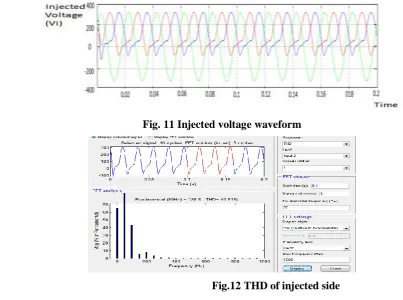
Fig. 11 Injected voltage waveform
987 | P a g e
To overcome this problem we have inject the current into the system by Cascaded Multi level Converter Based
STATCOM i.e. Stack Cell. Figure 11 shows the injected waveform for injected voltage versus time such that
there is no negative amplitude in phase Y & B. The respective Total Harmonic Distortion present in injected
side is 44.51 % without injecting the current. This is shown in figure12.
Fig.13 Load current waveform
Fig.14 THD of load side
Figure 13 shows the output waveform for load current versus time in which pure sinusoidal waveform is
obtained. The respective Total Harmonic Distortion for load side is 0 % as shown in figure 14.
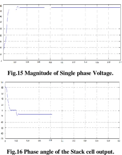
Fig.15 Magnitude of Single phase Voltage.
Fig.16 Phase angle of the Stack cell output.
Figure 15 shows the magnitude of 1 phase output voltage of Stack Cell which are 1800 electrical apart. Some of
988 | P a g e
i.e. above 1200 phase angle. So the phase angle is -200 which is shown in figure 16.So the magnitude & phase
angle of injected voltage will be working together to maintain the power quality.
VI. CONCLUSION
A suitable and accurate analytical model of an indirectly controlled cascaded multilevel STATCOM with
square-wave control is presented in this paper. The converter voltage Components are analyzed in detail for a
single-cell and the results are then generalized for a multilevel cascaded converter. The converter ac voltage
waveform is of a nonlinear, discrete, and dynamic nature, which is described mathematically by appropriate
averaged expressions. The dynamic, analytical state-space model is built of subsystems to enable model
application to a wide range of system configurations and various dynamic studies. The developed STATCOM
model is linearized and implemented in MATLAB. Eigen value studies are conducted for each particular test
system in order to select optimum open-loop controller gains.
VII. FUTURE SCOPE
Although this paper has covered most of the interesting issues and challenges of the CMC-based STATCOM,
additional work has been left for future research. The first part is the coordination between the proposed internal
and external controls. From the standpoint of external control design, the internal control, which is the
combination of the decoupling power control technique and the cascaded PWM, can be modeled as a black box
in which high-quality output voltage-current waveforms and relatively fast dynamic responses are embedded.
With an effective external control design, a high-performance, stable, reliable CMC-based STATCOM system
can be completely achieved. The second part is the fault-protection study for the CMC-based STATCOM. Due
to the excessive number of semiconductor devices and passive components, how to design a fault protection
scheme to enhance the ride-though capability in various fault scenarios remains as an important challenge.
Finally, the last part is the redundancy of the CMC-based STATCOM system. Due to the identical HBBBs used
in the CMC, the N+1 rule may be applied, where N is the number of HBBBs per phase.
REFERENCES
[1] A Review of Power Quality Problems & Solutions in Electrical Power System. R.K. Rojin, ME Student,
department of EEE, Maria College of Engineering & Technology, Attoor, Tamilnadu, India.
[2] Evaluation of Cascaded Multilevel STATCOM for Arc Furnace Flicker Mitigation Chong Han, Member,
IEEE, Zhanoning Yang, Bin Chen, Alex Q. Huang, Fellow, IEEE, Bin Zhang, Student Member, IEEE,
Michael R. Ingram, Senior Member, IEEE, and Abdel-Aty Edris, Senior Member, IEEE.
[3] Decoupled and Modular Harmonic Compensation for Multilevel STATCOM Javier A. Muñoz, Member,
IEEE, José R. Espinoza, Member, IEEE, Carlos R. Baier, Member, IEEE, Luis A. Morán, Fellow, IEEE,
Johan I. Guzmán, Member, IEEE, Víctor M. Cárdenas, Member, IEEE.
[4] G. Joos, X. Huang, and B.-T. Ooi, ―Direct-coupled multilevel cascaded series var compensators,‖ IEEE
989 | P a g e
[5] R. Betz, B. Cook, T. Summers, R. Palmer, A. Bastiani, S. Shao, and K. Willis, ―Design and development of
an 11 kV H-bridge multilevel STATCOM,‖ presented at the Australasian Univ. Power Eng. Conf., Perth,
Western Australia, Dec. 2007
[6] Hochgraf, R. Lasseter, D. Divan, and T. A. Lipo, ―Comparison of multilevel inverters for static var compensation,‖ in Proc. Conf. Rec. Ind. Appl. Soc. Annu. Meeting, Denver, CO, 1994, vol. 2, pp. 921–928.
[7] J. S. Lai and F. Z. Peng, ―Multilevel converter—A new breed of power converter,‖ IEEE Trans. Ind. Appl.,
vol. 32, no. 3, pp. 509–517, May 1996.
[8] F. Z. Peng, J. W. McKeever, and D. J. Adams, ―A power line conditioner using cascade multilevel inverters for distribution systems,‖ IEEE Trans. Ind. Appl., vol. 34, no. 6, pp. 1293–1298, Nov. 1998
[9] S. Sirisukprasert, J. S. Lai, and T. H. Liu, ―Optimum harmonic reduction with a wide range of modulation
indexes for multilevel converters,‖ IEEE Trans. Ind. Electron., vol. 49, no. 4, pp. 875–881, Aug. 2002.
[10] J. D. Ainsworth, M. Davies, P. J. Fitz, K. E. Owen, and D. R. Trainer,―Staticvar Compensator
(STATCOM) based on single-phase circuit converters,‖ Proc. Inst. Elect. Eng., Gen. Transm. Distrib., vol.
145, no. 4, pp. 381–386, Jul. 1998..
[11] D. Soto and R. Pena, ―Nonlinear control strategies for cascaded multilevel STATCOMs,‖ IEEE Trans.
Power Del., vol. 19, no. 4, pp. 1919–1927, Oct. 2004.
[12] R. Sternberger and D. Jovcic, ―Small signal multi-level STATCOM model,‖ presented at the Power Eng.
Soc. Gen. Meeting, Montreal, QC, Canada, Jun. 2006.
[13] ―PSCAD/EMTDC 4.1 Users Manual,‖ Manitoba HVDC Research Center, 2004, Tutorial manual.
[14] D. Jovcic, N. Pahalawaththa, M. Zavahir, and H. Hassan, ―SVC dynamic analytical model,‖ IEEE Trans.
Power Del., vol. 18, no. 4, pp. 1455–1461, Oct. 2003.
[15] A. Yazdani and R. Iravani, ―An accurate model for the DC-side voltage control of the neutral point diode clamped converter,‖ IEEE Trans. Power Del., vol. 21, no. 1, pp. 185–193, Jan. 2006.
[16] M. Mohaddes, A. M. Gole, and S. Elez, ―Steady-state frequency response of STATCOM,‖ IEEE Trans.
Power Del., vol. 16, no. 1, pp. 18–23, Jan. 2001.
[17] D. Jovcic and R. Sternberger, ―Frequency domain analytical model for a cascaded multi-level STATCOM,‖
IEEE Trans. Power Del., vol. 23, no. 4, pp. 2139–2147, Oct. 2008.
[18] N. G. Hingorani and L. Gyugyi, Understanding FACTS: Concepts and Technology of Flexible AC
Transmission Systems. Piscataway, NJ: IEEE, 2000.
[19] R. Sternberger and D. Jovcic, ―Theoretical framework for minimizing converter losses and harmonics in a
multi-level STATCOM,‖ IEEE Trans. Power Del., vol. 23, no. 4, pp. 2376–2384, Oct. 2008.
[20] Y. Li and B. Fu, ―A novel DC voltage detection technique in the CHB inverter-based STATCOM,‖ IEEE
Trans. Power Del., vol. 23, no. 3, pp. 2139–2147, Jul. 2008.
[21] D. Jovcic and G. P. Pillai, ―Discrete system model of a six-pulse SVC,‖ in Proc. Conf. IASTED EuroPES,