A Vision-based South African Sign Language Tutor
by
Hendrik Adrianus Cornelis de Villiers
Dissertation presented for the degree of Doctor of Philosophy in
the Faculty of Engineering at Stellenbosch University
Promoters:
Prof. T. R. Niesler Prof. L. van Zijl
Declaration
By submitting this dissertation electronically, I declare that the entirety of the work contained therein is my own, original work, that I am the sole author thereof (save to the extent explicitly otherwise stated), that reproduction and publication thereof by Stellenbosch University will not infringe any third party rights and that I have not previously in its entirety or in part submitted it for obtaining any qualification.
April 2014
Date: . . . .
Copyright © 2014 Stellenbosch University All rights reserved.
Abstract
A Vision-based South African Sign Language Tutor
H. A. C. de Villiers Dissertation: PhD
April 2014
A sign language tutoring system capable of generating detailed context-sensitive feedback to the user is presented in this dissertation. This stands in contrast with existing sign language tutor systems, which lack the capability of providing such feedback.
A domain specific language is used to describe the constraints placed on the user’s move-ments during the course of a sign, allowing complex constraints to be built through the com-bination of simpler constraints. This same linguistic description is then used to evaluate the user’s movements, and to generate corrective natural language feedback. The feedback is dy-namically tailored to the user’s attempt, and automatically targets that correction which would require the least effort on the part of the user. Furthermore, a procedure is introduced which allows feedback to take the form of a simple to-do list, despite the potential complexity of the logical constraints describing the sign. The system is demonstrated using real video sequences of South African Sign Language signs, exploring the different kinds of advice the system can produce, as well as the accuracy of the comments produced.
To provide input for the tutor system, the user wears a pair of coloured gloves, and a video of their attempt is recorded. A vision-based hand pose estimation system is proposed which uses the Earth Mover’s Distance to obtain hand pose estimates from images of the user’s hands. A two-tier search strategy is employed, first obtaining nearest neighbours using a simple, but related, metric. It is demonstrated that the two-tier system’s accuracy approaches that of a global search using only the Earth Mover’s Distance, yet requires only a fraction of the time. The system is shown to outperform a closely related system on a set of 500 real images of gloved hands.
Uittreksel
’n Visie-gebaseerde Suid-Afrikaanse Gebaretaaltutor
(“A Vision-based South African Sign Language Tutor”) H. A. C. de Villiers
Proefskrif: PhD April 2014
’n Gebaretaaltutorstelsel met die vermo¨e om konteks-sensitiewe terugvoer te lewer aan die ge-bruiker word uiteengesit in hierdie proefskrif. Hierdie staan in kontras met bestaande tutorstel-sels, wat nie hierdie kan bied vir die gebruiker nie.
’n Domein-spesifieke taal word gebruik om beperkinge te definieer op die gebruiker se be-wegings deur die loop van ’n gebaar. Komplekse beperkinge kan opgebou word uit eenvoudiger beperkinge. Dieselfde linguistieke beskrywing van die gebaar word gebruik om die gebruiker se bewegings te evalueer, en om korrektiewe terugvoer te genereer in teksvorm. Die terugvoer word dinamies aangepas met betrekking tot die gebruiker se probeerslag, en bepaal outomaties die maklikste manier wat die gebruiker sy/haar fout kan korrigeer. ’n Prosedure word uiteen-gesit om die terugvoer in ’n eenvoudige lysvorm aan te bied, ongeag die kompleksiteit van die linguistieke beskrywing van die gebaar. Die stelsel word gedemonstreer aan die hand van op-names van gebare uit Suid-Afrikaanse Gebaretaal. Die verskeie tipes terugvoer wat die stelsel kan lewer, asook die akkuraatheid van hierdie terugvoer, word ondersoek.
Om vir die tutorstelsel intree te bied, dra die gebruiker ’n stel gekleurde handskoene. ’n Visie-gebaseerde handvormafskattingstelsel wat gebruik maak van die Aardverskuiwersafstand (Earth Mover’s Distance) word voorgestel. ’n Twee-vlak soekstrategie word gebruik. ’n Rowwe afstandsmate word gebruik om ’n stel voorlopige handpostuurkandidate te verkry, waarna die stel verfyn word deur gebruik van die Aardverskuiwersafstand. Dit word gewys dat hierdie benaderde strategie se akkuraatheid grens aan die van eksakte soektogte, maar neem slegs ’n fraksie van die tyd. Toetsing op ’n stel van 500 re¨ele beelde, wys dat hierdie stelsel beter presteer as ’n naverwante stelsel uit die literatuur.
Acknowledgements
I would like to express my sincere gratitude to the following people and organisations:
• The Wilhelm Frank Trust, Telkom SA and the National Research Foundation of South Africa (grant UID 71926) for their financial support of this research.
• The High Performance Computing facility at Stellenbosch University, which was utilised to perform the experimental evaluation of the hand pose estimation system.
• SLED (http://www.sled.org.za) for the sign language classes they offer, which pro-vided valuable insight into the performance requirements of the hand pose estimation system, and whose educational materials served as an invaluable resource for the sign definitions used in the proof of concept system (Note: SLED is not associated with our group and were not involved in the research process)
• My test subjects, for long hours spent in front of the camera.
• My supervisors Prof. Thomas Niesler and Prof. Lynette van Zijl, thank you for your unswerving support, encouragement and guidance.
• Viola Lengner, who still keeps me on track. • My family, for all your support.
• All of my friends, for your excellent company and keeping me in high spirits.
• My partner Halford, for endless enthusiasm, love and support, without which this would scarcely have been possible.
Dedication
For Halford
Contents
Declaration i Abstract ii Uittreksel iii Acknowledgements iv Dedication v Contents vi List of Figures xList of Tables xii
Nomenclature xiii
1 Introduction 1
I Hand Pose Estimation
4
2 Introduction to Hand Pose Estimation 5
2.1 Pose estimation through database search . . . 6
2.2 The Earth Mover’s Distance . . . 7
2.3 Overview . . . 7
3 Survey of Hand Pose Estimation Methods 9 3.1 Introduction . . . 9
3.2 Single frame pose estimation systems . . . 10
3.3 Database driven pose estimation systems . . . 12
3.4 Candidate parameter sets . . . 13
3.5 Synthetic model . . . 14
3.6 Feature extraction . . . 15
CONTENTS vii
3.7 Database index generation and lookup . . . 15
3.8 Conclusion . . . 19
4 Similarity Search in Metric Spaces 21 4.1 Similarity search in databases . . . 22
4.2 The Earth Mover’s Distance . . . 24
4.3 Summary . . . 28 5 Experimental Setup 29 5.1 Hand model . . . 29 5.2 Image registration . . . 30 5.3 Search structures . . . 32 5.4 Summary . . . 33 6 Experimental Evaluation 34 6.1 Test set . . . 34
6.2 Nature of tests performed . . . 35
6.3 Discussion . . . 39
6.4 Summary . . . 42
7 Automatic Colour Calibration 43 7.1 Hand detection . . . 44
7.2 Graphical model overview . . . 48
7.3 Notation . . . 50
7.4 Colour models . . . 51
7.5 Cluster graphs . . . 53
7.6 Model variables . . . 56
7.7 Joint distribution factorisation . . . 56
7.8 Model potentials . . . 60
7.9 Calibration cluster graph . . . 60
7.10 Message passing . . . 64
7.11 Results . . . 65
7.12 Conclusion . . . 65
8 Hand Tracking in Video Sequences 68 8.1 Rough hand tracking . . . 68
8.2 Single-frame pose estimation . . . 71
8.3 Multi-frame pose estimation . . . 72
8.4 Summary . . . 72
CONTENTS viii
9.1 Pose estimation . . . 74
9.2 Automatic colour calibration . . . 76
9.3 Prelude . . . 77
II Sign Language Tutor
78
10 Introduction to Sign Language Processing 79 10.1 South African Sign Language . . . 7910.2 Gesture and sign language recognition . . . 80
10.3 Existing sign language tutors . . . 86
10.4 Discussion . . . 89
11 Features and Constraints 91 11.1 Features . . . 91
11.2 Atomic constraints . . . 93
11.3 Compound constraints . . . 95
11.4 Constraint types . . . 97
11.5 Summary . . . 97
12 Single-frame Advice Generation 98 12.1 Not-propagation . . . 99 12.2 Or-pruning . . . 100 12.3 And-prioritisation . . . 102 12.4 Suggested features . . . 103 12.5 Feature representation . . . 106 12.6 Summary . . . 109 13 Video-level Advice 111 13.1 Sign specification . . . 111 13.2 Sign segmentation . . . 113
13.3 Frame selection and advice generation . . . 115
13.4 Additional language constructs . . . 116
13.5 Summary . . . 117 14 Experimental Evaluation 120 14.1 Data collection . . . 120 14.2 Methods . . . 121 14.3 Results . . . 122 14.4 Discussion . . . 125 14.5 Summary . . . 127
CONTENTS ix
15 Summary and Conclusion for the Sign Language Tutor 128
IIIConclusion and Future Work
132
16 Overall Conclusion and Future Work 133
16.1 Review of conducted work . . . 133 16.2 Future work and concluding remarks . . . 135
Appendices 138
A Proof: The compound EMD is a metric 139
B Signs and Constraints 141
B.1 List of constraints . . . 141 B.2 Sign definitions . . . 144
List of Figures
2.1 Pose estimation system structure, indicating offline and online components. . . 6
3.1 Features employed by systems discussed in Chapter 3. . . 14
3.2 Illustration of the Hausdorff distance. . . 16
3.3 Illustration of the chamfer distance. . . 17
3.4 L1embedding of the EMD due to Indyk and Thaper [38]. . . 18
4.1 Conceptual view of ball partitioning. . . 23
4.2 Visualisation of the object-pivot distance constraint. . . 24
4.3 Example of an EMD match between two signatures. . . 25
4.4 A hypothetical contour matching example. . . 26
4.5 Example of an EMD signature extracted from a synthetic image. . . 27
4.6 Contrastive examples of the asymmetric chamfer distance and the EMD. . . 28
5.1 The glove worn by the user and the 3D model used to approximate it in generating the synthetic database. . . 30
5.2 Example pose rendered from all viewpoints represented in the database and masks for each case normalised for scale and rotation. . . 30
5.3 Image processing of test set images. . . 31
5.4 The procedure used to obtain the image-plane rotation of the hand. . . 32
6.1 Sample image from test set . . . 34
6.2 Example nearest neighbour results for different search techniques superimposed on input images. . . 36
6.2 Example nearest neighbour results for different search techniques superimposed on input images(cont.) . . . 37
6.3 Comparison of idealised performance of multiple hypothesis tracking, excluding two-tier approach. . . 39
6.4 Comparison of idealised performance of multiple hypothesis tracking, including two-tier approach. . . 40
7.1 Calibration image example. . . 44
7.2 The hue-saturation plane. . . 45
LIST OF FIGURES xi
7.3 Rough prior colour models used in colour calibration and resulting likelihood images. 46
7.4 Locating the hand during colour calibration. . . 47
7.5 Simplified illustration of the autocalibration graphical model. . . 48
7.6 Examples of spatial priors. . . 49
7.7 The prior colour models at the start of the inference process. . . 50
7.8 Colour models and the effect of their parameters. . . 52
7.9 Example of a cluster graph. . . 54
7.10 Chain graph capturing conditional independencies within the colour calibration model. . . 57
7.11 Clusters modelling each pixel in the calibration image. . . 60
7.12 Clusters modelling constraints between neighbouring pixels. . . 61
7.13 Idealised colour model cluster connections to pixels. . . 62
7.14 Distributed representation of a colour model as a quad tree. All clusters haveWmas their sole cluster variable. . . 63
7.15 Topology of the colour model tree connections. . . 64
7.16 Evolution of marker beliefs during inference. . . 66
7.17 Comparison of prior and posterior colour models. . . 67
8.1 Segmenting an image and identifying hand regions. . . 69
11.1 The three intervals for the SASL sign for “woman”. . . 91
11.2 Illustration of positional features and associated membership function. . . 92
11.3 Example of compound constraints obtained from different logical connectives. . . . 95
12.1 The basic logical connectives and their corresponding representations as elementary constraint trees. . . 99
12.2 Running example for not-propagation, or-pruning and and-prioritisation . . . 99
12.3 Basic example of or-pruning. . . 100
12.4 Preventing contradictions due to or-pruning. . . 101
12.5 Already satisfied constraints may still need advice. . . 103
13.1 Domain specific language definition of the SASL sign “woman”. . . 112
13.2 Segmentation scores for an attempt of the sign “woman”. . . 114
List of Tables
6.1 Average fingertip position error (∆p) and average viewpoint error (∆φ) compared
with ground truth for nearest neighbour. . . 38
6.2 Average fingertip position error per finger compared with ground truth for nearest neighbour. . . 38
7.1 Table of colour model parameters . . . 53
11.1 Examples of constraints defined in the system. . . 97
14.1 Experimental results from tutor. . . 123
14.2 Experimental results from tutor(cont.) . . . 124
14.3 All actively violated constraints tested during the experimental evaluation. . . 125
B.1 All constraints defined in the system. . . 142
B.1 All constraints defined in the system(cont.) . . . 143
Nomenclature
AbbreviationsEMD Earth Mover’s Distance HMM Hidden Markov Model SASL South African Sign Language
Features
¯
x Input features ˜
x Feature constraint variables ˆ
x Suggested features
Constraints
cn Constraint
sn(x) Satisfaction function
cn↔sn(x) The constraintcnhas satisfaction functionsn(x) Metrics
d A dissimilarity measure or the compound EMD
d∗ Areas-and-means distance measure
dSC Symmetric chamfer distance
dAC Asymmetric chamfer distance
dEMD Earth Mover’s Distance
Chapter 1
Introduction
Existing sign language tutors lack the ability to generate context-sensitive advice based on the many complex constraints a signer must satisfy during the phases of a sign. In this work, a context-sensitive advice generation system for a South African Sign Language (SASL) tutor is presented.
Typically, sign language tutors show the user the correct signing of a word, and the user is then asked to attempt the sign. The tutor must then monitor the user’s movements, comment on the correctness of the signing and provide advice to the user. It is in particularly this last phase where existing tutors are lacking. It is here that context-sensitive advice would be most useful. Such advice should:
• be specifically tailored to the user’s current attempt;
• take into account the easiest way that the user can correct their mistake, given their current attempt;
• take into account the exact constraints on the user’s movements during any particular phase of a sign;
In addition, it is desirable that the advice expresses the available information in a form that the user can easily understand and is not self-contradictory. Furthermore, the system must allow easy extension by allowing the addition of new constraints and new modes of providing feedback such as natural language feedback, diagrams or animations.
It is the current lack of a satisfactory solution to this problem that this dissertation seeks to address, and it will be demonstrated that these requirements can be met simultaneously.
The system is vision-based, as a computing device with a video camera is possibly the lowest common denominator that can serve as a target for development. This necessitates a subsystem which can accurately track the relevant portions of the user’s movements. While the user’s hands are by no means the only important aspect during signing, hand pose estimation is one of the most challenging subdisciplines of human pose estimation, due to the variability in hand shape and orientation in sign languages. Movements of interest are rapid, yet subtle.
CHAPTER 1. INTRODUCTION 2
These complexities are compounded by the requirements imposed by a tutor system. While it is possible to perform sign languagerecognitionusing features that do not include any detailed reconstruction of the hand pose, a tutor system is tasked with providing advice given a sign that is known a priori. As such, the problem is one of producing commentary and advice, and not one of recognition. Therefore, a more detailed reconstruction of the hand pose must be attempted. As there is also an expectation that the sign will be performed incorrectly (at least initially), the system must leave open the possibility of hand positions, orientations and shapes that are far from correct. This implies that an estimation of the current hand pose is needed that cannot rely on prior pose information.
There exists a class of hand pose estimation systems that make use of nearest neighbour search to find a set of candidate poses without using prior information. However, the similar-ity measure defining “nearness” varies greatly between systems. A similarsimilar-ity metric that has shown considerable promise in recent years is the Earth Mover’s Distance (EMD). The EMD is, however, relatively expensive to calculate, and so any practical system employing it must use it sparingly. The hand pose estimation system presented in Part I utilises the EMD, but addresses the concerns surrounding its computational complexity by using it only in the last stage of the hand pose estimation process.
The key contributions stemming from the work presented in this dissertation can now be listed. The following are addressed in Part I, which describes the hand pose estimation compo-nent of the system.
• A system is presented which avoids excessive reliance on the EMD by means of a two-tier search. First, initial searches for candidates are performed with a related but easily com-puted approximate metric. Then, the EMD is used to refine this initial set of candidates. • The system is tested on a set of 500 real images of gloved hands. It is confirmed that the
two-tier system’s performance approaches that of a system which directly uses the EMD for all distance calculations, while offering a large reduction in computational complexity. The accuracy of the system is compared to a closely related existing system, and found to improve upon it.
• An automatic colour calibration procedure utilising a graphical model is proposed, and it is demonstrated that this procedure is able to provide accurate colour model estimates based on rough prior knowledge of the colour models, and a calibration image within which the user assumes a known hand pose.
Part II of the dissertation describes the tutor component of the system, and addresses the following.
• A domain-specific language is defined which allows the description of sign language signs by defining the constraints on the user’s movement during each phase of a sign. The language allows complex constraints to be built from atomic constraints using a variety
CHAPTER 1. INTRODUCTION 3
of logical connectives such as ‘and’, ‘or’ and ‘not’. The language can be easily extended by defining new atomic constraints.
• An advice generation system is presented that uses the linguistic description of the sign to generate context-sensitive feedback aimed at correcting the user’s attempt. The system takes into account the relevant aspects of the user’s current attempt, minimises the effort needed on the part of the user to correct their mistake, and targets a set of suggested features which satisfies all the constraints on the user’s movement.
• A procedure is presented which allows the potentially complex logical structure of the constraints placed on the user’s movement to be simplified into a simple to-do list of advice which the user may more readily understand, yet does not discard relevant in-formation. This procedure also eliminates potential sources of paradoxical advice, and ensures that constraints may generate advice independent of each other.
• The advice generation system leaves open the exact mode of feedback given to the user. Possible modes of feedback include natural language feedback, diagrams or animations (natural language feedback is employed for purposes of demonstration).
• The system is evaluated using real video sequences obtained for six South African Sign Language signs. The system behaviour is explored for a variety of constraint types, and results are presented regarding the types and quality of the advice produced by the system. Publications stemming from this work include De Villiers et al. [26] (under review), which presents the tutor system, and De Villiers et al. [24] (published), which discusses the hand pose estimation system.
The remainder of the dissertation will be presented in three parts. The first part presents the hand pose estimation system, the second describes the tutor component of the system, and the final part draws conclusions from the results obtained in the previous two parts, and explores potential avenues for future research.
Part I
Hand Pose Estimation
Chapter 2
Introduction to Hand Pose Estimation
Hand position, velocity, orientation and shape are core elements used to convey meaning in sign languages. Information about the state of the hands is thus key to any natural language processing system for signed languages.
Certain systems collect hand information by using data gloves [58]. In these cases, extract-ing information about the hand pose is especially simple. Additional sensors can be used to obtain information about hand orientation and position (and thus velocity). While attractive in terms of the state information they can provide, data gloves are expensive, and are a relatively rare commodity.
In addition, no information about non-manual gestures can be obtained using data gloves, and so some other means of gathering such data is needed, further increasing costs.
In contrast, vision-based hand pose estimation systems make use of camera hardware, which is now ubiquitous, and the price of quality hardware continues to fall as technology advances. Apart from hand pose estimation, non-manual gestures may also be tracked using video hard-ware, and so no extra investment in equipment is necessary.
However, hand pose estimation from video sequences is non-trivial. While tracking the position and the velocity of the hand are relatively easy, estimating the orientation and shape of the hand is more challenging. There are several reasons for the complexity of hand pose estimation. The hand has a large number of degrees of freedom, and so the state space that needs to be explored is large. In addition, this makes it challenging to collect a significant quantity of training data for machine learning approaches to hand pose estimation.
When the task of interest is sign language recognition, it is often not necessary to attempt an accurate reconstruction of the hand state. Features which encapsulate the appearance of the hand, rather than its pose, may easily be rich enough to choose between the discrete possibilities present in different signs.
Sign language tutors, however, must comment on the shape of the hand, and provide advice regarding it when necessary. This implies that some detailed reconstruction of the hand pose must be attempted.
Yet, at the same time, processing sign language represents a particularly challenging
CHAPTER 2. INTRODUCTION TO HAND POSE ESTIMATION 6
Candidate Parameter Sets
Rendered Candidates Database Generation Image Acquisition Feature Extraction Database Lookup Pose Candidates Offline Online
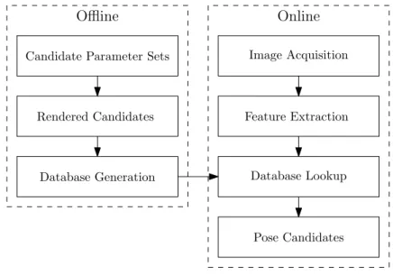
Figure 2.1:Pose estimation system structure, indicating offline and online components.
main of gesture recognition. The movements that sign language signs consist of are rapid, yet subtle, placing strong requirements on such systems.
2.1
Pose estimation through database search
With the growth in availability of computer memory, searching large databases for pose candi-dates has become a viable option for obtaining pose estimates. Database driven pose estimation systems are composed of several components, which can be divided into an offline and an online part. A conceptual overview is shown in Figure 2.1.
The offline part of such systems is responsible for creating each entry in the database. While it is technically possible to populate the database with real images, the sheer number of possible pose parameters makes this impractical. Typically the offline part renders synthetic images based on a set of pose parameters for each entry, and extracts features from the images. The feature extraction procedure applied to the synthetic database images is effectively the same procedure that real input images undergo, and so they can be compared for similarity.
An index structure, which can be searched at runtime for matching features, is created. Dur-ing index creation, each possible pose candidate is considered and compared with others, and as such is inherently slower than the online system. However, since the offline preprocessing is performed only once, speed is not a primary consideration. The tradeoff between the storage needed for pregenerated information and synthesising it at runtime is explored in De Villiers et al. [25].
The online part of the system processes input images to locate and track the hand, performs feature extraction and searches the index structure constructed during the offline phase to obtain the closest matches of the input image. The pose parameters of synthetic images that are similar to the input images are returned as potential pose candidates.
CHAPTER 2. INTRODUCTION TO HAND POSE ESTIMATION 7
This type of system simultaneously addresses several of the concerns already mentioned. Firstly, as users of sign language tutors are expected to make errors, at least initially, tutor systems may not rely on prior information regarding hand pose, meaning that the entire state space of the hand needs to be considered in some way. Because the search takes the entire database into consideration, such systems often need no initialisation. This makes them suitable either for standalone frame-by-frame estimation, or as an initialisation step for trackers which do depend on some preliminary pose information.
Secondly, by populating the database using synthetically generated data, domain knowl-edge of the object to be recognised can be easily incorporated into the estimation system. This addresses the almost inevitable scarcity of representative data, given the large state space asso-ciated with the human hand.
A key consideration in the design of database driven pose estimation systems is the measure of similarity used to compare features. Choosing a metric that returns pose candidates that reflect closeness in the underlying pose parameters of the input and the database elements is of primary importance.
In order to ensure that database query resolution occurs at acceptable speeds, some way of limiting the number of necessary comparisons with database elements needs to be provided. The embedding of pose candidates in a metric space [89] represents a simple way of limiting the number of comparisons needed. A metric space is defined by a set of elements and a measure (called a metric) of dissimilarity between those elements. Because distances between elements within a metric space obey the triangle equality, large parts of a database may be eliminated by comparison with single pivot objects. Chapter 4 will described similarity search in metric spaces in more detail.
2.2
The Earth Mover’s Distance
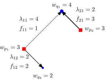
The Earth Mover’s Distance (EMD) is a metric that has shown promise as a means of measuring dissimilarity between point sets [56, 57]. Intuitively, it is the minimum amount of work needed to redistribute the point set representing one image (piles of “earth”) to cover the point set of another image (consisting of “holes”). A more formal discussion of the EMD is provided in Section 4.2.
The EMD is, however, a computationally expensive operation. In systems which employ it, economising on its use can lead to notable speed gains. At the same time, such schemes should not excessively degrade the system accuracy.
2.3
Overview
In this part of the dissertation, an approximation to exact query resolution using the EMD is proposed in the context of hand pose estimation.
CHAPTER 2. INTRODUCTION TO HAND POSE ESTIMATION 8
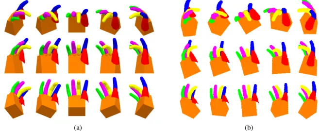
A coloured glove is used to emphasise the different fingers so that greater fidelity in pose reconstruction may be achieved. This also imposes a measure of uniformity on the input data, which allows the system to cater for a greater variety of users. Because the pose estimation system is to be used as a frontend for the tutor system, the use of a coloured glove is justified, as e-learning environments are more amenable to control than general settings. Note that the work detailed here was published in De Villiers et al. [24]. The presentation will follow this article, with extensions introduced after its publication being described in Chapters 7 and 8.
A two-tier search approach is demonstrated that uses an initial set of candidates obtained using a rough, but easily evaluated, metric. The set is then refined by applying the EMD. It is demonstrated quantitatively that approximate queries retain much of the accuracy of exact queries using the EMD directly. Furthermore, it is shown that the system outperforms a closely related hand pose estimation system, based on an evaluation using 500 real images of gloved hands with known ground truth.
In Chapter 3, an overview of hand pose estimation is provided. The properties of different pose estimation approaches are discussed. Finally, pose estimation systems closely related to the one presented in this dissertation are described and their characteristics explored. This provides the context to place the pose estimation system within the family of systems to which it belongs.
The theoretical foundations of similarity search in metric spaces are reviewed in Chapter 4, followed by a discussion of the EMD.
The hand pose estimation system itself is described in Chapter 5, while detailing each aspect of its operations with reference to similarities with and differences from existing systems.
In Chapter 6, the system is evaluated. It is demonstrated that approximate queries approach the accuracy of exact queries using the EMD while providing reductions in the time necessary to process a query. In addition, the system accuracy is compared with an existing system using real images obtained of a gloved hand.
An automatic colour calibration system is presented Chapter 7 which employs a graphical model to infer colour models given a calibration image.
Extensions to the pose estimation system necessary to track hand poses over video se-quences are related in Chapter 8.
Finally, conclusions drawn from the experimental evaluation of the system, and its exten-sions, are presented in Chapter 9.
Chapter 3
Survey of Hand Pose Estimation Methods
In this chapter, an overview of relevant hand pose estimation literature will be given. The first section will give a broad overview of the field. The second section will discuss techniques for estimating hand pose from single frames of video, with database driven pose estimation systems being such a technique. The remaining sections will consider in detail database driven systems which are closely related to the pose estimation system presented in this dissertation. In the final section, a critique of existing systems will be given which motivates the course of the research presented in subsequent chapters.3.1
Introduction
Hand pose estimation is a challenging subfield of human body pose estimation, due to a number of factors, the most important being the highly variable nature of the poses a human hand can assume. Detailed models of human hands may have more than twenty degrees of freedom (DOFs). For example, the system presented in this dissertation has four degrees of freedom per finger, three for hand orientation and three for hand position, giving 26 DOFs in total. Self-occlusion is common in hand poses, hiding appearance information needed for providing good estimates of these many degrees of freedom.
Hand pose estimation systems fall into three broad classes [29]. The first class is composed of those systems which attempt only a partial estimation of hand pose parameters. An example can be found in Von Hardenberg and B´erard [78], where the outstretched fingertips of a hand are searched for, and used to establish points of interaction between the user and a user interface projected onto a wall.
Partial pose estimation is not sufficient for sign language tutor software, simply because they must account for all possible variability in the user’s signing. So, the second and third group of hand pose estimation systems, systems which attempt a full reconstruction of hand pose, is more relevant to this work. These last two groups include model-based trackers, and single frame pose estimation systems.
Model-based trackers are top-down systems which use dynamic models of the human hand
CHAPTER 3. SURVEY OF HAND POSE ESTIMATION METHODS 10
to establish a frame-by-frame tracking of the hand. Model-based trackers, in general, explore a much smaller state space than single frame pose estimation systems, as they use the last frame of video as a point of departure when estimating the next frame’s pose. This can lessen the computational burden on such systems.
Model-based trackers have two chief weaknesses. The first is the need for initialisation. In general, such systems require the user to assume a known pose before the tracking algorithm can lock onto the hand, or they must perform single frame pose estimation at the start of the video sequence. The second weakness of such systems is the possibility of losing the track, meaning the system must be reinitialised. Model-based trackers do employ a variety of different strategies such as multiple hypothesis tracking to avoid losing track of the hand. However, especially in cases where the hands move rapidly, information about the previous hand pose is not necessarily as informative as in more limited settings, negating much of the advantage these trackers gain from taking into account neighbouring frames of video.
Single frame pose estimation systems have emerged recently as a means of solving general hand pose estimation problems [29]. These systems use only the information present in a single frame of video to generate pose candidates. This is inherently a more challenging problem than model-based tracking where a good initial pose estimate is available, and single frame pose estimation systems are in general more computationally complex than model-based alternatives. However, much is gained when a system can successfully estimate poses from a single frame of video. Such systems need no initialisation, although initial calibration of the camera and of any colour models (for example) might be necessary when the system is started for the first time. Without the need for initialisation, single frame pose estimation systems are ideal for (re)initialising model-based trackers, or for use on their own as hand trackers, possibly allowing multiple hypotheses to be tracked over time after single frame estimation has been performed.
The hand pose estimation system presented in this dissertation falls into this last category (single frame pose estimation systems). Because the system is to be used in a sign language tutor, the input is expected to contain rapid and unpredictable changes in hand pose. This is an ideal application for single frame estimation methods. In the next section, these methods will be discussed in more detail.
3.2
Single frame pose estimation systems
The category of single frame hand pose estimation systems, without further qualification, en-compasses many types of systems. However, the systems of interest to this discussion are those which are relatively flexible in the poses that they can recognise, and in some way consider the entire state-space either during learning or at runtime. A few systems that exemplify this class of approaches will now be given.
One means of estimating poses from single frames of video is to learn mappings between input features and hand pose parameters. For example, Rosales et al. [55] describe such a
CHAPTER 3. SURVEY OF HAND POSE ESTIMATION METHODS 11
system, where a set of mapping functionsφk are learnt which specialise in different regions of
the feature space. Each set of input features is mapped by the mapping functionsφk, producing a
candidate pose for each mapping function. The decision about which of the mappings to use as the final set of pose parameters is made using a feedback-matching function, which projects the mapping back into the feature-space. Each backprojection is then compared with the input using a distance measure (Rosales et al. employ the Mahalanobis distance based on the covariance matrix obtained using the training data). The candidate pose with backprojection closest to the input features is selected as the final pose.
It is also possible to use a branched cascade of classifiers to detect hand poses from a large set of possible poses. In such as scheme, a set of rectangular regions of various sizes is consid-ered which covers the entire image. Each of these regions undergo a series of tests. Each of the tests is performed by a classifier which either classifies the region as not containing an object of interest (and so the region is rejected), or it sends the region on for further tests. The Viola-Jones facial detector [72] operates in this manner, with a linear list of such rejection classifiers. A region is marked as containing a face candidate if all the tests succeed in sequence. Stenger et al. [66] use a tree of rejection classifiers to detect an unadorned hand with a fixed shape, but with variable orientation and position. At each non-leaf node of the tree, a region is either rejected, or it is sent to each child node for further testing. Each leaf represents a particular pose, and so if a leaf is reached, that pose has been detected. Stenger et al. demonstrate the system by quantitative testing of a variety of classifiers based on edge or silhouette features, and by showing a number of detection examples.
Another approach is to utilise inverse kinematics to infer the pose of the entire hand, given the location of the fingertips. Nolker and Ritter [50] proposed the GREFIT system, which uses two stages to extract pose parameters from hand images. The hands have a fixed orientation and a highly constrained position. The fingers of the hands are allowed to flex freely. An initial stage detects the positions of the fingertips within the image. Following fingertip detection, parametrised self-organising maps (PSOMs) [79] are used to map the fingertip locations to hand pose parameters. A PSOM is trained for each finger by using a hand model to generate fingertip positions given a set of joint angles (forward kinematics). At runtime, each PSOM then performs the inverse kinematic problem of finding finger joint angles given the fingertip position. The system is demonstrated by showing a number of successful pose detections from still images.
Finally, searching a large database of preprocessed pose candidates for items matching the input image has shown promise in solving hand pose estimation problems. As such a system is the topic of this part of the dissertation, a discussion of existing systems of this type will now be presented.
CHAPTER 3. SURVEY OF HAND POSE ESTIMATION METHODS 12
3.3
Database driven pose estimation systems
In this section, database driven pose estimation systems particularly relevant to this dissertation are first summarised briefly, and then discussed in more detail based on the characteristics which define such systems. The general functioning of this class of system was discussed in Section 2.1.
Athitsos et al. [6–10] demonstrated various systems which utilise a 3D model of an un-adorned hand, rendered from several viewpoints in order to obtain database elements. Edge images, extracted from both real and synthetic input, were used as features. The chamfer dis-tance [8] was used as the underlying dissimilarity measure between edge images. Because the chamfer distance is not a metric, a low-distortion embedding into a normed space is applied, allowing efficient spatial data structures to resolve queries in an approximate manner.
Dick, Zieren and Kraiss [27] introduced a conceptually similar system which was used to track a gloved hand for an interactive sign language tutor (detailed in Zieren’s PhD thesis [91]). Glove markers included coloured fingers, as well as a rectangular marker on the back of the palm. In order to speed recognition and keep the database compact, simple ellipse-shaped features for each finger were stored and used during comparison, with the Hausdorff distance between ellipses as the underlying metric.
The work of Grauman and Darrell [34] is an example of the Earth Mover’s Distance (EMD) being used in some form of pose estimation.1 Experiments were performed on a database of synthetically rendered silhouettes of human figures in various poses. They apply an embedding of the EMD into L1, due to Indyk and Thaper [38]. This allows the use of locality-sensitive hashing to speed (approximate) query resolution.
Wang and Popovi´c [80] demonstrated a system which uses a glove with a variety of patches in ten distinguishable colours. As features, they employ small resized versions of the segmented input image, called “tiny images”. The distance measure employed, the “tiny image distance”, shares certain features with the chamfer distance used by Athitsos et al. [8], as discussed in Section 3.7. To improve search performance, each database element is assigned a 192-bit binary code based on a learnt coding scheme which maps similar images to bit strings such that the Hamming distance between the bit strings is low. Approximate search using the Hamming distance may then be followed by a more detailed treatment using the tiny image distance. After initial pose estimation, inverse kinematics is used to refine the pose estimate.
Schr¨oder et al. [59] recently published an extension of the system described by Wang and Popovi´c which uses depth camera information. However, their explicit aim is extraction of hand location and orientation, rather than detailed hand shape estimation, and so is less relevant to the current discussion.
1Note that, while the hand pose estimation system presented by Ren et al. [53] does make use of the EMD,
it is fundamentally different from the system presented in this dissertation. Their system currently only processes frontal views of the inside of the hand, and is limited to making decisions about whether or not a finger is raised. Features are not true two-dimensional contour features, but are one-dimensional polar histograms derived from the segmented hand’s outer contour.
CHAPTER 3. SURVEY OF HAND POSE ESTIMATION METHODS 13
It is the specific functioning and assumptions underlying each of the system components in Figure 2.1 that uniquely characterises each database driven system. A more detailed dis-cussion of the aforementioned systems will now be presented, commenting specifically on the functioning of each of these specific subsystems.
3.4
Candidate parameter sets
Thepotentialaccuracy of database driven pose estimation systems is determined by the candi-date parameters sets. Each possible set of parameters corresponds to one entry in the database. The more elements in the database, the higher the potential accuracy of the system. How-ever, more entries imply the need for more memory, and for search procedures that can resolve queries with sufficient speed.
The systems in Athitsos et al. [6–10] vary in the number of database entries. The most recent case presented in [10] is intended for therecognitionof American Sign Language. The system is, therefore, geared towards hand shapes that commonly occur during the signing of this specific language. A total of 20 such hand shapes were chosen. Each of these shapes is considered from 4032 different viewpoints in the final database, implying a total of 80640 database entries.
Zieren [91] presented a hand pose estimation system intended for use in a sign language tutor. As such, the system attempts to reconstruct arbitrary hand shapes. To do this, each finger was allowed to assume a discrete set of possible poses, with the thumb, index finger, middle finger, ring finger and pinky fingers having 7, 9, 8, 9 and 9 settings respectively. Therefore, a total of 7×9×8×9×9=40824 hand shapes can be recognised by the system. This number was reduced to 23352 by eliminating physiologically improbable combinations of finger poses. Each hand shape was considered from 105 possible viewpoints. Thus, the database included 23352×105=2451960 postures.
The database elements need not necessarily be defined explicitly. The database of candi-dates in Grauman and Darrell [34] contained a set of 136500 randomly generated body pose parameter sets.
Wang and Popovi´c [80] use a set of 18000 hand pose parameters captured using a data glove which include poses from fingerspelling2, “common” hand gestures and random finger motions. They use the root mean square (RMS) distance between corresponding vertices of the synthetic model to sample a smaller subset of these pose parameters such that the elements of the subset are maximally separated. This subset of pose parameters is used to generate synthetic hand images, each rendered from multiple viewpoints, with a final database of 100000 elements.
CHAPTER 3. SURVEY OF HAND POSE ESTIMATION METHODS 14
(a) (b) (c) (d)
Figure 3.1: Features on which the existing systems operate: (a) the bounding ellipse features similar to those used in [91] with the image edited to resemble the glove used in that publication. (b) Canny edge-detector features used by Athitsos et al. [6–10]. This system used anunadornedand not a gloved hand. (c) Silhouette features of the type employed by Grauman and Darrell [34]. This system extracted silhouettes from whole body poses. (d) “Tiny image” features used by Wang and Popovi´c [80]. The seg-mented input image is resized to a 40×40 raster, which forms the final features. This system employed a different glove design to that shown here.
3.5
Synthetic model
The 3D model used for rendering the pose parameters has a strong influence on the types of input images that may be processed.
Both Athitsos et al. [10] and Grauman and Darrell [34] made use of the commercially available Poser 5 [23] to render, respectively, an unadorned human hand and a full human body in various poses. As such, their systems are more generally applicable, but this has negative implications for the information available to the pose estimation system.
If a system makes special requirements of the user, such as requiring a coloured glove, then the synthetic model must reflect this. Zieren [91] made use of an OpenGL model of a gloved hand adorned in the same manner as required of the user. Each finger is coloured uniquely, and a marker is also placed on the back of the hand. While such systems are not generally applicable, they are useful when controlled environments can be reasonably expected. The additional information and better uniformity of the input data has positive implications for the accuracy of these pose estimation systems.
In the case of Wang and Popovi´c [80], the glove design is produced algorithmically by choosing 20 seed triangles that are maximally separated in the synthetic glove model mesh. The seed triangles are randomly assigned one of a set of ten colours, and the rest of the model mesh triangles are coloured based on their nearest neighbouring seed triangle. The glove is then manufactured based on the results of this process.
CHAPTER 3. SURVEY OF HAND POSE ESTIMATION METHODS 15
3.6
Feature extraction
The feature extraction phase determines the type of information the system uses. All the systems discussed here make use of some form of contour features, though they are represented in different ways. The features used by each system are illustrated in Figure 3.1.
Zieren [91] approximated the different coloured markers on a user’s glove using bounding ellipses. This served as a set of approximate contour features (each contour is associated with either a finger, or the back of the hand, based on the colour of the inside of the contour).
The system in Athitsos et al. [10] extracts edge images using the Canny edge detector [21]. The edge images themselves form the features on which the system operates.
Grauman and Darrell [34] extracted the silhouettes of the images of interest, and represented them as approximating point sets.
Wang and Popovi´c [80] used the segmentation of the input image into marker regions di-rectly by resizing the segmented image to a resolution of 40×40. The resulting images are referred to as “tiny image” features.
3.7
Database index generation and lookup
The key components of database driven pose estimation systems are the database index genera-tion and lookup subsystems. Database index generagenera-tion determines how the data in the database is structured, so that runtime queries can be processed with sufficient speed. Ultimately, the de-sign of this subcomponent depends on the set of features extracted from input images, and the dissimilarity measure defined between them.
Because the rendering of a synthetic pose candidate is too processor intensive to occur at runtime, the features must be precalculated. The average size of the set of features associated with a synthetic image, along with the number of entries, determines thesizeof the database.
The structure of the database is dependent on the properties of the dissimilarity measure used to compare candidates. Large portions of the database can be eliminated quickly during lookup if a dissimilarity measure with convenient mathematical properties is chosen.
Since the bounding ellipses are especially simple features, Zieren [91] stores these features directly as was illustrated in Figure 3.1a. The Hausdorff distance [89] is then used as a distance measure to compare the input with database elements. Key concepts underlying this metric are illustrated in Figure 3.2. The Hausdorff distance is defined between two sets of points, in this case the sets of points defined by two ellipses. It can be interpreted as the maximum distance an adversary can force one to walk to get from either point set to the other. IfA andBare the sets of points belonging to the two respective ellipses, then the Hausdorff distance between the setsAandBis H(A,B) =max(max a1∈A min b1∈B d(a1,b1),max b2∈B min a2∈A d(a2,b2)).
CHAPTER 3. SURVEY OF HAND POSE ESTIMATION METHODS 16 Ellipse A a1 b1 b2 a2
d1= maxa1minb1d(a1, b1)
d2= maxb2mina2d(a2, b2)
Ellipse B
H(A, B) = max(d1, d2)
Figure 3.2:Illustration of the Hausdorff distanceH(A,B)between the ellipsesAandB.
Note that the setsA andB can be chosen arbitrarily, provided that the distance measured
operates on all their elements. In this case, they are the points on an ellipse, but more general contours or point clouds are also a possibility.
In Zieren [91], d is chosen as the Euclidean distance between two points (making H a metric by virtue ofd being a metric [89]). The database entries are stored in a tree structure, with similar elements stored near each other in the tree. The distance measure employed during the search procedure is the sum of the squares of the Hausdorff distance between the individual ellipses representing each finger’s marker and the marker on the back of the hand.
When the dissimilarity measure is more computationally complex, using it directly is not feasible. Typically, some means of approximating the measure must be provided. This is often done by embedding the features into a lower dimensional space, where an approximate measure may be used to compare candidates.
The systems in Athitsos et al. [6–10] use (in various stages of development) the symmetric chamfer distance as the core dissimilarity measure. In its asymmetric form [8], the chamfer distance is given by
dAC(X,Y) = 1
|X|x
∑
∈Xminy∈Y ||x−y||.Here,X andY are the two sets of edge contour points obtained from edge detection on the two hand images being compared. |X|is the number of edge contour points inX, and||x−y||
is the Euclidean distance between a pair of points fromX andY. Essentially, the asymmetric chamfer distance is the normalised sum of the minimum distances from each point inX to some point inY. Figure 3.3 illustrates the type of features expected by this metric, and the matches between the point setsXandY involved in calculatingdAC. For the examples given in the figure, the asymmetric chamfer distances are given by
CHAPTER 3. SURVEY OF HAND POSE ESTIMATION METHODS 17 y1 y2 x1 x2 x3 (a) y1 y2 x1 x2 x3 (b)
Figure 3.3: The matches involved in calculating the asymmetric chamfer distance are illustrated in (a) and (b) fordAC(X,Y)anddAC(Y,X)respectively, whereXis the set of red filled pixels, andY is the set of blue hatched pixels. These sets of pixels represent the edge features from different images, as illustrated, for example, in Figure 3.1b. After finding the closest matches in the target set for each point in the source set, all the distances represented by the arrows are added, and then divided by the number of points in the source set.
dAC(X,Y) = 1
3[d(x1,y2) +d(x2,y1) +d(x3,y1)] and
dAC(Y,X) = 1
2[d(y1,x3) +d(y2,x1)].
For use in their work, Athitsos et al. define a symmetric form of the chamfer distance as
dSC(X,Y) =dAC(X,Y) +dAC(Y,X).
In Section 4.2.3, the relationship between the chamfer distance and the EMD will be dis-cussed. It will also be noted that the chamfer distance is susceptible to noise pixels, as a single noise pixel can match to any nearby pixels in the synthetic point set. The EMD resists this by keeping account of all matches, and ensures that small regions only have minor influence on the final result.
Because the chamfer distance is not a true metric, Athitsos et al. use Lipschitz embeddings to embed each database element into a normed space. This involves choosing N reference imagesInfrom the database. The Lipschitz embedding of the edge imageX is then the vector
L(X) = [dSC(X,I1),dSC(X,I2), . . . ,dSC(X,IN)].
The underlying intuition is that two imagesX1 andX2 which are similar will have similar distances dSC(X,In) from the reference images, and so will have similar embeddings. This representation has the advantage that the embedding is a vector, and so all search methods applicable to vector spaces are relevant. In addition, the embeddings of all the synthetic images
CHAPTER 3. SURVEY OF HAND POSE ESTIMATION METHODS 18
5
3 1 1 0
0 1 1 0 1 1 0 0 0 1 0 0 0 0 0 0
5
3
1
1
0
1
1
1
1
1
0
0
0 0 0 0
0
0
0 0
0
2
1 1 1 1
1
2
1
2
1
2
1
2
1
2
1
2
1
2
1
2
1
2
1
2
1
2
2
1
1
2
1
2
1
2
1
2
×
Grid 12 Grid 1 Grid 210
3 1 1 0
1
2
1
2
1
2
1
2
1
2
=
0
0
0 0 0
0 0 0 0 0 0
[
[
[
]
]
]
Point counts Side lengths EmbeddingFigure 3.4:An illustration of theL1embedding of the EMD due to Indyk and Thaper [38]. Given a set of points with discretised locations, a vector is formed by concatenating the cells of progressively finer grids. Each cell contains the number of points within that cell, and each grid is finer than its predecessor by a factor of 2. Each cell is scaled by its side length, where the finest level has a side length of 12. This embedding is employed by Grauman and Darrell [34] to embed silhoutte point features, similar to Figure 3.1c, intoL1.
can be precalculated, and the chamfer distance only needs to be calculated between the image and theN reference images to obtain the input image embedding.
Athitsos et al. select the reference imagesIn by using a method of their own development called BoostMap which adapts ideas from AdaBoost [32] to the context of embeddings.
In Grauman and Darrell [34], the features are point sets extracted from the silhouettes of body poses (either real or synthetic). They apply an embedding of the EMD intoL1, due to Indyk and Thaper [38], who also provide theoretical guarantees on the degree of distortion induced by the embedding. The embedding is illustrated in Figure 3.4. Because the distance metric is now theL1(Manhattan) distanced(v,w) =∑n|vn−wn|locality-sensitive hashing [62]
can be used to speed approximate query resolution.
The distance measure used by Wang and Popovi´c [80] is similar to the symmetric chamfer distance, except the squares of the distances between points are added, provision is made for multiple region types, and the square root of the final result is taken. The measure penalises at each pixel of the image according to how distant the nearest pixel of the same type is in the other image. An asymmetric version of the “tiny image distance” (denoted bydAT here) is defined first dAT(ri,rj) = s 1 |Ci|(x,
∑
y)∈C i min (u,v)∈Sxy [(u−x)2+ (v−y)2]CHAPTER 3. SURVEY OF HAND POSE ESTIMATION METHODS 19
whereri andrj are tiny image features. Ci is the set of non-background pixels in the tiny
imageri. Sxy is the set of tiny image pixels in rj which have the same value as the pixel at
(x,y) in the imageri. The tiny image distance is then defined as a symmetric version ofdAT, exactly as it is done in [8]
dST(ri,rj) =dAT(ri,rj) +dAT(rj,ri).
As this dissimilarity measure is non-trivial to calculate, binary codes are generated for each tiny image based on a method proposed by Torralba et al. [68] which maps similar tiny images to binary codes which are close in terms of their Hamming distance. The hand pose estimation system employs a search using the Hamming distance, followed by a refinement step using the tiny image distancedST.
3.8
Conclusion
This chapter has presented an overview hand pose estimation, and in particular a set of closely related database driven pose estimation systems. Types of systems discussed include model-based trackers and a variety of single frame pose estimation systems.
Model-based hand trackers exploit time coherence between successive frames of video to track changes in hand pose. However, the speed and unpredictability of hand motions during signing undermines these time coherence assumptions, rendering model-based trackers less suitable for application in sign language tutors. Single frame pose estimation systems do not rely on time coherence assumptions, and so can more readily deal with such rapid changes. Techniques for performing single frame pose estimation include inverse kinematics, learning mappings of features to pose parameters, forming classification cascades and database-driven search for pose candidates.
Inverse kinematic techniques rely on being able to identify relatively high-level information about the hand, such as the location of the fingertips, which are challenging to identify when compared with low-level features such as edges or coloured regions. In addition, a good es-timate of the hand pose must be available, such as in Wang and Popovi´c [80], or it must be fixed as in [50]. The reliance on higher-level features and pose information are obstacles to employing inverse kinematic techniquesin isolationfor a tutor system.
While promising, learning mappings of input features to parameters and classifier cascades created using boosting techniques may suffer from scarcity of real training data. If the hand pose is allowed to vary freely, providing sufficient amounts of real images with ground truth data to adequately cover the state space is challenging. However, learning synthetic data introduces the risk of overfitting on spurious regularities in the synthetic data. At the same time, gathering of sufficient test data is hampered by the same state space size considerations as in the collection of training data.
CHAPTER 3. SURVEY OF HAND POSE ESTIMATION METHODS 20
Instead, using a fixed but perceptually meaningful metric has no risk of overfitting.3 This is the approach employed by database-driven methods. While concerns about the accuracy of the model used to generate the database remain, there is no opportunity for spurious regularities in the synthetic model to become deciding factors in the estimation process.
Several existing database-driven systems were discussed. Athitsos et al. [8] and Grauman and Darrell [34] employ markerless tracking, but this unnecessarily lowers the amount of infor-mation available to the tracker when, for sign language tutors, it is reasonable to expect a user to wear coloured gloves.
Coloured gloves enable simple, yet powerful, similarity searches. In particular, being able to separate the finger markers immediately leads to perceptually meaningful and rapidly evalu-ated, metrics which compare the approximate appearance of corresponding fingers. Zieren [91] provides an example of such a simple marker-based metric. However, used in isolation, such metrics are not able to consider detailed hand shape.
The glove-based approach employed by Wang and Popovi´c [80] is promising, though ques-tions for further investigation arise. Spatially separated regions of the glove have similar colour-ing. While it is possible that the exact configuration of all coloured regions may be a sufficiently strong indicator of the true hand pose, the possibility that identically coloured regions act as mu-tual confusers needs to be addressed. In addition, the distance measure uses searches for nearest pixels which may be sensitive to segmentation noise.
The hand pose estimation system presented in this dissertation makes use of coloured gloves to take advantage of the greater environmental control afforded to tutor systems. A glove similar to that of Zieren [91] is adopted. However, a more detailed form of similarity metric, the EMD, will be employed. While being more informative than the Hausdorff-distance metric employed by Zieren [91], the EMD is also less sensitive to noise pixels, as opposed to chamfer distance type dissimilarity measures such as employed by Athitsos et al. [8] and Wang and Popovi´c [80]. In the next chapter, the theoretical underpinnings of similarity search in metric spaces will be presented in more detail and the EMD will be defined formally. These techniques will subsequently be employed to develop the tutor’s hand pose estimation system.
3The choice of a “perceptually meaningful” metric could be construed to be the avoidance of overfitting in
the sense of consciously avoiding brittle metrics. For example, the use of the Euclidean distance on the vector of image pixels is usually a poor choice in that it does not take into account similarity considerations appropriate to images.
Chapter 4
Similarity Search in Metric Spaces
Metric spaces [89] are a powerful tool for performing similarity search within databases that contain vast numbers of candidates. These spaces preserve the familiar concept of distance from geometry while generalising it to include a much greater variety of objects as possible points in space.
In this chapter, the properties of metric spaces and how these relate to similarity search are discussed. Theoretical matters which are common to all application domains are considered first, with the focus gradually shifting to human body/hand pose estimation, in particular using the Earth Mover’s Distance (EMD). The functioning of exact search methods will be outlined, after which methods for accelerating and approximating these exact techniques will be consid-ered.
Formally, a metric space is an ordered pair(S,d), whereSis a set of objects of interest (anal-ogous to points in space), anddis a distance measure defined between objects inS. The distance measuredmust exhibit the following properties (wherex,yandzare elements ofS) [89]:
d(x,y)≥0 . . .non-negativity
d(x,y) =d(y,x) . . .symmetry
d(x,y) =0 ⇐⇒ x=y . . .identity
d(x,z)≤d(x,y) +d(y,z) . . .triangle inequality.
Together, these properties preserve key notions central to intuitions regarding distance. A distance measure that satisfies all of these requirements is called a metric.
The first property ensures that distances are always positive, while the second property requires that the distance from one point to another is the same as that of the return journey. The third property states that the distance between two points is zero if and only if they are the same point. The fourth property guarantees that the distance of a route between two points that goes via a third point is always at least as large as the direct route between the two endpoints.
CHAPTER 4. SIMILARITY SEARCH IN METRIC SPACES 22
The Euclidean distance in Rn is an obvious example of a distance measure that exhibits these properties. It is important to note, however, that there is nothing in these properties that constrains the nature of the objects inSto be vectors. They may be documents or sets of points or images, or any other domain of interest. This is one source of the flexibility of metric spaces as a tool for similarity search.
4.1
Similarity search in databases
Nearest neighbour search is a simple yet powerful technique for finding candidates most similar to a given item amongst a large number of potential matches stored in a databaseD⊂S.
Given some measure of dissimilarity d, one can, in principle, determine the distance be-tween the query object x and all possible candidates x0 ∈ D, retaining those candidates for whichd(x,x0)is smallest.
However, if there are no restrictions placed ond, this strategy quickly becomes impractical as the number of potential candidates grows. This is particularly evident when the distance measured is computationally expensive. As there is no way of knowing even approximately whatdwill be until it is calculated in each case, all items need to be considered.
Requiring thatdbe a metric enables search strategies which are able to discard large portions of a database based on distances calculated between the query object and selected items in the database called pivot objects. The selection of pivots and the manner in which these distance calculations are used to eliminate candidates is specific to the algorithm employed.
4.1.1
Vantage point trees
As an example of such a search strategy, the vantage point tree (or VP-tree) [85] will be con-sidered. Essentially, VP-trees are a kind of binary space partitioning scheme, but generalised to metric spaces.
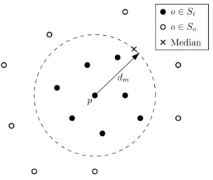
A key concept employed in this scheme is that of a ball partition. Given some pivot object
p, the set of database elementsD can be divided into setsSi andSo by specifying a radiusdm
such thatSi are all the elements closer than dm to the pivot and So all those elements further thandmfrom the pivot.
Si={o∈D·d(o,p)≤dm} So={o∈D·d(o,p)≥dm}.
Choosing the radiusdmto be the median of the distancesd(o,p)ensures that the two sets are equal in size (objects on the dividing radius are shared between the partitions for this reason).
This type of partitioning is referred to as a ball partition, because it is analogous to dividing points inR3into two regions using a spherical surface centred at pwith radiusdm. This idea is illustrated in Figure 4.1.
CHAPTER 4. SIMILARITY SEARCH IN METRIC SPACES 23 p dm o∈Si o∈So Median
Figure 4.1:Conceptual view of a ball partitioning. Note that the median element is shared between the two partitions.
A vantage point tree consists of a binary tree where each node contains a pivot (also known as vantage points), usually selected by means of some heuristic. At the root, a ball partition is made based on the root pivot, and the two partitions are each assigned as a subtree. This process continues recursively until each leaf has less than a predetermined number of elements.
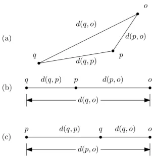
Given a query object q, one can find nearest-neighbours for q by recursively descending through the binary tree. At each node, the distance from the query object to the pivot is calcu-lated. Using the distance from the query object to the pivotd(q,p)and the distance from the pivot to the median objectdm, various constraints can be imposed on the distance between the query object and any objectoin eitherSiorSo. For example, from the triangle equality it can be shown that [89]
|d(q,p)−d(p,o)| ≤d(q,o)≤d(q,p) +d(p,o).
This is known as the object-pivot distance constraint. The constraint is illustrated in Figure 4.2. The right-hand restriction is derived from the case whered(q,p)andd(p,o)reinforce each other such that the path fromq too via p is the same length as the path directly from qto o. The left-hand constraint emerges in the case whered(q,p)andd(p,o)work against each other. Other constraints also naturally emerge from the properties of the metricd, some involving both parent and child pivots. These constraints can be used to eliminate large portions of the database using a minimal number of distance calculations.
Having discussed the general principles underlying similarity search in metric spaces, the key metric of interest to this dissertation, the EMD, will now be presented.
![Figure 3.1: Features on which the existing systems operate: (a) the bounding ellipse features similar to those used in [91] with the image edited to resemble the glove used in that publication](https://thumb-us.123doks.com/thumbv2/123dok_us/1583343.2712892/28.893.126.769.116.319/figure-features-existing-systems-bounding-features-resemble-publication.webp)