MANAGING AGENT PLATFORMS WITH THE
SIMPLE NETWORK MANAGEMENT
PROTOCOL
by
Brian Douglas Remick
A thesis submitted to the faculty of The University of Utah
in partial fulfillment of the requirements for the degree of
Master of Science in
Computer Science
School of Computing The University of Utah
Copyright Brian Douglas Remick 2002 All Rights Reserved
T H E U N I V E R S I T Y O F U T A H G R A D U A T E S C H O O L
SUPERVISORY COMMITTEE APPROVAL
of a thesis submitted by
Brian Douglas Remick
This thesis has been read by each member of the following supervisory committee and by majority vote has been found to be satisfactory.
__________________ ______________________________________ Chair: Robert R. Kessler
__________________ ______________________________________ Matthew Flatt
__________________ ______________________________________ Dick Cowan
To the Graduate Council of the University of Utah:
I have read the thesis of Brian Douglas Remick in its final form and have found that (1) its format, citations, and bibliographic style are consistent and acceptable; (2) its illustrative materials including figures, tables, and charts are in place; and (3) the final manuscript is satisfactory to the supervisory committee and is ready for submission to The Graduate School.
_________________________ ______________________________________
Date Robert R. Kessler
Chair: Supervisory Committee
Approved for the Major Department
_________________________________________________ Thomas C. Henderson
Chair/Dean
Approved for the Graduate Council
_________________________________________________ David S. Chapman
ABSTRACT
Management of agent platforms is an inherently difficult problem given the flexibility and ambiguity associated with autonomous mobile agents. Their distributed nature, however, draws an analogy to distributed networks, an area in which
management has been well researched. This research applies a network management solution using the Simple Network Management Protocol (SNMP) to managing agent platforms.
Utilizing the flexibility of SNMP, a formal interface is defined for management of a FIPA-compliant agent platform. A specific proxy agent implementation of this interface for the JADE agent platform implementation is also developed. The resulting
management system, AgentSNMP, is integrated with an off-the-shelf enterprise management system, HP Openview, as a proof of concept. The result is an efficient, flexible means of managing agent platforms.
TABLE OF CONTENTS
ABSTRACT... iv LIST OF TABLES ... ix LIST OF FIGURES ...x ACKNOWLEDGEMENTS... xii 1. INTRODUCTION ...1 2. MOTIVATION ...22.1 Complexity of Agent Platforms ...2
2.2 Lack of Formal Management Specification...3
3. MANAGEMENT REQUIREMENTS ...4
3.1 Standard Management Tasks...4
3.2 Load Balancing...5
3.3 Agent Mobility ...7
3.4 Agent Communication ...8
3.5 Unresolved Requirements...9
4. NETWORK MANAGEMENT BACKGROUND...10
4.1 Proxy Agents...10
4.2 Protocols ...12
4.3 Management Techniques...12
4.4 Management Software...15
5. COMPARING AGENT PLATFORMS TO NETWORKS...17
6. SNMP BACKGROUND ...19
6.1 Management Information Bases (MIBs)...19
6.2 Protocol Specifics ...23
6.3 MIB Data Structures...24
6.4 Notifications ...26
vii
8.2 AgentX Master Agent Layer ...33
8.3 Management Layer ...33
9. FIPA MIB DESIGN ...34
9.1 Design Considerations...34 9.2 MIB Specification ...35 9.3 Levels of Analysis ...36 9.4 Channels ...38 9.5 Use of Notifications ...42 9.6 Creation Groups...42
9.7 FIPA Specification Adherence ...43
10. PROXY AGENT DESIGN...44
10.1 Implementation Overview ...44
10.2 Interaction with JAX Framework...47
10.3 Object Interactions ...48
10.4 Thread Communication and Control ...50
10.5 Load Analysis...53
11. ENTERPRISE MANAGEMENT INTEGRATION ...56
11.1 MIB Browser Integration...57
11.2 HP Openview...57
11.3 Agent Management Plugin ...62
12. MANAGING PATTERNS OF AGENT INTERACTION...71
12.1 Agent Pattern Development...71
12.2 Management Scenarios...75
13. PERFORMANCE COST CONSIDERATIONS...86
14. ASSUMPTIONS AND LIMITATIONS...89
14.1 FIPA Platform Specification ...89
14.2 Access to Managed Data ...89
15. FUTURE WORK ...91
15.1 FIPA Specification for Management...91
15.2 Higher-Level Constructs ...91
viii
16. RELATED RESEARCH...93
16.1 Moving Toward Decentralized Management...93
16.2 Using Mobile Agents as Proxy Agents...94
17. CRITICAL EVALUATION...95
17.1 JADE Platform Events ...95
17.2 AgentX Framework...96
17.3 HP Openview...97
18. CONCLUSION ...99
APPENDIX: FIPA MIB DETAILED SPECIFICATION...100
LIST OF TABLES
Figure Page
1. MIB object definition properties...21
2. FIPA MIB high-level description...37
3. Message table entries for message routing scenario. ...40
4. Channel table entries for message routing scenario...40
5. Description of class functionality in AgentSNMP...46
6. Compiler-generated MIB base classes and corresponding derived classes. ...49
7. Translations from MIB notifications to plugin GUI responses...66
8. Translations from GUI actions to plugin MIB responses...67
9. PlatformLoadAgent options. ...72
10. ServerAgent options...73
11. Platform group MIB objects. ...101
12. Host group MIB objects...102
13. Agent table MIB objects...103
14. Behavior table MIB objects...104
15. Channel table MIB objects...105
16. Message table MIB objects...105
17. Agent creation MIB definitions...106
LIST OF FIGURES
Figure Page
1. Standard centralized network management scheme...14
2. Standard MIB tree structure...20
3. MIB usage in SNMP ...22
4. Table structure in SNMP...25
5. Nesting of tables in a MIB structure...26
6. A flat table representation in a MIB structure ...27
7. Architecture of the agent management system...31
8. Conceptual view of a channel between two agents. ...39
9. Graphical representation of channels between agents ...41
10. Class diagram of the JADE proxy agent framework...46
11. Example of an SNMP request originating from a manager...49
12. Object interaction when platform events occur...51
13. Object interaction when platform events occur...51
14. Thread control/communication between threads in JADE proxy agent ...53
15. Communication between remote and local SNMP agents in ping operation...55
16. Screen capture from the MG-SOFT MIB browser application ...58
17. Screen capture from HP Openview MIB browser...59
xi
22. Graphical interface to PlatformLoadAgent ...72
23. Graphical interface to client/server and mobility pattern ...74
24. Screen capture of platform load pattern in Openview ...77
25. Graph of PlatformLoadAgent response time ...79
26. Screen capture showing client/server pattern in Openview ...80
27. Graph of ServerAgent response time as client count increases...81
28. Screen capture of client/server pattern in Openview with two servers ...82
29. ServerAgent response time with 50 client agents...83
30. ServerAgent response time with 50 client agents and additional server ...83
31. Screen capture of agent migration pattern on remote machine ...85
ACKNOWLEDGEMENTS
Special thanks go to my advisor, Robert Kessler, as well as the members of my committee, Matthew Flatt and Dick Cowan. Thanks also to Klaus Wurster at Hewlett-Packard for providing the Openview software used in this research and assisting in development with Openview.
1. INTRODUCTION
Agent systems are quickly becoming a popular means of implementing complex distributed systems. Their ability to communicate independently without a central control mechanism and their ease of implementation make them an attractive software solution to many scenarios.
The need to manage these systems is already becoming increasingly important. Details of agent communication and overload conditions are difficult to find in such a distributed environment, and general software debugging tools fail to provide adequate context of the system as a whole. Agent-based systems have an inherent tradeoff in that, while being extremely flexible, the entire system is often difficult to manage.
This research shows that network management techniques, coupled with SNMP (Simple Network Management Protocol) [1], provide a solution to this problem. The flexibility of the protocol as well as the availability of powerful, off-the-shelf enterprise management packages that already support SNMP makes it an ideal fit for managing agent-based systems.
2. MOTIVATION
The motivation behind this research stems from the following areas:
• Complexity of agent platforms
• Lack of a formal management specification
2.1 Complexity of Agent Platforms
Although software systems that utilize agent-based technology benefit from its flexibility, they quickly become extremely complex. The need to manage these systems both during development and use is a requirement.
The idea of formally managing an agent system is relatively new. Since agent-based systems are used most often in research (so far), management needs arise from the software developers themselves, who are interested in watching the interactions between agents as well as the system load. Developers often find that a traditional debugger does not have the context necessary to show them the information they need. The result is typically a custom management implementation that is tied closely to their specific agent system as well as the specific information they need to manage. While this might solve the individual developer’s needs, other developers will undoubtedly
encounter the same scenario in other systems, but they will not be able to easily reuse the same management software.
management are implementation-specific and thus are not addressed in the high-level architecture of the system [2], [3].
The Agent Management System (AMS), a central component of each agent platform, provides supervisory control over the system, providing methods for registering new agents, naming agents, etc. However, the AMS does not expose any management functionality to external clients. (For instance, there is no standardized means of querying a platform for its current state.) This has led to the development of platform-specific mechanisms to access this type of information. The JADE agent platform implementation [4], for example, has developed an Introspector agent that provides feedback on platform events and agent communication. However, this type of functionality is only available via platform-specific additions to the AMS standard, which cannot be easily generalized to a standard management scheme.
While the FIPA architecture is correct in assuming that managing an agent platform is dependent on implementation details, the lack of a standard has led to inconsistent management techniques. This research formalizes the concept of managing an agent platform and provides a standard solution that will work for all FIPA implementations.
3. MANAGEMENT REQUIREMENTS
In order to be effective, the system must meet the basic requirements of managing an agent platform and be flexible enough to allow more specific management scenarios to be easily adapted. The following requirements are essential to managing an agent platform, regardless of its implementation.1
3.1 Standard Management Tasks
A manager should be able to perform some basic operations on agents within a platform:
• Obtain the configuration of a platform, including information about the number of host machines that exist on the platform and a list of agents living on each machine.
• Create new agents.
• Destroy agents.
• Change the state of an agent, such as pause execution.
• Add/remove host machines from a platform.
• Move agents between hosts.
operations are implementation dependent, and most platforms do not provide a complete set of these operations to an outside software client.
3.2 Load Balancing
A management system needs to be able to identify agents within a platform that are degrading the performance of the platform and make changes to achieve balance within the system. This abstract idea is defined as load balancing in this research.
3.2.1 Defining Agent Load
Agents that fit the characteristic above are overloaded, meaning they are stressing some inherent limitations of the agent platform. Potential limitations can be partitioned into the following categories:
3.2.1.1 Physical Resources
Normally, the abstract design of an agent platform will be logically mapped to either one computer or a set of computers. It is likely that at some point during the agent platform’s lifetime, agents within a particular host machine will begin to push the machine’s physical resources in terms of memory usage, CPU usage, or network bandwidth.
Consider, for example, an e-service provider that has an agent platform running on a web server. As new customers arrive to query the service for information (in the form of agents), e-service agents are dispatched to communicate with customers and answer questions as well as to collect sales information. For ease of organization, the company has set up host machines to logically map to geographic regions. For example, upon arrival, each customer agent is moved to the machine that represents the geographic area where the customer lives.
At any given time, a large number of customers from a particular region may use the e-service, causing a sudden increase in the number of agents running on the same machine. Together, these agents will undoubtedly exhaust the machine’s physical resources.
3.2.1.2 Programmatic Resources
Despite their ease of implementation, distributed agents are difficult to debug in a distributed environment. Agents that are developed and tested in a small, controlled agent platform may function incorrectly when placed in a much larger, complex agent community. They may begin to exhibit much higher response times compared to the controlled environment due to internal data structures getting much larger. In this sense, agents can exhaust the programmatic resources allotted to them at the time of
development.
As an example, consider a case where a relatively slow dictionary data structure was chosen during development of an agent to maintain state during the agent’s lifetime. The agent functioned perfectly during testing on a small agent platform, since
small, the agent is programmatically stressing the system due to decisions made in the development process.
A management system needs to be able to identify either of the situations above on a per-agent basis and react to them in a way that balances out the system. This might involve redistributing agents to other machines and/or creating new agents to accommodate some of the load.
This research will assume the following characteristics are sufficient to identify overloaded agents within a platform:
1. Communication level of the agent (type/number/size of messages sent/received)
2. Resources being used on the host machine (CPU time, memory usage, etc.) 3. Agent response time (how long agents take to respond to requests, if applicable)
Knowledge by the management system is then necessary to combine these factors and determine if a particular agent is overloaded and what action should be taken. This research provides access to the necessary data so that a manager can make this decision effectively.
3.3 Agent Mobility
Agents have the ability to move between machines and even between entire platforms. Managers must be knowledgeable about the location of agents at all times
and must be informed when they change locations. New agents that arrive from other locations should be recognized by the management system and added to the set of managed agents.
In the e-service example above, customer agents that are moved to their corresponding regional e-service machine should be immediately within the
management system’s domain, allowing the manager to keep track of customer agents’ resource usage on the system and their interactions with e-service agents.
3.4 Agent Communication
An effective agent management system must have the ability to analyze
communication between agents on a platform. This might mean watching individual messages passed between agents on a platform or merely analyzing the number of messages that have been processed by a particular agent.
Consider again the e-service example described above. A manager of this system might want to know characteristics of conversations that take place between e-service agents and arriving customers. For instance, the manager might want to know how many messages are required on average to finish a transaction with a customer or how many customers leave without making use of the service (due to high prices,
unavailable merchandise, etc.)
Note that analyzing agent communication in this context is a more involved form of agent communication analysis than what was necessary for load balancing discussed above. The intent here is to capture not only the level of communication and the response time of agents but also the patterns underlying the communication.
3.5.1 Security
Should a manager have complete access to every agent on a platform (i.e., the ability to change agent state, destroy agents, etc.)? In an e-service scenario, customers would probably not want a manager of the e-service to be able to inspect all aspects of their agent, especially if their agent contains sensitive information like an address, phone number, or credit card numbers.
3.5.2 Advanced Mobility (Agent Scope)
When an agent leaves a platform, is it out of the management domain? Does the manager need to have some record that the agent left the system? Does the manager need to “follow” the agent to its new location?
4. NETWORK MANAGEMENT BACKGROUND
Network management is a key analogy used during this research. Since the fundamentals of network management are very similar to agent management, it is important to understand some background of managing networks and the types of systems available.
Network management has been a topic of research for many years. Researchers in both academic projects and in industry are continually trying to find the most flexible, scalable, and easy-to-use network management system to match growing industry requirements.
The following sections describe some aspects of network management that provide background for this research. They describe the basic components of a typical network management system, all of which will have corresponding roles in this research.
4.1 Proxy Agents
Proxy agents2 are commonly used in network management as monitors for
resources. These “agents” are typically pieces of software distributed around the network to act as representatives for the resources that need to be managed. (Managed
2 Network management uses the term “agent” to describe a software process that monitors a
particular resource and provides information to a network manager. To avoid confusion with agent-based systems that are the focus of this research, the term “proxy agent” will be used where possible to describe these agents.
expose a standard interface to it. This interface is used by management systems to query and change attributes of the device. Proxy agents are generally also capable of
broadcasting events, called notifications or traps, to any listening management systems. For instance, a printer is a commonly managed network resource. A typical interface for a printer that a proxy agent might expose would look something like the following (written as a pseudo C-style API):
[methods]
int getPaperCount(); // returns paper remaining in printer
int getTonerLevel(); // returns the amount of toner left
int getJobQueueSize(); // returns the number of jobs waiting
void purgeJob(int job); // purges a job from the queue
void reset(); // resets the printer to its default state
[traps]
OutOfPaperError // thrown when the printer is out of paper
OutOfTonerError // thrown when the printer is out of toner
Using this interface, a management system could manipulate attributes for almost any type of printer without knowing the details of the printer itself. It can also receive well-defined traps from the proxy agent when errors occur. Intuitively, proxy agent interfaces provide the same level of abstraction as any software API; the means of calling the functions in the API are somewhat different, however.
4.2 Protocols
Protocols provide the core communication between managers and proxy agents. These protocols are simply the language that the management devices use to
communicate in a precise and meaningful way. SNMP (Simple Network Management Protocol) [1] was one of the first of these to be developed and continues to be the standard protocol for network management in the industry. SNMP has the following important properties that explain its popularity in network management:
1. Easy to Use: SNMP is, by definition, simple (relative to other network
management protocols). It is fairly intuitive and does not provide sophisticated management support in its base implementation. By combining this with flexibility (mentioned below), this makes SNMP an intuitive and scalable protocol.
2. Flexible: SNMP can be easily modified to communicate with new proxy agent interfaces and can be used to manage almost any device.
3. Widely Used: Because SNMP was one of the first protocols developed for network management, it tends to be widely accepted and thus readily available in many different tools on the market.
4.3 Management Techniques
With proxy agents and a standard protocol in place, management systems are ready to begin analyzing the information available to them. Network management systems (sometimes called enterprise management systems) range anywhere from a single application to a complete software suite - from shareware to tens of thousands of dollars
4.3.1 Centralized Management
Centralized network management has long been the standard technique for
managing large, distributed network systems consisting of a variety of components. As discussed above, proxy agents are responsible for providing information via a standard protocol about the devices on the network. Management systems typically poll proxy agents at some regular interval for data and then analyze and display the data based on user preferences. This scheme is centralized because the manager is the center of all management information for the network. The manager is responsible for all data collection, analysis, and reporting in the system. Sophisticated managers allow
thresholds to be set based on the data, which can trigger alarms when values go out of range. (For instance, an alarm can be triggered when a resource is not responding.) Figure 1 gives a general example of a centralized management system.
4.3.2 Decentralized Management
Recently, research has been conducted to improve on some of the issues that arise with centralized network management [5], [6]. Network bandwidth issues that arise with constant polling for values on proxy agents, as well as a lack of support for sophisticated data analysis, has led network administrators to look to decentralized management schemes, where the proxy agents themselves actually perform some level of analysis.
This decentralized method has inherent tradeoffs. On one hand, the proxy agents have the context necessary to analyze the data they are retrieving from the resource more effectively than a generic manager application. However, they lack the context of the entire system to make decisions on a global scale. (A management decision made by a proxy agent based on an isolated node in the network might let an underlying
widespread problem continue.)
Database Display / Graphs / Reports
Management System
Analysis / Threshold Monitors
Proxy Agent Proxy Agent Proxy Agent
Figure 1. Standard centralized network management scheme. Managers poll proxy agents at regular intervals to retrieve information. This information is then 1) analyzed and displayed to the administrator or 2) used to trigger an alarm based on some administrator-defined threshold.
4.4 Management Software
Various software packages are available that perform common network
management functionality. Generally, these packages can be divided into the following two categories.
4.4.1 MIB Browsers
A MIB browser is a simple piece of software that can be used to exercise the fundamental operations of proxy agent interface. MIB browsers are used to get/set variables exposed through the interface and poll for various values. Traps can also be caught in most MIB browser implementations.
4.4.2 Enterprise Management Systems
While MIB browsers are simple, easy-to-use diagnostic tools, they are too small for network management tasks. Enterprise management systems provide a standard
solution for more sophisticated management needs. These systems normally provide the following:
• Polling support to gather temporal data from proxy agents.
• Hierarchical maps of the management domain as well as connections between components, allowing managers to visualize devices relative to their physical or logical locations.
5. COMPARING AGENT PLATFORMS TO
NETWORKS
The above description of network management used the context of a system of hardware connections, but thinking of a “ network” in the abstract sense as just a connection of nodes does not break the management paradigms described above. This abstraction of managing networks is the fundamental motivation behind this research.
Because agent systems are distributed, they inherently have some similarities to traditional computer networks. If we consider agents to be nodes in a network, some of the problems common to network management become very similar as well. For instance, an agent overloaded with messages is analogous to a server overloaded with requests by clients. Agents can get caught in infinite loops or even crash due to defective software, causing them to hang a piece of the system or leave other agents indefinitely waiting for a response. This is analogous to a particular node in a network going down due to a power failure, server crash, etc. Other problems, such as the load of agents on the platform itself (which eventually translates to a machine or set of machines), apply directly to network management problems.
Obviously, the analogy can only go so far. Concepts like agent mobility do not correlate well to computer networks, where the network configuration itself is not changing dynamically. However, enough basic similarities exist to argue that applying a network management solution to this problem is certainly reasonable.
Since SNMP is a standard protocol for network management, sophisticated
enterprise management products like Hewlett Packard’s Openview [8] software provide off-the-shelf, customizable, SNMP-compliant solutions. At a minimum, these products provide the ability to browse through the interface of a proxy agent and manipulate the values associated with it, as well as visualize temporal views of the data. More complex systems provide the ability to set thresholds on values which trigger events when crossed. These events can be received by customizable plugins that provide custom behavior.
While many of these SNMP products are targeted for computer networks, they must remain flexible, given the nature of SNMP and the variety of network components that exist. Most products advertise the ability for customers to write custom proxy agents that manage their own resources in the way they choose. They also provide a means to customize the management system itself, giving customers complete control over how the system looks and reacts to events.
This flexibility makes SNMP and products like Openview an ideal fit for agent management. Most of the underlying ideas of managing resources are the same for network management as they are for agent platforms, and these similarities can be exploited for managing agent systems.
6. SNMP BACKGROUND
Before delving into the details of the design of the agent management system developed in this research, it is important to have some background information about SNMP. The following sections provide background information on SNMP that is relevant to this research.
6.1 Management Information Bases (MIBs)
As described earlier, managers communicate with proxy agents through an interface that hides the implementation details of the device being managed. This interface is called a MIB, or Management Information Base. The SNMP specification
includes a standard set of MIBs that are designed to fit most network devices, providing such information as the elapsed time since the device has been powered on and whether or not the device is functioning correctly. Manufacturers normally support these generic properties as well as provide custom MIBs with their devices that expose additional properties specific to that device.
All MIBs form a tree structure that is organized by types of devices or interfaces. This standard MIB tree structure is maintained by two organizations, the International Telegraph and Telephone Consultative Committee (CCITT) and the International
Electrotechnical Committee (ISO), which are responsible for approving new additions to the MIB tree structure to represent management interfaces for devices.
A MIB is just an ASCII file that defines a set of objects available for manipulation by managers on a device. These object definitions are written in ASN.1 notation (Abstract Syntax Notation) [9], a simple but somewhat limited language for defining generic data types. SNMP only utilizes a subset of the ASN.1 language.
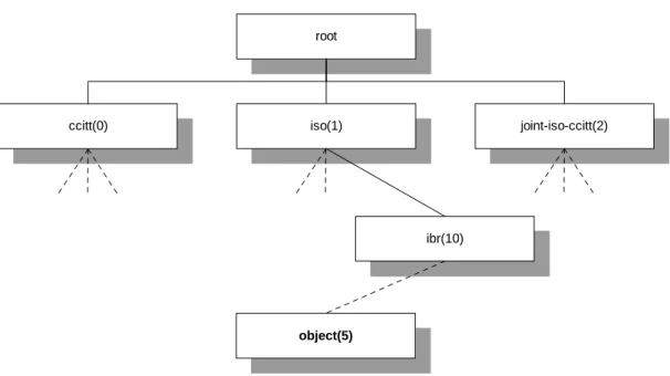
Each object defined in a MIB is identified by an object identifier, or OID, that locates the object within the standard MIB tree. An OID is normally written in dot notation beginning with the root of the MIB tree. Each branch of the tree is assigned a unique numeric value as well as a name, so both are commonly seen when representing OIDs. Figure 2 gives an example of a MIB tree structure and this naming scheme.
root
iso(1)
ccitt(0) joint-iso-ccitt(2)
object(5)
ibr(10)
Figure 2. Standard MIB tree structure. The ISO and CCITT organizations each manage one branch of the tree, and the third branch is jointly administrated. The OID of the object in bold above is written as “ iso.ibr. … .object” , or “ 1.10. … .5”
used.
Below is an example of a typical MIB object definition in ASN.1 syntax:
sysContact OBJECT-TYPE
SYNTAX DisplayString (SIZE (0..255))
ACCESS read-write
STATUS mandatory
DESCRIPTION
"The textual identification of the contact person for this managed node, together with information on how to contact this person."
::= { system 4 }
MIB object definitions can also contain sequences of nested objects, allowing more complex data structures to be created.
6.1.2 MIB Usage
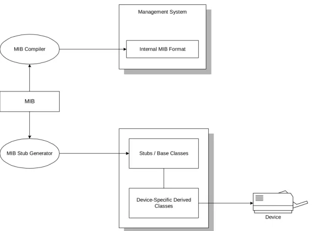
Once a MIB file has been defined for a device, it has two distinct uses which are illustrated in Figure 3. Most management packages include a MIB compiler, which
Table 1. MIB object definition properties.
Name Description
Name A name that identifies the object among its siblings in the overall MIB tree. Type The data type of the value represented by the object. The SNMP standard supports a number of standard data types, including integer, string,
counter, etc.
Access The access privileges of the value. Possibilities include read-only, read-write, write-only, etc. Description A user-readable description of the object.
converts an ASN.1 syntax MIB file into the internal format used by the management system. Thus, a MIB file is normally imported into any number of management systems to make it available for use.
The MIB must also be closely correlated with the proxy agent implementation for the device. Since managers use the object identifiers found in the MIB to query and set values, these exact object identifiers must be made available by the proxy agent. The most effective way to maintain this correlation is to use another form of MIB compiler to generate stub functions that can be implemented by the proxy agent developer. This
Management System
Internal MIB Format MIB Compiler
MIB Stub Generator
MIB
Stubs / Base Classes
Device-Specific Derived Classes
Device
Figure 3. MIB usage in SNMP. A MIB is normally compiled into both an internal format for management software, as well as a set of base classes for proxy agent
base classes based on the objects in the MIB. These base classes contain get/set methods for each object’s data type based on the access privileges in the object definition. Proxy agent developers can then derive from these base classes to implement device-specific functionality. This method is employed by the JAX architecture [10] used in this research, which provides an abstraction of the details of SNMP.
6.2 Protocol Specifics
Using the object definitions found in the MIB, the proxy agent for a device has the ability to create instances of these objects. For instance, in the printer example described earlier, a MIB might contain an object definition for a media tray. Once the proxy agent is online, it might instance one of these objects for each media tray found on the device. Managers work with instances of MIB objects. These instances are referenced by the OID of the object in the MIB followed by an index number identifying the instance.
The SNMP protocol supports only a small set of commands (hence keeping the protocol “ simple” as the name suggests). The following is a representative list of the commands found in the protocol:
• GET [oid]
• GET-NEXT [oid]
• SET [oid] [value]
The GET and SET commands are straightforward, allowing simple access to variables based on an object identifier. The GET-NEXT command is provided so that managers can easily iterate through a sequence of object instances without knowing a priori how many instances exist. A manager can issue a GET command on instance 0 of an object and continue issuing GET-NEXT requests until an appropriate error code is returned from the proxy agent. A TRAP or NOTIFICATION provides a means for agents to send messages back to listening managers.
6.3 MIB Data Structures
Tables are the most common form of complex data structure found in a MIB.
Although much more complicated data structures are allowed (implementations of hash tables exist), management packages rarely support them. In general, device
manufacturers tend to define only what common management packages support by default, since this makes their device easier to manage in the most software.
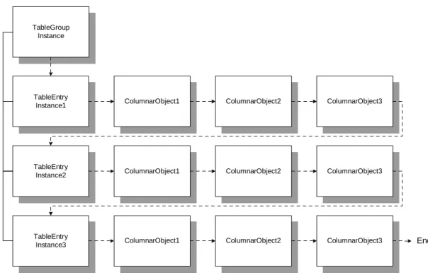
Tables are defined by constructing a table entry object that contains a sequence of other objects. Each table entry object corresponds to a row in the table, while each object in the table entry’s sequence corresponds to a column. By instancing multiple table entry objects, a table can be created. Managers can then issue GET-NEXT requests over the table entries to gather data for the entire table. Figure 4 illustrates this process.
Tables are generally used in MIB definitions for a static set of elements that have related values. For instance, a routing table would be common in network management (and is, in fact, defined in the SNMP standard MIB).
From a software perspective, building a hierarchy of tables seems like a useful technique for MIBs to support. However, although the structure itself is not precluded in SNMP, nesting of tables is not commonly supported by management software. The best alternative is an indexing scheme similar to relational database implementations [11].
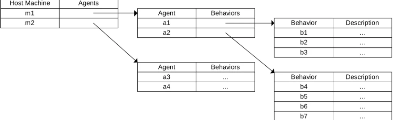
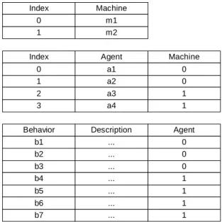
Consider representing the components of an agent platform with nested tables. At the highest level might be a table of host machines, where each host machine contains a table of agents running on that machine, and each agent contains a list of behaviors that are currently running on each agent.
TableEntry
Instance1 ColumnarObject1 ColumnarObject2 ColumnarObject3
TableEntry
Instance2 ColumnarObject1 ColumnarObject2 ColumnarObject3
TableEntry
Instance3 ColumnarObject1 ColumnarObject2 ColumnarObject3 End
Figure 4. Table structure in SNMP. Tables are created by instancing multiple tableEntry objects to create rows of the table. Managers can iterate through the table by starting at the first row object and issuing GET-NEXT requests until the last object in the last row is reached. Dashed lines indicate the sequence of GET-NEXT requests, and solid lines indicate the actual connections between objects.
Figure 5 shows the ideal representation for this structure, and Figure 6 shows the alternative structure that would be used in an SNMP MIB.
Due to the lack of management software support for such a structure, however, this definition is not reasonable. Tables, in general, are meant to display a static set of
information where only the values in the table change from time to time. Polling takes place on the values within the table, not on the rows of the table itself. Managers are typically not equipped to deal with tables that add and remove rows constantly. (Much of this is likely historical – in network management, routers do not appear and
disappear from a network at a high frequency.)
6.4 Notifications
Notifications are just another object definition within a MIB, except that they are flagged as a notification so that management software is prepared to receive
asynchronous broadcasts of these objects. Notifications are generally a sequence of
Host Machine Agents
m1 m2 Agent Behaviors a1 a2 Agent Behaviors a3 ... a4 ... Behavior Description b1 ... b2 ... b3 ... Behavior Description b4 ... b5 ... b6 ... b7 ...
Figure 5. Nesting of tables in a MIB structure. Intuitively, this structure makes sense for some sets of data, but it is generally not supported in management software that interprets SNMP MIBs.
objects providing more detailed information about the event. A specific port on the management machine is dedicated to listening for notifications from proxy agents.
6.5 Trigger Variables
Often, it is necessary for a manager to signal a proxy agent to perform some action that is more complex than just setting a new value for a variable. For example, a printer might need to have its queue flushed after some error occurred. For this purpose, this research defines trigger variables to be variables that, when set to a specific value, signal the proxy agent to perform a given task. These variables are normally either Boolean or numeric variables where the values have special meaning. For instance, a printer MIB might have a printerFlushQueue variable that defaults to 0, but when set to 1 triggers the printer proxy agent to flush the print queue.
1 a2 Behavior Description b1 ... b2 ... b3 ... 0 2 a3 3 a4 1 1 Agent 0 0 0 b4 ... b5 ... 1 1 b6 ... b7 ... 1 1
7. THE AGENTSNMP SYSTEM
The goal of this research is to provide a formal method of managing agent platforms using a network management paradigm. This solution can then be used in currently available industry-standard enterprise management products to test its viability.
With this goal in mind, the AgentSNMP management system is developed in this work. With the similarities between networks and agent platforms described above, a centralized network management scheme can be applied to manage the agent platform. In this case, the managed resource is the agent platform itself (and all of the host
machines that it encompasses), and proxy agent(s) provide a standardized view of the agent platform to management systems. SNMP is used as the management protocol in the system.
Although decentralized management has some advantages, centralization is still the industry standard, and many sophisticated management systems are available that support it. Thus, a centralized scheme has been chosen for this research.
This research is based on the FIPA agent platform specification [1]. The FIPA specification is the most popular in terms of agent platform specifications, and it
provides a solid agent platform definition that can be easily used to form a management solution. The research uses the JADE implementation of this specification as a prototype for the management system.
• Implementation of a proxy agent that exposes this interface and can communicate via SNMP.
• Integration of the proxy agent with a number of management systems, including customization where necessary to take advantage of application-specific
management capabilities.
• Testing the system with generalized, pattern-based agent scenarios.
The result of this research is an agent-platform independent, extensible agent management system that can be used with currently existing, widely used management software.
8. ARCHITECTURE OVERVIEW
This section gives a high-level overview of the AgentSNMP architecture. Each of the components’ designs will be described at length below.
The management system can be logically partitioned into three layers:
• Agent platform-specific proxy agent layer
• AgentX SNMP layer
• Management system layer
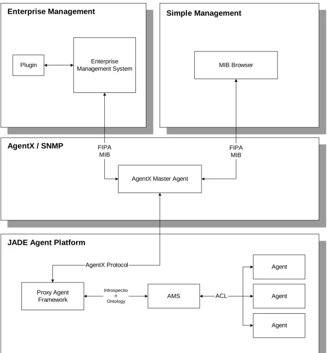
Figure 7 shows the high-level architecture for the JADE agent platform implementation of the AgentSNMP system.
8.1 Agent Platform Layer
Beginning with the lowest layer in Figure 7, the agent platform layer provides the core management functionality of the system. The main component is the proxy agent framework, which provides the central communication mechanism between the agent platform and any listening managers.
Enterprise Management
AgentX / SNMP
JADE Agent Platform
Simple Management
AgentX Master Agent
MIB Browser FIPA MIB Enterprise Management System Plugin FIPA MIB Proxy Agent Framework AgentX Protocol AMS Introspectio n Ontology Agent Agent Agent ACL
For the JADE implementation of AgentSNMP, the proxy agent is an actual FIPA-compliant agent living in the platform, allowing it to have full access to platform events. Agents in the JADE platform can register themselves as “ tools” and are thus given access to more diagnostic information than other agents. Subscribing as a tool agent as well as using the introspection ontology allows most important system events to be received.
The proxy agent is responsible for communicating with both the AgentX [12] master agent, which hides details of SNMP from the proxy agent, as well as the agent platform itself. In JADE, since the proxy agent is registered as a tool, it receives events from the AMS when various actions occur within the platform. The proxy agent must maintain some amount of state to be able to return information to managers asynchronously from these events. This agent will also send traps to the master agent when agents are created, destroyed, etc.
Note that this part of the implementation is extremely platform-specific. The means by which a proxy agent obtains information from its resource depend almost completely on how the resource makes that information available. For instance, in the JADE
implementation, tool agents can receive platform-level events, but the concept of a tool agent might not even exist in another platform (since it is not a FIPA concept). A key element to this design is the layering structure that allows for completely different internal implementations to exist provided that they expose the interface defined by the MIB.
an off-the-shelf solution. The AgentX specification is well specified and used throughout the industry as an technique for writing custom SNMP-based proxy agents.
Obviously, this layer could be avoided by pushing the SNMP implementation into the proxy agent itself. However, this unnecessarily complicates the proxy agent and leaves the proxy agent implementation prone to errors. The AgentX design hides a large of amount of SNMP details that are not wise to reimplement when a proven
implementation exists.
8.3 Management Layer
The top layer in the system is the management system. In the simple case, the management system will be a standard MIB browser that can be used to manipulate variables exposed through the proxy agent.
As discussed earlier, an enterprise management system provides more sophisticated management support as well as customization capabilities. The management system connects to the AgentX master agent and polls for values over time, checking user-defined thresholds. A plugin component will be written for the management system that allows more effective visualization of the agent platform when these thresholds occur.
9. FIPA MIB DESIGN
The first step in designing an SNMP management solution for agent platforms is to design a MIB that facilitates all of the management requirements described earlier. This section discusses the design and structure of the FIPA MIB in detail.
9.1 Design Considerations
The FIPA MIB acts as an interface for managers to the agent platform and thus controls all access to information and functionality within the platform itself. Although it is not reasonable to provide all possible information about the platform such that every management need is satisfied, the interface serves as a baseline for the most common management information. Specific implementations can add more platform or agent -specific information as needed.
In addition to the set of management requirements discussed earlier, a few main goals were kept in mind when designing the MIB for an agent platform:
• The MIB must allow easy and efficient access to core agent platform information, meeting the requirements listed above for managing an agent platform.
The second bullet in this list presents the biggest challenge in designing the MIB for FIPA agent platforms. Traditional network management is not a very dynamic problem in terms of the structure of the nodes to be managed. Network components may change over time, but generally not at a high frequency. Typically, a network management package runs a “ discovery” phase on initialization that queries the network extensively to search for new nodes. (This search can take many hours for a large network.) Once a logical map of the network is constructed, proxy agents make the values for each node available that can be polled/changed. If new nodes are added to the network, this “ discovery” step must be run again to pick up the change, which can be another long delay depending on the package used. Nodes can also be added manually for quick access without running the discovery phase again, but the user must know the specific address or location of the node. Normally, a large discovery update would be run at night to pick up large topological changes in the network.
On agent platforms, however, the situation is quite different. Agents can be created, destroyed, and migrated at rapid rates. This implies that a traditional discovery
technique is not a suitable approach.
9.2 MIB Specification
• A small set of singleton objects giving general, global information about the platform.
• A set of tables providing information about elements in the platform.
• A set of notifications used to inform managers about changes to the tables asynchronously.
This MIB design uses notifications to inform managers asynchronously of topological changes in the agent platform (i.e., agent creation, deletion, etc.) Each
notification contains a small set of core information about the change. Managers that are interested in a particular change can use the corresponding table that relates to the notification to retrieve more extensive information about any change that occurred.
Theoretically, notifications are not necessary for the management goals to be met. Managers could poll the contents of each table and keep track of changes, but this strays from the traditional network management approach greatly. It would also generate a large amount of needless network traffic involved in retrieving the entire contents of each table at an intermittent rate.
Table 2 shows the high-level format of the FIPA MIB. Each of the individual MIB objects is described in detail in the Appendix.
9.3 Levels of Analysis
In addition to the basic set of information about each agent, each row of the agent table described above introduces the concept of analysis levels for an agent. These variables allow a manager to set the management granularity of individual components of an agent. For instance, if a manager is not interested in the behaviors running on a
particular agent, it can set the behaviorAnalysisLevel to 0, indicating that no extra time will be spent keeping track of behaviors running on that agent. Reducing analysis levels reduces the number of notifications sent by the proxy agent and hence the amount of memory and processing time needed by the proxy agent to keep track of information.
One of the most common reasons for reducing the analysis level on an agent is to reduce the number of notifications that a manager will receive. There are numerous reasons for doing so, including the following:
• The management software is not capable of supporting user feedback for the notifications. For instance, consider a simple MIB browser application that allows basic get/set operations on MIB values. It would not make sense to notify this application every time a message is sent from one agent to another.
count, etc.
AgentTable A table of agents running on the platform. Each row in the table represents an agent and the attributes available for getting/setting values associated with that agent.
BehaviorTable A table of behaviors currently running on the platform. Each row in the table represents a behavior running on an agent in the agent table.
MessageTable A table of recent messages transmitted on the platform. Each row contains information such as the sender, recipient, content size, etc.
ChannelTable A table of channels currently active on the platform. Channels are an abstraction of individual messages that aid in communication pattern analysis. Each row in the table contains information such as the number of messages transmitted through the channel in each direction, the rate of messages being transmitted, and the most common performative used in each direction.
CreatorGroup A set of objects used to create new elements on the platform, such as new agents.
Notifications The set of notifications that can be sent from the proxy agent to listening managers. This includes such events as agentCreate, agentDelete, etc.
• The number of notifications would overwhelm the network itself. For a particularly busy agent, notifications of behavior state changes and messages might consume not only the management software but potentially the proxy agent and the agent platform itself. (This point is discussed in more detail in section 13).
In general, the analysis levels on an agent should be set to the minimum level possible. Reducing the analysis levels on an agent can significantly improve the performance of both the management system and the agent platform.
9.4 Channels
One of the requirements in managing an agent platform discussed previously was the ability to analyze patterns of agent communication. Even though individual message tracking provides a low-level means of meeting this requirement, a higher-level method seems appropriate.
9.4.1 Definition
A channel is defined in this research as an abstraction over the set of messages sent between two agents. A channel exists between every pair of agents that is
communicating and contains information such as the number of messages sent from one agent to the other and the rate at which those messages were sent. Thus, channels
provide a higher-level means of tracking communication between agents.
Conceptually, think of a channel as a pipe through which agents can communicate. One agent sits at each end of the pipe, and messages pass through the pipe in both
The FIPA MIB contains a table of channels currently active within the platform. A new channel is created between two agents as soon as a message is sent between them in either direction. If either agent is destroyed, the channel is destroyed as well.
9.4.2 Channel Example
By analyzing channels instead of individual messages, a manager can more easily observe the patterns underlying the individual messages being sent in the platform.
For instance, consider a communication pattern in which a message originates from a host agent (agent 0) and is passed from one agent to another until the host receives the message back. Once this happens, the host sends a new message following the same pattern. Analyzing the low-level message traffic after two iterations of this pattern, the message table would appear as shown in Table 3.
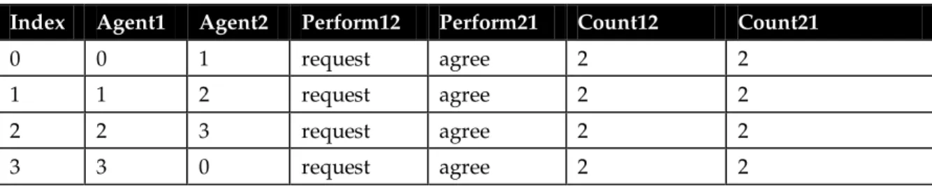
It is not immediately obvious what is happening from this table. After closer inspection, the pattern becomes clear. However, it is easy to see how a more complex pattern would make this method of communication analysis difficult to use. Consider the same information presented in a channel table as in Table 4.
Agent0 Message Channel Message Agent1
Table 3. Message table entries for message routing scenario.
Index Sender Recipient Performative Content
0 0 1 request … 1 1 0 agree … 2 1 2 request … 3 2 1 agree … 4 2 3 request … 5 3 2 agree … 6 3 0 request … 7 0 3 agree … 8 0 1 request … 9 1 0 agree … 10 1 2 request … 11 2 1 agree … 12 2 3 request … 13 3 2 agree … 14 3 0 request … 15 0 3 agree …
Table 4. Channel table entries for message routing scenario.
Index Agent1 Agent2 Perform12 Perform21 Count12 Count21
0 0 1 request agree 2 2
1 1 2 request agree 2 2
2 2 3 request agree 2 2
next to them in the platform.
Ideally, a manager would present this information visually as in Figure 9. Here, channels are represented by lines between agents, and the most common performatives used in each direction through the channel are shown. The number of messages is also shown next to the performative. (The performative closest to an agent implies that the performative was used in messages originating from that agent.)
Obviously, channels are only meaningful in some situations where there is a clear pattern. In fact, they can be deceiving if relied upon too heavily. A user should make use
1
reque st(2) agree (2) agre e(2) requ est(2 )0
2
3
ag ree (2) reque st(2) requ est(2 ) agre e(2)Figure 9. Graphical representation of channels between agents. Performatives are shown next to the agent that originated messages with that performative most.
of both channels and lower-level message tracking to fully analyze communication between agents.
9.5 Use of Notifications
The FIPA MIB relies heavily on notifications to inform managers of changes to table content. The intent of the majority of these notifications is to encapsulate the minimum context for a listening manager to respond appropriately. In many cases, this may mean a manager must query a table in the MIB for additional information after receiving a notification. (For instance, if a manager receives a behaviorAdd notification, it may need to query the table of behaviors to find more information about the particular behavior that was added, since not all information about the behavior is included in the
notification.) This reduces the size of the notifications and allows managers full flexibility in retrieving only the information they require for each type of notification.
9.6 Creation Groups
To facilitate basic object creation on an agent platform, a number of creator objects are defined in the MIB. These function as extensions to the basic trigger variable functionality described earlier. In the case of agent creation, for example, one variable cannot provide all of the information necessary to create a new agent of a given class. Thus, the MIB assumes that the necessary dependent variables are set before the trigger variable is set. In the case of agent creation, the display name, class name, and host index must all be set before the trigger variable is set.
agents run. It does not specify if an agent platform should be one machine or many, how to design concurrent activity among agents, etc. These issues are left to the designer of the implementation.
However, from a management perspective, many of these implementation details need to be exposed. Since the MIB definition above is meant to be compliant with any FIPA implementation, these “ details” are presented in the most generic means possible. It is up to the proxy agent designer to correctly map these generic attributes of agent platforms to the implementation being used.
For instance, a host table exists in the MIB to present managers with a view of how many host machines are being used on the platform. This is necessary to ensure that one machine’s resources do not become overloaded.
Mapping this host table interface to the specific implementation of an agent
platform may not be direct. For example, the JADE implementation uses the concept of a container, which normally maps to a host machine but does not have to. Multiple
containers may exist on one host machine, meaning that the proxy agent for JADE will need to take this into account when entering values into the host table. Other
implementations might only use one machine, in which case the host table would only have one entry.
Overall, these generic additions should be straightforward to implement in proxy agents, but care should be taken to map them properly to specific implementations.
10. PROXY AGENT DESIGN
As mentioned earlier, the proxy agent is responsible for implementing a set of interfaces defined in the MIB and accepting requests from management software. This chapter describes the design and implementation of the proxy agent for the JADE agent platform implementation, the prototype agent platform for AgentSNMP.
JADE provides a number of mechanisms for retrieving platform events, but almost all of them require that the recipient of those events be an agent living in the platform. Thus, the proxy agent is in this case a mobile agent running on the platform itself (as opposed to an external process that is watching activity on the platform). This design choice may not be necessary on other FIPA-compliant agent platforms.
10.1 Implementation Overview
The implementation of the proxy agent for the JADE platform is fairly straightforward. Upon initialization, the following actions occur:
• The proxy agent registers itself with the AMS as a “ tool,” allowing it to receive information about platform-specific events. It also registers several management ontologies so that it can request platform changes and communicate with the AMS correctly.
started when the platform was initialized.
Following initialization, the proxy agent waits for either SNMP requests coming from the master agent or platform events from the AMS. Responding to these two types of events makes up the core functionality of the proxy agent.
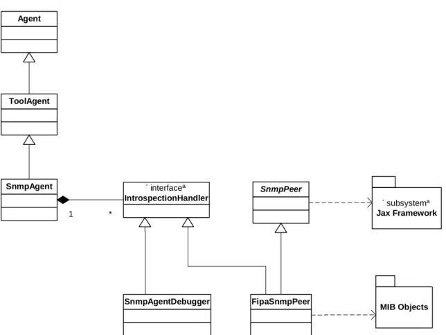
Figure 10 shows the class structure of the proxy agent implementation. The SnmpAgent and FipaSnmpPeer classes are the central components of this structure. Additional classes are summarized in Table 5.
10.1.1 SnmpAgent
The SnmpAgent class is an actual FIPA-compliant agent living on the platform that is being managed. Creating an SnmpAgent enables SNMP management capabilities on the platform where the agent is created.
The main responsibility of the SnmpAgent class is to handle communication with the AMS. This communication includes both accepting platform event messages as well as sending requests. For instance, when platform events occur such as agent creation, deletion, or migration, the SnmpAgent is notified since it is registered as a tool agent with the AMS.
Table 5. Description of class functionality in AgentSNMP.
Class Description
SnmpAgent A FIPA-compliant agent living on the platform that is being
managed. Listens for platform-level events and sends requests to the AMS.
SnmpPeer Hides JAX-specific functionality and encapsulates starting a session
with SNMP. Also sends notifications to listening managers. FipaSnmpPeer Maintains the FIPA-specific set of MIB objects for the proxy agent.
Translates platform events to MIB data changes, normally involving table modifications and/or notifications.
SnmpAgentDebugger Handles enabling/disabling “ debugging” on a per-agent basis, which JADE requires for receiving low-level platform events such as message send/receive. SnmpAgent «interface» IntrospectionHandler FipaSnmpPeer SnmpPeer «subsystem» Jax Framework SnmpAgentDebugger 1 * MIB Objects ToolAgent Agent
implementations of the generated MIB base classes and registers them through the SnmpPeer base class.
The FipaSnmpPeer class plays a translation role in the proxy agent framework. It receives notifications of all platform events from the SnmpAgent through the
IntrospectionHandler interface. It is responsible for translating these events into their appropriate SNMP responses, usually meaning a modification to a MIB table and/or sending a notification to listening managers.
10.2 Interaction with JAX Framework
Since this research is not meant to be an exercise in implementing SNMP from scratch, the AgentX architecture [12] is used to provide SNMP support. AgentX acts as a server for SNMP requests from managers. Subagents can register with a master agent (or the AgentX server) and communicate through a standard API, thus relieving the developer from knowing the details of SNMP. AgentX is used commonly for software-oriented proxy agent development, where SNMP details can be separated from the actual proxy agent implementation.
The JAX [10] implementation of the AgentX architecture is best suited for this research, given its ability to compile MIB definitions directly into native Java code, which fits nicely with the JADE framework.
Using the JAX framework, the FIPA MIB described above is compiled into a set of base classes that represent the objects found in the MIB. These classes are registered via the SnmpPeer class so that managers will be able to query/set values in them.
The JAX framework handles SNMP requests by translating the low-level SNMP protocol requests into higher-level function calls on these MIB objects. As an example, consider the MessageGroup object in the FIPA MIB. The JAX compiler creates a MessageGroup class that stores the variables contained in this group, namely, the messageTableMaxSize and messageTableStoreContent variables. Now, suppose a SET
request arrives for the value of the messageTableMaxSize parameter in the MessageGroup object. The default implementation that JAX generates through the compiler is to simply store the new value for the variable. However, by deriving a MessageGroupImpl class from the generated base class, the proxy agent implementation can perform necessary actions on the message table based on the new maximum size. This functionality is illustrated in Figure 11.
Most of the JAX-generated classes have a corresponding derived class (ending in an “ Impl” suffix). The only exceptions are the notification objects, which do not need to be modified since they are outgoing messages. Table 6 summarizes the functionality in each of the derived classes.
10.3 Object Interactions
As an example of how the proxy agent classes interact, consider as an example a new agent being created on the platform. Because the SnmpAgent is registered as a tool, the AMS notifies the SnmpAgent with a message indicating the creation of a new agent.
Master Agent MessageGroupImpl MessageGroup Jax S E T setMessageTableMaxSize()
Perform necessary actions to adjust message table size.
T
Figure 11. Example of an SNMP request originating from a manager. The JAX framework translates the SET request to a function call to the appropriate MIB object.
Table 6. Compiler-generated MIB base classes and corresponding derived classes.
Base Class Derived Class Description
AgentCreator AgentCreatorImpl Creates a new agent upon receiving a set request on trigger variable.
AgentEntry AgentEntryImpl Migrates agent on receiving set request for host index. Kills agent on receiving set request for agentAlive variable.
Sets agent state on receiving set request for state variable.
Handles changes to load analysis level modifications. BehaviorEntry BehaviorEntryImpl Derived to set read-only variables within the class. ChannelEntry ChannelEntryImpl Derived to keep track of message counts/rates
through the channel.
ChannelTable ChannelTableImpl Derived to provide methods for finding existing channels between two agents.
HostEntry HostEntryImpl Kills host on receiving a set request on hostAlive variable.
Handles requests for available host memory. MessageEntry MessageEntryImpl Derived to set read-only attributes of object.
MessageGroup MessageGroupImpl Derived to handle changes to maximum message table size.
The SnmpAgent then distributes the message to the FipaSnmpPeer for translation to SNMP.
Upon receiving notification of the new agent, the FipaSnmpPeer class creates a new AgentEntryImpl object that represents the agent in the MIB. (Remember that this new object will also handle any incoming SNMP requests for that agent.) The FipaSnmpPeer object then sends an AgentCreate notification to listening managers. Figure 12 illustrates this behavior.
10.4 Thread Communication and Control
The SnmpAgent contains two concurrent threads accessing data in the agent and its component classes. One thread is part of the JAX framework and waits for SNMP
requests to come through a specific network port from the master agent. The other is the agent scheduling thread that runs the agent behaviors in round-robin fashion on the JADE platform.
Generally, the types of SNMP requests that arrive on the JAX thread can be broken up into two categories:
• Read-only requests that require no action from the SnmpAgent itself. Data are read directly from a table or variable and returned.
• Requests that trigger some sort of request that the SnmpAgent must respond to. This second type of request causes some issues in managing communication between the two threads. The SNMP request coming from the JAX thread needs to wait before returning for the appropriate action to occur, so that it can return an error code if something unexpected happens. The JADE scheduling framework breaks down if