654
Transient Stability Analysis Of Grid Connected
DFIG Based Wind Turbine With FRT Controllers
A.Mabel Jemima, Dr.J.Preetha Roselyn,CR Ragahavendran
Abstract: The increasing penetration of wind power in power system has created many stability issues in the electrical grid. More conventional power plants are replaced by wind farms and accordingly the stability of the power system will be affected. During grid faults, the voltage at the point of common coupling faces major dip and the wind system gets disconnected from the grid and the hence the system faces difficulty to return back to normal state after the fault is recovered. To avoid this disconnection of wind systems during faults, a PQ based Fault Ride Through controller is proposed in this paper. This controller injects reactive power into the system depending upon the level of the voltage drop during faults thereby improves the transient performance of the system. The proposed controller improves the system parameters of grid connected wind systems in accordance with grid code compliance. The proposed model is implemented and validated in 40 MW grid connected DFIG based wind system in Digsilent software.
Index Terms: DFIG, Fault Analysis Fault Ride Through(FRT), PQ controller ,Voltage dip,Voltage at PCC
—————————— —————————
I.
INTRODUCTION
Among various renewable energy sources wind energy is considered to be significant because it has higher efficiency than other renewable sources. Several developments are being adopted in the wind energy sector so as to make it capable of being a single source of energy providers for industrial sectors. Current wind turbines are high sized serving in mega-watts. India ranks 5th in the world in wind energy production. According to the data on 31st march 2019 India has a total wind energy generation capacity of 36.625 GW. Although it is considered as an uncertain source of energy the developments that has been made via the implementation of controllers both on the RSC and GSC side is proving wind to be a stable source of energy. The transient stability analysis of the wind turbine has been done by the construction of the wind system DigSilenT software and then making it experiencing a fault. During this fault occurrence a voltage dip occurs which causes the disconnection of the system from the grid. Thus a PQ controller has been implemented in the rotor side of the system which injects the reactive power thus making improvements in the voltage levels which ensures that system remains connected with the grid thus making the system fault ride through capable. H.Aliabadi [1] et al proposed a basic breaking resistor and SVC for the reactive power compensation and is very less effective. Yazan M et al [2] proposed the vector control technique for the same objective but the entire analysis is made in synchronous reference made it did not provide much accuracy. Zhisheng Xu [3] proposed the implementation of the filters which suppressed harmonics thereby injected reactive power, but it produced random values for the amount of the reactive power that has been injected so it doesn’t produce accurate results. Chao Liu [4] et al proposed the use of PLL which will act as frequency locker, but it was not able sustain heavy faults such as three phase symmetrical faults so a much developed PQ controller has been implemented here to provide stable active and reactive power throughout the system. A.O Aluko [5] et al proposed the implementation of the STATCOM but obviously implementation of the FACTS devices made the system costly. Dipesh .M et al [6] proposed the usage of VSATCOM and compared the voltage from VSC. If the voltage of VSC is higher or lower VSTATCOM will act accordingly. But this is
not specific about the amount of reactive power that has to be injected.
Yuzhi Wang [7] et al proposed the usage of STATCOM and SSCI t seemed to be effective but regulation of reactive power was bit complicated. Yasoda k [8] et al proposed the calculation of Qmargin at all buses and proposed the implementation of STATCOM at the weakest Qmargin bus. But it doesn’t seem to co-ordinate well in-case of external disturbances that occurs. Mohamed H. Hassan et al [9] proposed the objective of designing a Grid connected Wind system in DigsilenT software and implemented a basic PQ controller which further requires an additional SATCOM for the injection but this made the system complex and costly. Thus this system proposes an ideal PQ controller for the injection of the reactive power. The system is analysed under normal and under fault conditions while the system being connected to the grid .Occurrence of fault causes a dip in voltage which further results in disconnection of the wind from the grid. To avoid this disconnection, voltage is made to sustain at rates by the PQ-FRT controller. Thus the system was studied during fault condition without and with PQ controller. By these observations as with and without controller active power, reactive power and voltage at PCC are stabilized The controller was made to act in a way such that the dip that has been created by the fault was rectified with the help of controller at the time of fault itself. This provides constant connection of the system with the grid thus ensuring grid stability. Thereby the grid stability is improved.
II.
FAULT RIDE THROUGH CAPABILITY
655
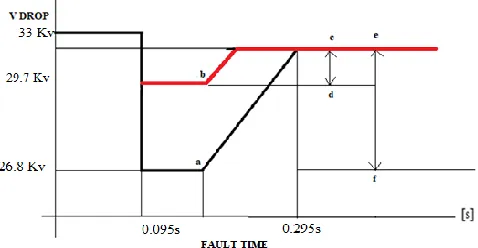
doesn’t allow the voltage to reach to point a. This is because the dip in voltage at point a represented as ef denotes the range for which the plant may get disconnected from the grid .Point b which is the range cd denotes that the voltage is made to sustain at values where the plant remains connected to the grid during fault.
Fig 1 Fault Ride through Capability curve
Thus the acceptable limits of voltage sustainability through FRT for different low voltage and high voltage buses are determined by the IEGC (C-WET data).
Fig 2 Voltage limits as per IEGC
III. DESCRIPTION AND WORKING
Fig. 3 Single Line diagram of the test circuit
Fig 3 represents the system model that was constructed in DigSilenT software. The DFIG based Wind generator of 0.69Kv is connected to a node bus of 0.69Kv where it connects the generator and rotor side converter. The rotor side converter possess four major converters namely Pitch, Shaft, Speed and PQ controllers. The rotor side and the grid side converter are connected to each other through a DC bus of rating 1.15Kv to power up the controllers that are inside the converters. The grid side converter mainly has the AC and the DC voltage controller. Thus the GSC feeds the first turbine based bus of rating of 0.69Kv. Thus through the transformer it feeds the bus of rating 33Kv, which connects the wind side and the grid side and thus denoted as Point of Common Coupling (PCC). Then the 33Kv is boosted to 110Kv further it is boosted to 220Kv which is the final grid rating. Table 1 holds the summarized data of the voltage values at all the buses.
TABLE 1 Values of voltage at buses
BUS VOLTAGE VALUE (Kv)
Wind turbine 0.69
Bus 1 0.69
Bus 2 33
Bus 3 110
Bus 4 110
Bus 5 110
Bus 6 220
The RSC and the GSC implemented in DigSilenT are shown in the Fig 4 and Fig 5
656 Fig 5 Controllers on Grid side
Speed Controller: The input is the actual speed which is the reference value and the current speed which is the real time value and the difference in the both the signals are calculated as error and given as a single value to the PI controller. The output is the total active power that is fed to the PQ controller. This input speed to the output active power is generated by a PI controller and a transfer function block. Apart from this I enable signal is given to regulate the ramp range of the speed. Pitch Controller: The inputs are same as the speed controller as speed and speed reference but this is determined in terms of beta which is nothing but the angle of the blade. Multiplied with constant 0.01 and the difference in speed and speed reference is termed as the error signal is given to the PI controller. The output is beta and after multiplying with time constant the output is beta determinant and across the two limiters after it the required beta value is obtained. Shaft Controller: The power input from the turbine which is pw is tuned in with the speed of the turbine and is fed to the transfer function block. The output of the transfer function is fed to the spring from which the rate point is determined between the actual loadability of the spring and the rate point. Thus the output of the shaft controller is the shaft controller is the rate point which is fed to the DFIG. Fig 6 shows the proposed PQ controller. It determines the range of two currents namely id and iq which in turn regulates the
limit of active and reactive power.
Fig 6 Proposed PQ controller
A synchronous reference frame PLL [7] is used in the system. It helps in maintaining the value of the voltage and power near to the rated values. The voltage that is oriented in the q axis becomes zero so that the equations become
(1)
The reference values are the values that are supposed to be the circuit’s configuration and the actual values are measured from PCC. The error signal is calculated and fed to the PI controller. The output will be the values of id and iq which controls the active and reactive power.
(2) :
(3)
AC and DC voltage controllers: As of the previous controllers the actual value and the reference values are compared and the error signal is generated. The generated error signal is given to the transfer function and voltage value is obtained and then passed through the limiters to obtain current in synchronous reference frame The same follows for DC voltage controllers with DC values.
TABLE 2 Nomenclature of PQ controller
P ref - Actual rating of active power Q ref - Actual rating of reactive power P - Measured value of P after fault Q - Measured value of Q after fault
id - Current in D axis in synchronous
reference frame
iq - Current in Q axis in synchronous
reference frame
V.
RESULTS AND DISCUSSION
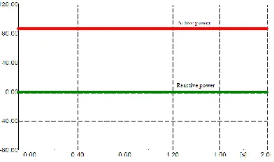
5.1-Analysis of parameters under with and without fault conditions~ As said earlier to conduct transient stability the analysis has to be made while the wind system is being connected to the grid. Transient stability analysis in case of fault occurrence was conducted and the pre fault and during fault scenarios of Voltage and power were analysed without PQ controller at PCC using DIgSILENT. A three phase symmetrical short circuit was created at 0.095 seconds and was cleared at 0.295 seconds at BUS 2 which is the PCC.
Fig 7 Active and reactive power at PCC before fault
657
Fig 8 Active and reactive power at PCC during fault
Fig 8 depicts the values of active and reactive power during fault conditions, During fault the active power dipped to 70.1 MW and the reactive power has risen up-to 4.8 MVAR due to transients but dipped to -30MVAR due to the fault.
Fig 9 Voltage at PCC before fault
After the Bus 1 a transformer rating of 0.69/33KV was implied and the voltage at bus 2 was found to be 33 KV depicted in Fig 9 which is the point of common coupling.
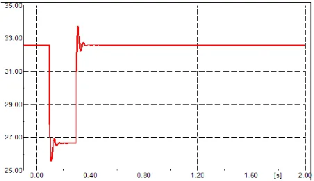
Fig 10 Voltage at PCC before fault
Fig 10 shows that during fault ,the voltage has dipped to 26.8 Kv at PCC. Thus the summarized observations of Active and Reactive power and Voltage at PCC are
TABLE 3 Values Of Parameters Before And During Fault At
PCC
Parameters Pre-fault During fault % Drop Active power 87.4 MW 70.1 MW 19.7 Reactive power 0 MVAR -30 MVAR 25
Voltage 33 Kv 26.8 Kv 18.78
Table 2 depicts the value of active power and reactive power and the voltage at PCC at pre-fault and during fault conditions. 5.2- Analysis of parameters during fault with and without PQ controllers~ The transient stability analysis has to be made while the wind system is being connected to the grid. Earlier chapter discussed about the Transient stability analysis in case of fault occurrence and the pre fault and during fault scenarios of various parameters were analysed. Now with the same fault occurrence which is a three phase symmetrical short circuit and at the same period of time of 0.095 to 0.295 seconds the analysis of parameters with and without PQ controller were analysed using DIgSilenT. The PQ controller is implemented in the rotor side converter of the circuit. It works on the principle of PQ theory. The output of the PQ controller are id and iq. id subjects for the active power
control and iq subjects for the reactive power control. The
correlation of performance between id and iq ie:- the amount
of reactive power that has to be injected with respect to the loss in the reactive power is driven by the feed forward control which works on transient current gain control method. The feed forward control is located next to the PQ controller in the rotor side converter whose output are the pulses that is fed to converter that interacts with the RSC components and the outside circuit. Thus for the same type and duration of the fault the following results were observed.
Fig 11 Active and reactive power at PCC during fault
without PQ controller
Fig 12 Active and reactive power at PCC during fault
with PQ controller
658 Fig 13 Voltage at Bus 2 during fault without PQ controller
Fig 14 Voltage at Bus 2 during fault with PQ controller
Fig 14 represents that the voltage at bus 2 during fault without PQ controller was found to be 26.8 KV which is the point of common coupling and with PQ controller the voltage has risen up-to 29.8 KV
TABLE 4 Values Of Parameters During Fault With And
Without PQ Controller At PCC
PARAMETERS WITHOUT PQ WITH PQ %
Improvement Active power 70.1 MW 87.4 MW 24.6 Reactive power -30 MVAR 40.5 MVAR 174
Voltage 26.8 Kv 29.4 Kv 11.1
Table 3 depicts the value of active and reactive power and the voltage at PCC during the fault interval with and without PQ controllers.
VII. CONCLUSION
In general the injection of the reactive power is done through the either FACTS devices or with basic level PQ controllers. They doesn’t seem to meet the reactive power requirement fully or they are costly. This work represented transient stability analysis of grid connected DFIG wind system in which occurrence of fault has caused voltage dip in the system which was then corrected with FRT controllers at the time of fault. The PQ controller that is used is quite advanced one and was able to inject reactive power as required and the voltage is made to rise up to the required values thus making the system stable. The final statement is that the system that was taken for analysis is able to persist in the voltage ranges even during fault through FRT technique so
as to remain synchronized with the grid. These voltage ranges at which the system remains synchronized with grid is given by IEGC. The future scope of the project will be fine tuning of the voltage values and implementation of Intelligent Controllers in place of PQ controller for further advancement.
REFRENCES
[1] H. Aliabadi R. Ghazi;Stability improvement of Wind Farms With Fixed-Speed Turbine Generators Using Braking Resistors; Institute of Electrical and electronics engineering ;2010.
[2] Yazan M. Alsmadi, Longaya Xu, Frede Blaabjerg; Detailed Investigationand Performance Improvement of the Dynamic Behaviour of Grid-Connected DFIG based wind turbines under LVRT conditions; Institute of Electrical and electronics engineering; Volume 54; Issue 5; pp; 4759-4812; 2018.
[3] Zhisheng Xu, Yanjian Peng, Yong Li, Min Wen, Longfu Luo, Ye Cai, and Yijia Cao, Improvement of Power Quality and Dynamic Voltage of Wind Farms Using an Inductive Filtering Method; Institute of Electrical and electronics engineering;2015.
[4] Chao Liu*, Xinshou Tian, Kai Chen, Yuanyuan Su1, Yan Li1;Effect of phase-locked loop on transient performance of wind turbines generator under voltage phase jump;Institution of Engineering and Technology;Volume 2019; Issue 16; 2018.
[5] A.O Aluko K.T Akindeji ,Mitigation Of Low Voltage Contingency;Doubly Fed Induction Generator Wind Farm Using Static Synchronous Compensator In South Africa;Institute of electrical and electronics engineering; 2018.
[6] Dipesh. M. Patel, A. R. Nagera, and Dattesh Y. Joshi ,Power Quality Improvement with Static Compensator on Grid Integration of Wind Energy System; engineering; IEEE transactions on sustainable energy;Volume 40; Issue 3; pp 450-551; 2011
[7] Yuzhi Wang, Chunhua Wang; STATCOM based SSCI Mitigation algorithm for DFIG based wind farms; Energy research and social science; Volume 12; Issue 5; pp 321-330; 2012.
[8] Yasoda.K, Devarajan.N, Veerakumar.B;Enhancement of transient stability of distribution system with SCIG and DFIG based wind farms using STATCOM ,IET Renewable Power Generation; Volume 10; Issue 8; pp 1171-1180; 2016.
[9] Mohamed Saad, Mohd Ali Tofigh, Farah Zaheeda, Ahmed N AL-Masri, Nordin Bin Othman, Design And Modeling An Automated Digsilent Power System For Optimal New Load Locations; International Journal of Scientific & Technology Research; Volume 4;Issue 8;2015.
[10]Oum el fadhelloubabaBekri ;Impact Of Wind Turbine On Voltage Stability; Institute of Electrical and electronics engineering;2018.
659
[12]Abdullah Al Mahfazur Rahman;Active and Reactive Power Control Through P-Q Controller Base System to Replicate the Behavior of Full Power Converter of Wind Turbine; International Journal of Engineering Research and General Science;2014
[13]Owolabi Sunday Adio, Xiangning Lin; Field Studies for Transient Stability in Continuous Operation and Contingency Condition During 3 – Ф Short Circuit at PCC for Grid Connected 10MW Kastina Wind Farm; Institute of Electrical and electronics engineering;2013.
[14]Yuvaraj,PratheepRaj ,Mowlidharan ,Thirugnanamoor-thy and Joshi Transacted,Power Quality Improvement for Grid Connected Wind Energy System using FACTS device; Energy Conversion and management Volume 2; Issue 3; pp 119- 130; .
[15]Mohsen Darabian1 ,AbolfazlJalilvand,Designing a wide area damping controller to coordinate FACTS devices in the presence of wind turbines with regard to time delay ; IEEE on Renewable Energy;Volume 11; Issue 9; pp 210-222; 2017.
[16]Lopes A.c, Nascimento J, Vunes M.N; Power control of direct drive synchronous wind generators to enhance the low voltage ride through capability; Renewable and sustainable energy reviews; Volume 13; Issue 7; pp; 543-551; 2010;
[17]ValmorRicardi Junior, Victor F. Mendes, Low-Voltage Ride-Through Analysis of Permanent Magnet Synchronous Wind Generator with Harmonic Distortion and Frequency Deviation using Resonant Controllers; IEEE on Renewable Energy;Volume 7; Issue 11; pp 123-134; 2017
[18]Chang-Doo Cho, Soon-Ryul Nam, Sang-Hee Kang, Seon-JuAhn, Modeling of DFIG Wind Turbines Considering Fault-ride-through Grid Code; IET Renewable Power Generation;Volume 10; Issue 8; pp 456-463; 2011.