ISSN (online): 2349-784X
A Novel Compact Rectangular Micro Strip
Monopole Antenna with U and L Slot for C-Band
Application
Bhavana Sharma Miss Bhanisha Verma
M. Tech. Student Assistant Professor
Department of Electronics & Communication Engineering Department of Electronics & Communication Engineering Haryana Engg. College, Jagadhari, Kurukhshtrya University,
Haryana, India
Haryana Engg. College, Jagadhari, Kurukhshtrya University, Haryana, India
Abstract
In this paper we are presented a small novel monopole wide band microstrip-feed antenna in which the patch is intended with a L-probe and for dual-band and multi-band application by cutting U-slots on the patch. The first notch is given frequency range from 5.4-6.0GHz, and the second notch worked on the dual frequency range of 5.0-4.8GHz and 6.0-6.4GHz, 3rd notch has in the triple band frequency range of 4.8-5GHz, 5.9-6.1GHz and 6.4-6.6GHz with very standard impedance matching.
Keywords: HFSS Simulator, Micro Strip Antenna, U-Slot, L - Probe, High Gain
________________________________________________________________________________________________________
I. INTRODUCTION
Due to the rapid growth in wireless communication, the need of multiband frequency is raising. Thus, an antenna with multiband operations is required. Multiband antennas are developed for various wireless applications so that any equipment can employ several applications. Multiband antenna plays an important part in wireless systems.
Micro strip antennas became very popular in the 1970s primarily for space borne applications. Today they are used for government and commercial applications. An Antenna (aerial) is considered as a region of transition between a transmission line and space [8].These antennas consist of a metallic patch on a dielectric substrate base on metallic ground plane [6]. Recently, micro strip patch antenna has been used in many applications, which has some merits like low fabrications weight and cost, and operating in high frequency range [1]. At microwave frequencies Micro strip slot antenna becomes very small and light weight [2]. In spite of these advantages, it has main disadvantages of low efficiency, low Return loss, narrow bandwidth and large micro strip antenna aperture size [3].
In this paper, a monopole antenna with multiband operations is proposed. This antenna operates on three different resonant frequencies 4.8GHz, 5.0 GHz, 6.0GHz and 6.4 GHz with bandwidths of 4.8-5.0 GHz, 5.9-6.1 GHz, 6.4-6.6GHz and 6.0-6.4 GHz respectively. At 4.8 GHz frequency, the antenna is used for military applications like CMOD/CMOV and small satellite earth stations applications. WLAN band is also covered by the bandwidth provided by the antenna at 4.2GHz. At 6.1 GHz, the antenna is employed for Terrestrial Microwave applications.
II. ANTENNA DESIGN & METHODOLOGY
In this paper we are presented a patch with U-shape slot with intended a L-probe to generate multiband frequency. In this design FR-4 substrate.
This antenna makes use of the finite ground plane made up of FR4 epoxy and a dielectric substrate having dielectric constant 4.4. Micro strip antennas, consist of a very thin (t<<λ0, where λ0 is the free-space wavelength) metallic strip (patch) placed a small fraction of a wavelength (h <<λ0, usually 0.003λ0 ≤ h ≤ 0.05λ0) above a ground plane. For a rectangular patch, the length L of the element is usually λ0/3 < L < λ0/2[6].
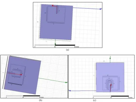
Fig.1. shows the top and the bottom view of the multi band antenna. The radiating patch is placed on a FR4 substrate material.
The substrate has the dimensions of 40 ×40 × 1.6 mm3and dielectric constant of 4.4. For the perfect impedance matching or 50-
(IJSTE/ Volume 3 / Issue 06 / 019)
(a)
(b) (c) Fig. 1:Front view (a), (b), (c) of Proposed Multiband Antenna.
The calculation of dimensions can be obtained by the following formulae: W= √(2/((ε +1) (1)
From the above formula the operating frequency can be calculated by knowing the width W and vice versa. For efficient results the effective of the dielectric constant considered, whose value is determined [5] by formula given below:
(2)
Substituting εr=2.2, W=40mm and h=0.024mm then, εreff= 2.1414. The dimensions are shown in Table I. Simulation results,
using HFSS software.
Table - 1
Dimensions of proposed antenna (UNIT: mm)
Antenna W L W’ L’ a b c d u’
A 40 40 18 22 - - - - -
B 40 40 18 22 10.8 7.5 10.8 10 0.8
Antenna W L W’ L’ a b c d b’
C 40 40 18 22 10.8 7.5 10.8 10 3.5
III. SIMULATION RESULTS
The Multiband Monopole Antenna is designed using HFSS tool. It’s user friendly software that has most accurate results. HFSS provides facility to study several antenna parameters like Return Loss, VSWR, Smith Chart and Radiation Pattern. These antenna parameters of proposed antenna are also studied in this paper. These are employed to measure the performance of an antenna. It works efficiently on three different frequencies
(IJSTE/ Volume 3 / Issue 06 / 019)
(a) (b)
(c)
Fig. 2: Return loss of proposed multiband Antenna
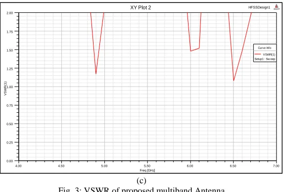
The VSWR should be near to 1 or at least less than 2 for the efficient working of the antenna. The Given Plot Represents the VSWR in the operating frequency range of the antenna. The above plot represents that the VSWR is less than 2.
(a) (b)
1.00 2.00 3.00 4.00 5.00 6.00 7.00 8.00 9.00 10.00
Freq [GHz] -30.00 -25.00 -20.00 -15.00 -10.00 -5.00 0.00 d B( S( 1 ,1 )) HFSSDesign1
XY Plot 1 ANSOFT
Curve Info dB(S(1,1)) Setup1 : Sw eep
1.00 2.00 3.00 4.00 5.00 6.00 7.00 8.00 9.00 10.00
Freq [GHz] -30.00 -25.00 -20.00 -15.00 -10.00 -5.00 0.00 d B( S( 1 ,1 )) HFSSDesign1
XY Plot 1 ANSOFT
Curve Info dB(S(1,1)) Setup1 : Sw eep
1.00 2.00 3.00 4.00 5.00 6.00 7.00 8.00 9.00 10.00
Freq [GHz] -35.00 -30.00 -25.00 -20.00 -15.00 -10.00 -5.00 0.00 d B( S( 1 ,1 )) HFSSDesign1
XY Plot 1 ANSOFT
Curve Info dB(S(1,1)) Setup1 : Sw eep
1.00 2.00 3.00 4.00 5.00 6.00 7.00 8.00 9.00 10.00
Freq [GHz] 1.00 1.20 1.40 1.60 1.80 2.00 VS W R (1 ) HFSSDesign1
XY Plot 2 ANSOFT
Curve Info VSWR(1) Setup1 : Sw eep
1.00 2.00 3.00 4.00 5.00 6.00 7.00 8.00 9.00 10.00
Freq [GHz] 1.13 1.25 1.38 1.50 1.63 1.75 1.88 2.00 VS W R (1 ) HFSSDesign1
XY Plot 3 ANSOFT
(IJSTE/ Volume 3 / Issue 06 / 019)
(c)
Fig. 3: VSWR of proposed multiband Antenna
The radiation pattern is presented with the body of the antenna so as to represent the major and minor lobe clearly. The values of the different antenna parameters obtained after the simulation has been shown below:
(a) (b)
(c)
Fig. 4: Represents the directivity of the proposed multiband antenna
4.00 4.50 5.00 5.50 6.00 6.50 7.00
Freq [GHz] 0.00
0.25 0.50 0.75 1.00 1.25 1.50 1.75 2.00
VS
W
R
(1
)
HFSSDesign1
XY Plot 2 ANSOFT
(IJSTE/ Volume 3 / Issue 06 / 019)
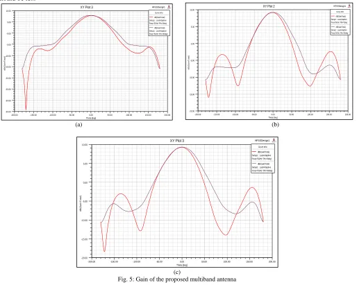
Antenna Gain
Antenna gain is calculated by directivity divided by efficiency of antenna. The variation in gain of antenna at different frequency should be less
(a) (b)
(c)
Fig. 5: Gain of the proposed multiband antenna
The impedance bandwidths and Gain are summarized in Table 2.
Table – 2
Simulated Impedance Bandwidth and Gain Antenna Simulated Frequency (GHz) Antenna Gain (dB)
a 5.42-6.02 7.98
b 4.78-4.99 9.26
6.09-6.52 c 4.81-5.00 9.34 5.94-6.10 6.40-6.60
IV. CONCLUSION
The U-slot patch antenna is mainly known for its wideband characteristics. In this letter, we show that, by combining with an L-probe feed, the use of U-slots can also yield dual- and multiband characteristics. At each frequency, VSWR < 2 shows a better impedance matching. The presented antenna can be used for WLAN, Satellite and Military Applications. The radiation parameters like Return loss, VSWR and Radiation Pattern at 4.8GHz, 5.9 GHz, and 6.1 GHz are a lso measured.
-200.00 -150.00 -100.00 -50.00 0.00 50.00 100.00 150.00 200.00
Theta [deg] -35.00 -30.00 -25.00 -20.00 -15.00 -10.00 -5.00 -0.00 5.00 10.00 d B( G a in T o ta l) HFSSDesign1
XY Plot 3 ANSOFT
Curve Info dB(GainTotal) Setup1 : LastAdaptive Freq='5GHz' Phi='0deg' dB(GainTotal) Setup1 : LastAdaptive Freq='5GHz' Phi='90deg'
-200.00 -150.00 -100.00 -50.00 0.00 50.00 100.00 150.00 200.00
Theta [deg] -20.00 -15.00 -10.00 -5.00 0.00 5.00 10.00 d B( G a in T o ta l) HFSSDesign1
XY Plot 2 ANSOFT
Curve Info dB(GainTotal) Setup1 : LastAdaptive Freq='5GHz' Phi='0deg' dB(GainTotal) Setup1 : LastAdaptive Freq='5GHz' Phi='90deg'
-200.00 -150.00 -100.00 -50.00 0.00 50.00 100.00 150.00 200.00
Theta [deg] -20.00 -15.00 -10.00 -5.00 0.00 5.00 10.00 d B( G a in T o ta l) HFSSDesign1
XY Plot 3 ANSOFT
(IJSTE/ Volume 3 / Issue 06 / 019)
REFERENCES
[1] N. A. Bimal Garg, Vijay Sharma, Ankita Tomar, Prashant Dubey, "Rectangular Microstrip Patch Antenna with "Pentagonal Rings" Shaped Metamaterial Cover," 2012 International Conference Communication Systems and Network Technologies, 2012.
[2] Zareen Aijaz and S.C.Srivastava “An Introduction of Aperture Coupled Micro strip Slot Antenna”, International Journal of Engineering Science and Technology, Vol. 2(1), 2010, 36-39.
[3] F. Y. Y. Rahmat-Samii, Electromagnetic Band Gap Structures in Antenna Engineering. United States of America: Cambridge University Press, New York, 2009.
[4] Y. Rahmat-Samii, "EBG Structures for Low Profile Antenna Designs: What Have We Learned?." New York, 2009.
[5] Neenansha Jain, Anubhuti Khare and Rajesh Nema “E-Shape Micro strip Patch Antenna on Different Thickness for pervasive Wireless Communication”, International Journal of Advanced Computer Science and Applications, Vol. 2, No. 4, 2011.
[6] C.A.Balani, “Antenna Theory analysis and design” Chapter 14, 3rd Edition, A JOHN WILEY AND SONS, INC., PUBLICATION, 2005.
[7] P. Subbulakshmi, R.Rajkumar, “Design and Characterization of Corporate Feed Rectangular Microstrip Patch Array Antenna”, IEEE International Conference on Emerging Trends in Computing, Communication and Nanotechnology (ICECCN 2013).
![Fig. 2: Return loss of proposed multiband Antenna (c) Freq [GHz]](https://thumb-us.123doks.com/thumbv2/123dok_us/7809427.1662393/3.612.57.560.46.422/fig-return-loss-proposed-multiband-antenna-freq-ghz.webp)