483 |
P a g e
THE COOLING SYSTEM OF PHOTOVOLTAIC MODULE
AND THEIR EFFECTIVE EFFICIENCY
1
Mr.Govendra Sherkar,
2Mr. Amit Akkewar
1
Department of Electrical Engineering, Gondwana University,
R.C.E.R.T, Chandrapur, Maharashtra,(India)
2
Assistant Professor, Department of Electrical Engineering,
R.C.E.R.T, Chandrapur, Maharashtra,(India)
ABSTRACT
Solar energy is one of the energy which can be use in various forms like solar lamps, solar cookers etc. For that purpose PV panel is required. Each module is related by its dc output power under standard test conditions (STC) and typically ranges from 100 to 320 watts. In this project, photovoltaic panel were used to integrate the extraction of light energy and thermal energy. The need of this project is to study of thermoelectric cooling effect to remove heat in the photovoltaic. The use of thermoelectric cooling system improves the power capacity of photovoltaic by 2%-20% and enhances the power efficiency of the photovoltaic by 2.29%-3.37%. Through the combine application of photovoltaic and thermal technologies, the total energy of the overall system can be improved by 37%-60%.
Keywords - Efficiency, solar voltage Thermoelectric Energy Conversion, Thermoelectric module,
Temperature sensor.
I. INTRODUCTION
Recently, human being required different types of energy demand and which increases rapidly. Due to use of
conventional energy (nonrenewable energy).The energy gets crises for useful structure. Due to increasing of
population the energy demand also increases and the graph of non renewable energy sources get decreases. The
solar energy is the renewable energy source and it is easily available in nature. It is also the most important
renewable source energy and it is free from pollution, it also helpful to decrease the green house effects. In this
paper, solar system is one of the ways to generate electricity through directly of the sun rays, so due to sun
energy we generate electricity and heat also. The output of PV system depends on solar irradiance, operating
voltage due to high and low temperature. The conversion efficiency of ideal solar panel is 18% due to its quick
heating property the efficiency is less therefore to increase efficiency we use thermoelectric module .Following
484 |
P a g e
1.1. Peltier (Thermoelectric) History
Early 19th century scientists, Thomas Seebeck and Jean Peltier, first discovered the phenomena that basis for
the today’s thermoelectric industry. Seebeck found that if you placed a temperature gradient across the junctions
of two dissimilar conductors, Electrical current would flow to Peltier, on other hand, learned that passing current
through two dissimilar electrical conductors, caused the heat to be either emitted or absorbed at the junction of
materials. It was only after mid-20th Century advancements in Semiconductor technology; however, those
practical applications for thermoelectric devices became feasible. With the modern techniques, we can now
produce thermoelectric “modules” that deliver efficient solid state heat-pumping for both cooling and heating;
many of these units can also be used to generate DC power at reduced efficiency. New and often elegant uses
for thermoelectric continue to be developed each day.
1.2. Peltier (Thermoelectric) Structure
Heat absorbed at the cold junction is pumped to the hot junction at a rate proportional to carrier current passing
through the circuit and the number of couple. The semiconductor materials are N and P type because either they
have more electrons than necessary to complete a perfect molecular lattice structure (N-type) or not enough
electrons to complete a lattice structure (P-type). The extra electrons in the N-type material and the holes left in
the P-type material are called "carriers" and they are the agents that move the heat energy from the cold to the
hot junction of the area. The heat absorbed at the cold junction is pumped to the hot junction at a rate
proportional to carrier current passing through the circuit and the Number of couple. Good thermoelectric
semiconductor materials such as bismuth telluride greatly impede conventional heat conduction from hot to cold
area, and it provides an easy flow for the carriers. These materials have carriers with a capacity for transferring
more heat.
Fig.1: Peltier Structure
II.
AN OVERVIEW OF PROPOSED WORK
A new approach to thermoelectric power generation using large area of the pn junctions is presented. And which
485 |
P a g e
investigate the effect of temperature on the efficiency of a conventional solar cell and also to calculate theoverall efficiency of the system.
In this project, both hardware and software setups are used. The hardware setup consists of PV panel, peltier
module, temperature sensor, ADC, microcontroller, relay and the LCD display. With the help of hardware setup
observe the voltage drop at high temperature and low temperature and also observation of efficiency.
In the software setup, MATLAB software is used to understand the graphical nature of temperature by
simulation. For that Embedded C programming is prefer to use.
The following steps to make a module:
The hardware and software setup are used.
Hardware setup consists of different components.
Observe the voltage drop at high temperature and low temperature also.
Observe efficiency of the system.
2.1. Principle of Solar Energy Generation
Solar panel convert light energy into electrical energy i.e. dc volt. Therefore we get dc volt from solar panel and
solar charge controller control dc volt and current and given to battery for charging and solar charge control also
give the output voltage to load.
III. HARDWARE REQUIREMENT
THERMOELECTRIC MODULE
MICROCONTROLLER IC 89C51
TEMPERATURE SENSOR
ADC IC
RELAY
LCD DISPLAY
3.1. Peltier (Thermoelectric) Module
The heat absorbed at the cold junction is pumped to hot junction at a rate proportional to carrier current passing
through the circuit of the model. The semiconductor materials are N and P type because either they have more
electrons than necessary to complete a perfect molecular lattice structure (N-type) or not enough electrons to
complete a lattice structure (P-type). The extra electrons in the N-type material and the holes left in the P-type
material are called "carriers" and they are the agents that move the heat energy from the cold to the hot junction
of the area. The heat absorbed at the cold junction is pumped to the hot junction at a rate proportional to carrier
current passing through the circuit and the Number of couple. Good thermoelectric semiconductor materials
such as bismuth telluride greatly impede conventional heat conduction from hot to cold area, and it provides an
486 |
P a g e
The high performance of the thermoelectric coolers, produced allows us to increase the rate of cooling and reacha larger temperature difference in the relation to the environment. Thermoelectric coolers are optimized for
source voltage 12V and perform high cooling as well heating at low power consumption.
Fig. 2: Diagram Construction
3.2. Micro Controller (IC 89c51)
Microcontroller is used to monitor heating and cooling inside the structure. It also controls the relay driver to
change the mode (Heating mode or cooling mode).
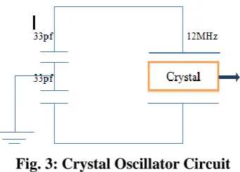
Fig. 3: Crystal Oscillator Circuit
In the above circuit, the crystal oscillator that supplies frequency to trigger the logic gates in microcontroller.
The oscillator to generate the 12MHz frequency in between pin no.18, 19 of microcontroller. The IC 89c51 also
to controlled the relay switch and giving signals to the LCD Display.
3.3. Temperature Sensors (LM 35)
In this system the temperature inside the aluminum cabinet is measured by using LM35 sensor whose output is
given to microcontroller through ADC (0809) to interpret it into Celsius values. The general description
includes the LM35 series are precision integrated-circuit temperature sensors and whose output voltage is
linearly proportional to the Celsius (°C) temperature. The LM35 thus has an advantage over linear temperature
sensors calibrated in ° Kelvin, as the user is not required to subtract a large constant voltage from its output to
obtain convenient Celsius(°C) scaling. The LM35 does not require any external calibration or trimming to
provide typical accuracies of ±1⁄4°C at room temperature and ±3⁄4°C over a full −55 to +150°C temperature
487 |
P a g e
readout or control circuitry especially easy. It can be used with the single power supplies, or with the plus andminus supplies. As it draws only 60 μA from this supply, and it has very low self-heating, less than 0.1°C
(Celsius) in still air.
Fig. 4: LM35DZ Circuit Diagram
3.4. Relay (10a, 24vdc)
The Relay is used to reverse the supply to change the mode i.e. to switch form heating processes to cooling and
vice versa. RW Series Relay covers switching capacity by 10A in spite of miniature size to comply with user’s
wide selection. It is used for the Domestic Appliances, in Office Machines, in Audio Equipment, and
Coffee-Pots, Control units, etc..Hear the relay is used to the purpose of activation of the switch In this project the relay
is used to controlled of the peltier module .If the temperature of panel will increase then the microcontroller fed
the signal to the relay from ADC IC 0809 and relay will turn on and to start the peltier module for cooling
purpose of panel.
Fig. 5: Relay Circuit Diagram
3.5. LCD Display
A liquid crystal display (commonly abbreviated LCD) is a thin, flat display device made up of any number of
488 |
P a g e
Fig. 6: Interfacing LCD with Microcontroller IC 89c51
It is utilized in battery powered electronic devices because it uses small amounts of electric power. In this
system LCD is used to display the currenttemperature values in °C along with indication whether system is in
heating mode or cooling mode. It receives input regarding this information from the micro controller.
IV. WORKING OF THE MODEL
The source for our heater system is renewable energy resource, here PV cells are used. The power from the solar
panel is given to two batteries (12V, 7.25A). From batteries the power is delivered to peltier modules (3 no’s)
connected in parallel each attached to their respective heat sinks. Once the module gets the supply, it starts
functioning (either heating or cooling according to its respective mode). The battery also supplies DC fan +fin
(Heat Sink). Microcontroller receives 5V from the A.C power source i.e. through Step down transformer (230V
to 12V),
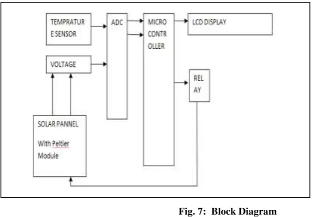
Fig 10 BLOCKS Diagram
Fig. 7: Block Diagram
Which monitors cooling and heating of the system. Temperature sensor-LM35 series are precision
integrated-circuit the temperature sensors, whose output voltage is the linearly proportional to the Centigrade (°C)
temperature is kept inside the System, whose output is given to microcontroller which is programmed to
interpret the voltage into Centigrade temperature values displayed in the LCD Display. In the cooling mode,
489 |
P a g e
the same. For heating process, the supply given to the modules are reversed with the help of relay. Once theterminals are reversed, the heating process starts. During heating, Microcontroller allows power to the module
till the temperature reaches maximum point and it maintains the same. Such that the temperature is maintained
inside the system.
V. COMPARISM RESULTS
TEMPERATURE
VOLTAGE
45°C 40.58 VOLT
35°C 41.99 VOLT
25°C 43.40 VOLT
Fig. 8: Table
VI. SIMULATION RESULT
490 |
P a g e
Fig. 10: From mat lab simulation diagram, we can absorb that when temperature is 35 degree centigradethen voltage increases about 41.99 volt.
.
Fig. 11: From mat lab simulation diagram, we can absorb that when temperature is 25 degree centigrade
then voltage increases about 43.4 volt.
From the above three simulation diagram we conclude that as temperature increases then the voltage decreases
and if the temperature decreases then voltage increases and due voltage increases the overall system efficiency
is also increases.
VII. RESULT
From experimental values it is proved that with the use of thermoelectric cooling system improves the power
491 |
P a g e
Through the combine application of photovoltaic and thermal technologies, the total energy of the overallsystem can be improved by 37%-60%.
VIII. CONCLUSION
In this paper, we conclude that as the use of thermoelectric (TE) cooling system improves the power capacity of
the Photovoltaic by 2%–20% and enhances the power generation efficiency of the photovoltaic by 2.29%–
3.37%. Through the combined application of photovoltaic and thermal technologies and the total energy of the
overall system can be improved by 37%–60%. Also the total efficiency depends on type of module integration
and material type also assumption of the backside is sufficiently cooled such that it is at ambient temperature of
the system.
IX. FUTURE SCOPE AND APPLICATIONS
In future we can build a real time model replacing both air conditioner and room heater in one system, i.e.
Thermo Electric Hot and Cold Room Conditioner. The units of energy production can be developed in the
various regions by using. Peltier(thermoelectric) modules. In these days the society faces the energy crisis but
also harmful effects of the pollution. The thermoelectricity is a “Green Technology” to generate electricity
without any of the harmful effect. The educational institutions, furnace regions, metro cities, industrial areas of
the city, universities and other locations can be selected for the establishment of such energy centers where the
waste heat can be easily available and can be recycled after conversion to the same system
REFERENCES
[1]. Shirin Ahadi, Hamid Reza Hoseini, Rahim Faez, “Using of thermoelectric devices in photovoltaic cells in order to increase efficiency”Iran, 2014.
[2]. Arati Kane, Bharati Vidyapeeth College of Engineering, “Performance Enhancement of Building Integrated Photovoltaic Module using Thermoelectric Cooling”. Delhi, India, vol.3, no.2, 2013.
[3]. Stuart R. Wenham, Martin A. Green, “Applied photovoltaics”, ISBN: 1844074013, Feb 2007.
[4]. Jung-Sik Choi, Jae-Sub KO, and Dong-Hwa Chung.Dept. of Electrical Control Eng., Sunchon
National University, “Development of a Thermoelectric Cooling System for a High Efficiency BIPV Module “Korea ,2012.
[5]. S. C. S. Juca, P.C.M. Carvalho, R. I. S. Pereira, D. Petrov3and U. Hilleringmann Federal Institute of Education, Science and Technology of Ceara, “Design and Implementation of a High Temperature
Control Monitoring Applied to
Micro thermoelectric Generators”, IFCE – Condone Norte Avenue, 10 CEP: 61925-315, Maracanau,
CE (Brazil).
[6]. Amevi Acakpovi, Essel Ben Hagan, “Novel Photovoltaic Module Modeling using Matlab/Simulink”,
International Journal of Computer Applications, Volume-83, 0973-8887.Dec 2013.
[7]. Prasad BN, Saini JS. Optimal thermo hydraulic performance of artificially roughened solar air heaters.
492 |
P a g e
[8]. G.D. Rai, “Non-Conventional Energy Sources,” Khanna Publication, Delhi, Fourth Edition.[9].
Esen, D.O.
; Mech. Dept., Kocaeli Univ., Kocaeli, Turkey ;Balta, E.
;Kaman, A.
“ An experimental investigation of thermoelectric cooling with solar panel”.[10]. Ming-TseKuo, member of IEEE, and Wen-Yi Lo, student member of IEEE in their IEEE transaction
paper, “A Combination of Concentrator Photovoltaic’s and Water Cooling System to Improve Solar
Energy Utilization”.
[11]. B.H. Khan, “Non-Conventional Energy Sources, “Tata McGraw -Hill Publishing Company
Limited, New Delhi, Second Edition.
[12]. Simon Lineykin, Shmuel Ben Yaa, “Modeling and Analysis of Thermoelectric Modules”, IEEE
transaction on industry application, vol. 43, NO. 2, MARCH /APRIL 2007.
[13]. V. Eveloy, P. Rodgers, and S. Bojanampati, “Enhancement of photovoltaic solar module performance for power generation in the Middle East”, in Proc. 28th Annu. IEEE SEMITHERM, 2012, pp. 87–97.
[14]. F.-L. Siaw and K.-K.Chong, “Temperature effects on the performance of dense array concentrator photovoltaic system,” in Proc. IEEE Conf. STUDENT, Oct. 2012, pp. 140–144.
[15]. A. F. Ioffe, Semiconductors Thermo elements and Thermoelectric Cooling. London, U.K.: InfoTech
Limited, 1957.
[16]. S. L. Soo, Direct Energy Conversion. London, U.K.: Prentice-Hall, 1968.