http://www.sciencepublishinggroup.com/j/ijecec doi: 10.11648/j.ijecec.20180401.16
ISSN: 2469-8040 (Print); ISSN: 2469-8059 (Online)
Robust Positive Position Feedback Controller for Voltage
Control of Islanded Microgrid
Dristi Datta
1, 2, *, Md. Rafiqul Islam Sheikh
1, Subrata Kumar Sarkar
3, Sajal Kumar Das
31
Department of Electrical and Electronic Engineering, Rajshahi University of Engineering and Technology, Rajshahi, Bangladesh 2
Department of Electrical and Electronic Engineering, Varendra University, Rajshahi, Bangladesh 3
Department of Mechatronics Engineering, Rajshahi University of Engineering and Technology, Rajshahi, Bangladesh
Email address:
*Corresponding author
To cite this article:
Dristi Datta, Md. Rafiqul Islam Sheikh, Subrata Kumar Sarkar, Sajal Kumar Das. Robust Positive Position Feedback Controller for Voltage Control of Islanded Microgrid. International Journal of Electrical Components and Energy Conversion. Vol. 4, No. 1, 2018, pp. 50-60. doi: 10.11648/j.ijecec.20180401.16
Received: April 19, 2018; Accepted: May 8, 2018; Published: July 4, 2018
Abstract:
This paper presents the design of robust positive position feedback (PPF) controller to control the grid voltage for an islanded microgrid. The microgrid consists of several distributed generators (DG) and local loads which is partially unknown and uncertain. The controller is designed in a way that it shows the robustness against unmodeled loads, dynamic loads and harmonic loads. The dynamics of the plant is identified using differential equations. The design of the controller is presented based on negative imaginary approach. The simulation results presented in the paper show that the controller provides extensive improvement in the voltage control of islanded microgrid under different uncertainties.Keywords:
Islanded Microgrid, Distributed Generator, Robustness, Positive Position Feedback Controller, Negative Imaginary Approach1. Introduction
Microgrid with distributed generation (DG) is considered as an alternative for supplying uninterrupted power to the load. The microgrid provides higher efficiency, energy security, reliability, economics saving and sustainability [1]. The microgrid system is of interest to researchers because of its ability to run independently [5]. Due to lack of fossil fuel the world is more interested to cultivate power from green energy [1-3].
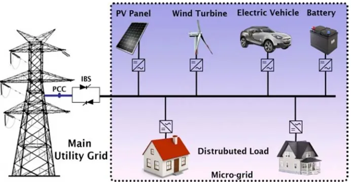
The block diagram of a microgrid system is shown in Figure 1. The microgrid consists of generators such as wind, photovoltaic panel, PCC, energy storage element and controllable loads. The contemplated process of micro grid follows two operation conditions. First one is grid-connected technique and the second one is stand alone technique [2].
During grid connected state the distributed energy resources (DER) backs the main grid whereas rest is connected to it at the PCC. In this contour, frequency and
voltage of the system is being determined by the transmission grid and micro grid can deliberate taking power from main grid. The micro grid can be disjoined from the main grid when a disturbance (fault, power quality and voltage collapse) occurs. Meanwhile, the stand alone microgrid mode is activated [4].
Figure 1. An illustration of islanded microgrid scheme.
The performance of islanded microgrid can be deviated due to number of reasons. For example renewable energy sources are used as prime movers in islanded mode operation of microgrid. The renewable energy sources regulate its real and reactive power from main grid. The performance of renewable energy sources depends on number of reasons such as wind speed, solar strength and others. The variation of these factors results in unsafe operation of power system. The voltage of the microgrid can be oscillated in the transient period due to large number of constant power loads [2, 6]. This results in reduction of stability margin of microgrids voltage. The voltage control of power system is the foremost requirement for microgrid control because of its oscillatory nature. The stability of the microgrid in all modes of operation is the prime engineering requirements.
For islanded operation of microgrid various control strategies have been presented in the technical literature. Hence, for the control of voltage and frequency of an islanded microgrid droop control method is well known technique [5, 7, 8]. In this method parallel inverters are used which enable inverting the supply voltage. It provides balancing power for both islanded and grid this modes, when the load dynamics is excluded from the control loop. Real and reactive power is supplied by the control strategy with inverting voltage and frequency deviation having the load dynamics with control loop. The power sharing accuracy is limited in this method due to these alleviations.
Distributed control [9] and decentralized control [10] techniques have been proposed in microgrid systems to compensate voltage and frequency deviation. A number of parameters are measured by these control techniques from a remote sensing block and sent back to the controlled with the help of low bandwidth communication system. Slow controls loops and low bandwidth are the major drawbacks of these control technique.
In order to achieve higher bandwidth and steady state performance for the voltage and frequency control in power system Hierarchical control strategy [11] is widely used. Three levels namely primary, secondary and tertiary level can
be obtained by dividing this control technique. Different types of controllers have been used in each of these levels. Specific objectives and comprising separates methods of controlling have been performed by each level. On the other hand, it cannot regulates shearing power of microgrid when one level of hierarchical control techniques have fallen shut down due to uncertainty.
In order to regulate the voltage or active power and frequency or reactive power in microgrid system classical Proportional Integral Derivative (PID) and Proportional Integral (PI) controllers [12] are used. Power balance is maintained in microgrid systems by widely using both controllers. Although simplicity and ease of implementation are the advantages of these controllers but low band width and poor robustness are the major limitations of PID controller against the change of load dynamics.
Robust H-infinity controller [13] has been proposed with unmolded load formulation for microgrid. With presence of variations of plant dynamics, it provides robust performance. In the designing of H-infinity controller, the order of the system plays vital role. Advanced digital signal processing system may be required when high order system dictates high order of controller.
The linear quadratic regulator (LQR) can be used to control the voltage of microgrid and for better voltage regulation and simultaneous load sharing [14]. LQR controller is based on linearization technique which is controlled by means of a droop control method without using communication link on which the system depends. The performance of LQR controller depends on a plant transfer function. If the plant transfer function is constant then the performance of LQR controller is very high but if the transfer function varies due to different types of uncertainty then its performance is not satisfied. So the controller suffers from the lack of robustness against the changes of plants dynamics.
type of controller is designed to regulate the line voltage by providing reactive power compensation and balancing the power in microgrid. The feedback linearization technique is algebraically transforms a nonlinear system into a fully linearization. It can stabilize the whole system in large scale region to the presence of large harmonics. But microgrid system becomes more popular as the interconnection of generators is very close to each other. Hence the individual performance is affected by the progressive performance of other. In this case it is required to investigate another controller which can reduce the limitation of feedback linearization controller.
To minimize these problems Proportional Integral resonant controllers (PI-REs) is investigated and it gives better performance in microgrid system [17]. This is also named as damping controllers. This is a low pass controller with low gain margin in high resonance frequencies. Another type of damping controllers named proportional resonant controller (PR) is considered in microgrid system for voltage control [18]. But it also suffers from lower gain and phase margin in high frequencies.
This paper presents the design of a novel controller called positive position feedback (PPF) controller for microgrid system to control the voltage of the grid. The PPF control is a robust control technique that is used to control the resonance of smart actuators. The design of PPF controller is of interest because of low order transfer function, ease of implementation and robustness against the perturbation of plant dynamics. It is a low pass controller which ensures its ability to reduce high frequency sensor noises as well [10].
The design of the controller is presented based on a negative imaginary (NI) method [19-20]. A single input single output transfer function is said to be NI if the phase of the system lies between [-1800, 0]. The positive feedback interconnection of two NI systems is stable if one of the systems is strictly NI and the product of DC loop gain of the systems is less than one.
The rest of the paper is organized as follows. Section 2 presents the modelling of the islanded microgrid, Section 3 shows the control design. Section 4 describes the performance evaluation by showing simulation results of the proposed model. The paper is concluded in Section 5.
2. Modelling of Islanded Microgrid
2.1. Microgrid Configuration
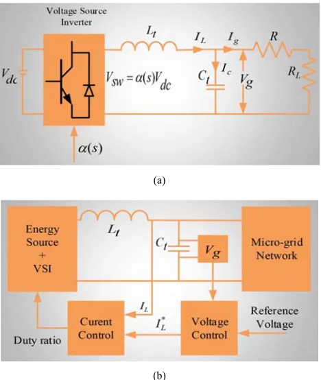
An islanded microgrid consists of voltage source inverter (VSI) which couples between AC and DC region shown in Figure 2 (a). Here VSI interfaces between primary energy sources (DC side) with microgrid (AC side) and L-C filter is used to attenuate the switching ripple. As the microgrid may run single or multiple power sources, it is controlled by two control loops. Figure 2 (b) shows this. Here the outer controller determines the set value Vg of the inner grid voltage control loop.
(a)
(b)
Figure 2. (a) Single phase single energy source microgrid system, (b) Closed-loop control strategy in single phase MG with VSI (Voltage Source Inverter).
2.2. Voltage Control
In this study, the expected voltage Vg is tracked for each VSI by the voltage control loop method. The duty ratio, δ is determined by the controller of VSI switches with δ Є [-1, 1] by using the method of pulse width modulation [PWM]. High bandwidth is needed for this control loop to achieve perfect voltage tracing. Different control strategies can be taken for this purpose.
The VSI control usually obtained in in the rotating dq-reference frame in three phase configurations. In this case, synchronous frame results more complicated control system as it requires transforming ac quantities to dc quantities. This may introduce error if the synchronous frame identification is not accurate.
As shown in Figure 2 (a) microgrid extracts power from a power source Vdc. From this figure it is seen that the inductor current iL is divided into filter capacitor current iC and grid current ig (iL = iC + ig).
The controller’s design stand on:
( ) ( ) di
L
L Vsw t Vg t
dt = − (1)
With Vsw the switching voltage over a pulse width modulation state is-
Vsw V dc
δ
= (2)
( ) ( ) dVg t
C i tc
dt = (3)
The derived state-space model is-
; dx
Ax Bu y Cx Du
dt = + = + (4)
Here the state vector x and the input vector u of the microgrid system. The state disturbances d are also considered which is next to the state vector and input vector. These disturbances carry grid current because the microgrid structure is unknown for controlling tuning and changeable during the operation when loads or generator turn on and off.
L g i x V =
;u=
[ ]
Vsw ;^
g
d = =d i (5)
L g i x V =
;u=
[ ]
Vsw ;^
g
d = =d i (6)
The state space can be presented using the following equation-
1
0 1
0
[ ] 1 [ ]
1 0 0 L L SW g g g i i
d L V i
L V V dt C C − = + + − (7)
So that, the system-state and system output is-
[ ] [ g] [0 1] L g i y V V = =
(8)
3. Controller Design
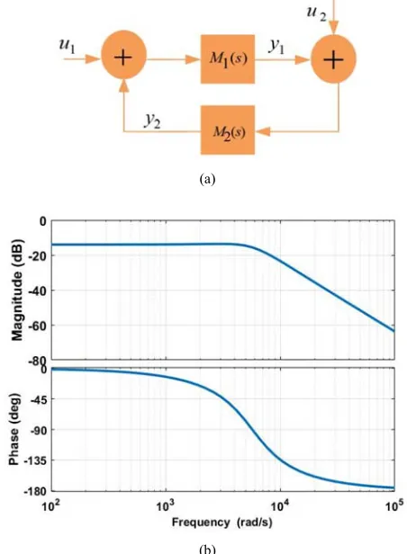
This section presents a brief discussion of the design of the PPF controllers to control the voltage of the islanded microgrid. The structure of the closed-loop system is shown in Figure 3 (a), where M1(s) and M2(s) are the plant transfer function and the PPF controller transfer function, respectively, u1 is the reference signal and y1 is the output from the system. Figure 3 (b) shows the bode diagram of the controller.
The general form of the transfer function PPF controller is as follows:
2
2( ) 2 2
2 n v
n n
M s K
s s
ω
ω ξ ω
=
+ +
Where kv >0 is the gain of the controller, ξ >0 and ωn >0
are the damping constant and the frequency at which resonant mode needs to be damped.
In the design process, choosing the right value of ωn is
important. It is required that ωn is chosen to be equal or
nearly equal to the first resonance frequency of the system.
The amount of damping of the resonant mode depends on ξ and Kv. Choosing a low value of ξ would introduce a notch
and undesirable phase shift in the closed loop. For a high value of ξ, there is hardly any damping. The value of Kvhas
an important effect on damping and stability. A low value of Kvleads to a low level of damping of the resonant mode and
a high value of Kvcan make the closed-loop system unstable.
In the design we select Kv =0.2, ωn =5700, ξ=0.6.
The stability of the closed loop system shown in Figure 4 can be established using the NI approach. From the Bode diagram of the system and the controller it can be seen that both the systems are NI and one of them is strictly NI as shown in Figure 4(a) and Figure 4(b).
Figure 4(a) presents the open loop and close loop bode a diagram. From this figure it is seen that the resonance pick has reached almost 150dB in open-loop where as it is very smooth and near about zero dB for closed-loop.
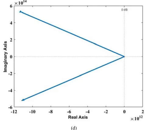
The loop gain of the interconnection at zero frequency is less than zero. The nyquist and rootlocus loop gain for niminal plant is presented in Figure 4(c) and Figure 4(d). From the both of it is observed that the closed-loop system is stable. For the simulation DC bus voltage is considered 400V and the L-C filter parameters are C = 15F and L = 2mH. The line resistance is considered RL = 3 ohm and the load resistance R = 20 ohm.
(a)
(b)
(a)
(b)
(c)
(d)
Figure 4. Closed-loop responses of using positive feedback controller (a) Bode diagram, (b) Bode diagram for different capacitor value, (c) Root locus plot of loop gain using nominal plant, (d) Nyquist plot of loop gain using nominal plant.
4. Performance Evaluation
The proposed controller design in the previous section has been simulated. The modeling of different uncertainty and its corresponding performance of proposed controller is presented in Figure 5 and Figure 6. The simulation results reported from Figure 7 to Figure 9. The proposed controller shows the unique characteristic of robustness with the parameter variation. In the controller design capacitor value is chosen 15µF but in practice the real value of capacitor is about 30µF and may change. Comparative curve of Bode plot is studied. However, when the value of capacitor is chosen 50µF the vary less variation is noted which is shown in Figure 4(b). All cases the controller remains stable.
4.1. Performance Against Dynamic Load
Microgrid is considered as a small power system where the dynamic loads are important as these types of load has a considerable effect on power system stability.
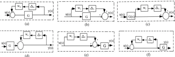
Figure 5. (a) Additive uncertainty, (b) Multiplicative output uncertainty, (c) Inverse multiplicative output uncertainty, (d) Multiplicative input uncertainty, (e) Inverse additive uncertainty, (f) Inverse multiplicative input uncertainty.
4.2. Performance Against Harmonic Load
In a microgrid, several non-linear loads are connected in parallel with each other which produces harmonics in the power system. The two types of harmonics i.e. voltage harmonics and current harmonics produce excessive heating of loads as well as conductors which reduce the performance and durability of the loads. According to the nature of loads the waveform of current is dependent but sometimes it may not be sinusoidal as the harmonics is presented in the wave.
As a result, the quality of voltage is collapsed. This result increased current magnitude of 3rd order harmonics. To generate these types of harmonics, a current source of amplitude 7A, frequency of 150Hz and a resistor of 30 ohm are connected in series.
4.3. Performance Against Unknown Load
It is very important to analyze the robustness against the unknown loads as the performance of microgrid is affected severely by the uncertain loads. The parameters of unknown load are R =62.86, inductor L= 223.8 mH connected in series with 0.35 ohm and resistor 228 ohm parallel connected. After t=0.35s the parameters is changed and associated with other new parameters values that are unknown. So the performance of the controller may be affected. But this controller shows the good performance over the unknown load for tracking microgrid reference voltage despite the uncertainties in the unknown load resistance.
4.4. Performance against Non-linear Load
In a power system major portion of loads are non-linear loads. In this analysis, a two phase four pulse diode bridge rectifier is considered as a non-linear load. The performance of the controller over the non-linear loads proves the robustness and the stability of the controller.
4.5. Performance against Asynchronous Machine Load
In this section the performance of controller over the asynchronous machine is analysed. For that an induction motor with dq stator reference frame having a zero steady-state condition with capacitor start and capacitor start run condition is considered which is connected in parallel with the microgrid
system. As the variation of active and reactive power of the dynamic load the power of the system is also affected.
All the variation of voltage and current under the different load condition is presented in Figure 6 to Figure 8. The examination of both of figure verifies that the proposed controller shows the reliable and robust performance in all cases. From Figure 9, it is mentioned that the current is also controlled in fault situations using the proposed controller. This performance of proposed controller implies the high performance inclusion of different criteria.
(a)
(c)
(d)
Figure 6. Comparison of open loop uncertainty (-), open- (-) and closed-loop (-) Bode diagram (a) for Figure 5(a), (b) for Figure 5(b) and 5 (c), (c) for Figure 5(d), (d) for Figure 5 (e) and 5 (f).
(a)
(b)
(c)
(e)
(f)
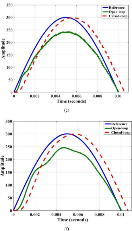
Figure 7. Comparison of open-loop, closed-loop and reference grid voltage using positive position feedback controller (a) consumer load, (b) dynamic load, (c) harmonic load, (d) asynchronous machine load, (e) unknown load model and (f) Nonlinear load.
(a)
(b)
(c)
(e)
(f)
Figure 8. Comparison of open-loop, closed-loop and reference grid voltage using positive position feedback controller (a) consumer load in zoom view, (b) dynamic load in zoom view, (c) harmonic load in zoom view, (d) asynchronous machine load in zoom view, (e) unknown load model in zoom view and (f) Nonlinear load in zoom view.
(a)
(b)
(c)
(e)
(f)
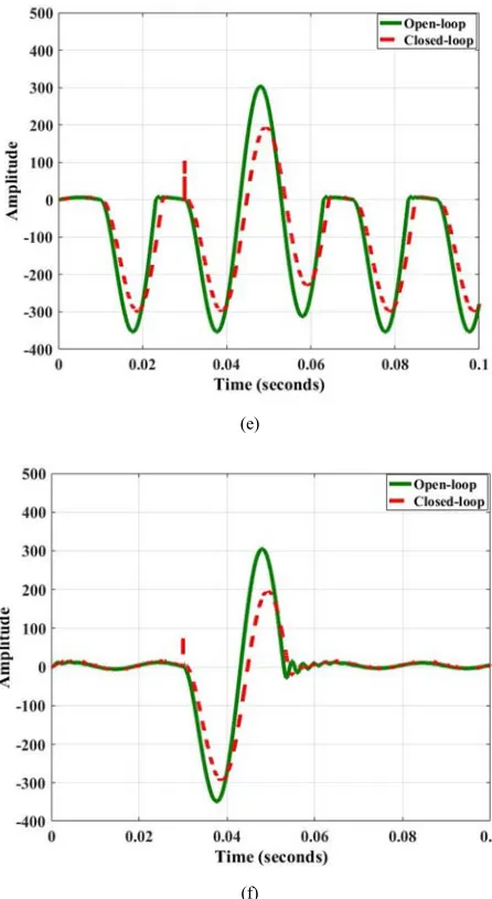
Figure 9. Comparison of open and closed loop fault current tracking using positive position feedback controller (a) Consumer load, (b) Dynamic load, (c) Harmonic load, (d) Asynchronous machine load, (e) Unknown model load and (f) Nonlinear load.
5. Conclusion
The design of a robust positive position feedback controller for microgrid voltage control is presented in this paper. The proposed controller provides 150 dB damping of the resonant mode. Different types of uncertainty with different types of load are also analyzed for the proposed controller. In every case the controller remains stable against the changes in plant dynamics and provides satisfactory performance. This work can be extended for multi-input multi-output cases.
References
[1] A. M. Bouzid, J. M. Guerrero, A. Cheriti, M. Bouhamida, P. Sicard, and M. Benghanem., 2015 “A survey on Control of Electric Power Distributed Generation Systems for Microgrid Applications,” Renewable and Sustainable Energy Reviews, vol. 44, pp. 751–766.
[2] A. Llaria, O. Curea, J. Jimenez, and H. Camblong., 2011 “Survey on Micro- ´grids: Unplanned Islanding and Related Inverter Control Techniques,” Renewable energy, vol. 36, no. 8, pp. 2052–206.
[3] M. Mahmoud, S. A. Hussain, and M. Abido., 2014 “Modeling and Control of Microgrid: An Overview,” Journal of the Franklin Institute, vol. 351, no. 5, pp. 2822–2859.
[4] B. Kroposki, R. Lasseter, T. Ise, S. Morozumi, S. Papatlianassiou, and N. Hatziargyriou., 2008 “Making Microgrids Work,” IEEE power and energy magazine, vol. 6, no. 3.
[5] G. Carpinelli, F. Mottola, D. Proto, and P. Varilone., 2017 “Minimizing Unbalances in Low-Voltage Microgrids: Optimal Scheduling of Distributed Resources,” Applied Energy, vol. 191, pp. 170–182.
[6] M. Hamzeh, M. Ghafouri, H. Karimi, K. Sheshyekani, and J. M. Guerrero., 2016 “Power Oscillations Damping in DC Microgrids,” IEEE Transactions on Energy Conversion, vol. 31, no. 3, pp. 970–980.
[7] Q. Salem and J. Xie., 2016 “Transition from Grid-Connected to Islanded Drooped Microgrid Based on Islanding Detection Scheme,” International Journal of Power and Energy Systems, vol. 36, no. 3.
[8] H. Han, Y. Liu, Y. Sun, M. Su, and J. M. Guerrero., 2015 “An Improved Droop Control Strategy for Reactive Power Sharing in Islanded Microgrid,” IEEE Transactions on Power Electronics, vol. 30, no. 6, pp. 3133–3141.
[9] S. Bolognani and S. Zampieri., 2013“A Distributed Control Strategy for Reactive Power Compensation in Smart Microgrids,” IEEE Transactions on Automatic Control, vol. 58, no. 11, pp. 2818–2833.
[10] M. S. Golsorkhi and D. D.-C. Lu, 2016 “A Decentralized Control Method for Islanded Microgrids under Unbalanced Conditions,” IEEE Transactions on Power Delivery, vol. 31, no. 3, pp. 1112–1121.
[11] Y. A.-R. I. Mohamed and A. A. Radwan., 2011 “Hierarchical Control System for Robust Microgrid Operation and Seamless Mode Transfer in Active Distribution Systems,” IEEE Transactions on Smart Grid, vol. 2, no. 2, pp. 352–362. [12] X. Li, Y.-J. Song and S.-B. Han, 2008 “Frequency Control in
Microgrid Power System Combined with Electrolyzer System and Fuzzy PI Controller,” Journal of Power Sources, vol. 180, no. 1, pp. 468–475.
[13] T. Hornik and Q.-C. Zhong, 2013 “Parallel PI Voltage-H Current Controller for the Neutral Point of a Three-Phase Inverter,” IEEE Transactions on Industrial Electronics, vol. 60, no. 4, pp. 1335–1343.
[14] S. Alepuz, J. Salaet, A. Gilabert, J. Bordonau, and J. Peracaula, “Control of three-level VSIs with a LQR-based Gain-Scheduling Technique Applied to DC-link Neutral Voltage and Power Regulation,” in IECON 02 [Industrial Electronics Society, IEEE 2002 28th Annual Conference of the], vol. 2. IEEE, 2002, pp. 914–919.
[15] M. A. Mahmud, H. Pota, and M. Hossain, 2013 “Nonlinear DSTATCOM Controller Design for Distribution Network with Distributed Generation to Enhance Voltage Stability,”
[16] M. Mahmud, H. Pota, and M. Hossain, 2012 “Full-order Nonlinear Observer based Excitation Controller Design for Interconnected Power Systems via Exact Linearization Approach,” International Journal of Electrical Power & Energy Systems, vol. 41, no. 1, pp. 54–62.
[17] M. Liserre, R. Teodorescu, and F. Blaabjerg, 2006 “Multiple Harmonics Control for three-phase Grid Converter Systems with the Use of PIRES Current Controller in a Rotating Rrame,” IEEE Transactions on power electronics, vol. 21, no. 3, pp. 836–841.
[18] G. Shen, X. Zhu, J. Zhang, and D. Xu, 2010 “A new Feedback Method for PR Current Control of LCL-filter-based
Grid-Connected Inverter,” IEEE Transactions on Industrial Electronics, vol. 57, no. 6, pp. 2033–2041.
[19] S. K. Das, H. R. Pota, and I. R. Petersen, 2014 “Resonant Controller Design for a Piezoelectric Tube Scanner: A Mixed Negative-Imaginary and Small-Gain Approach,” IEEE Transactions on Control Systems Technology, vol. 22, no. 5, pp. 1899–1906.