IJSRSET1848142 | Received : 05 June 2018 | Accepted : 15 June 2018 | May-June-2018 [ 4 (8) : 475-481]
Themed Section : Engineering and Technology
475
Comparative Study of RC Framed Structure and Tubular
Structures
Dattaprasad Patil1, Prachi Sohoni2
1M.Tech Structural Engineering, Walchand College of Engineering, Sangli, Maharashtra, India
2Assistant Professor, Applied Mechanics Department, Walchand College of Engineering, Sangli, Maharashtra,
India
ABSTRACT
In developing countries like India some cities are overcrowded with population and count is increasing annually at the rate of 1.2% as per year 2016 data, therefore the demand for high rise buildings is increased. As height of building increases, lateral loads such as wind and earthquake must be considered along with gravity loads. As compared to vertical loading, lateral load effect on a building increases exponentially with increase in its height. Engineers have developed several new framing schemes for tall buildings in order to minimize the effect of lateral loads. Present work aims to study and compare seismic response of structures subjected to non-linear dynamic analysis. For this study framed structure, framed tube structure and tube-in-tube structure are considered. Results are compared in terms of structural parameters like maximum lateral displacement, maximum storey drift, base shear, and shear lag. ETABS 2016, the structural software for building analysis and design is used for analysis.
Keywords: Framed structure, Framed tube structure, Tube-in-tube structure, Non-linear dynamic analysis, ETABS.
I.
INTRODUCTIONConstruction of high rise buildings is result of increased population. Due to industrialisation large population migrates towards cities. In metro cities of India there is space limit for horizontal growth so solution is vertical development. In structures built at the beginning of 20th century, structural members
were assumed to carry primarily the gravity loads. Now a days due to advancements in structural designs/systems and high-strength materials, building weight is greatly reduced and slenderness has increased, which has demanded the consideration of lateral loads such as wind and earthquake in the design process. Lateral forces resulting from wind and
seismic activities are now dominant in design considerations. Lateral displacement of such buildings must be strictly controlled, not only for occupants comfort and safety but also to control secondary structural effects.
safety of the structure which in turn ensures no harm to the society. More the height of building, more it is necessary to identify the proper structural system that can be used for the lateral resistance of high rise buildings. Currently, there are many structural systems such as rigid frame, braced frame and shear-wall frame, frame-tube, braced-tube, bundled-tube, and outrigger systems that can be used to improve the lateral resistance in tall buildings.
II.
TYPES OF STRUCTURAL SYSTEMSFrom the structural engineer’s point of view, the determination of the structural form of a high rise building would involve selection and arrangement of the major structural elements to resist the various combinations of gravity and horizontal loading more efficiently. The taller and more slender a building, the more important it is to choose an appropriate structural form. Following is the classification suitable for reinforced concrete buildings, steel buildings and composite buildings.
Rigid frame system
Braced frame and shear-wall frame system Frame-tube system
Braced-tube system Tube-in-tube system Bundled-tube system Outrigger system
A. Rigid Frame System
This system consists of columns and beams joined by moment resistant connections. Lateral stiffness of a rigid frame depends on the bending stiffness of the columns and beams. This is ideally suitable for reinforced concrete buildings because of the inherent rigidity of reinforced concrete joints. It can also be used for steel frame buildings, but moment-resistant connections in steel tend to be costly. While rigid frame is economical up to height of about 25 to 30 stories, above that height flexibility of the frame will
be relatively high and it will require large members, in order to control the drift and displacements.
B. Framed Tube System
Framed tube system consists of closely spaced columns joined by deep beams at periphery and acts as tube, so that the whole building works as a huge vertical cantilever to resist overturning moments. The lateral load is resisted by this tube around the perimeter of the building and the gravity load is shared between the tube and interior columns or walls. Besides its structural efficiency, framed-tube buildings leave interior floor plan free of heavy columns, enhancing net usable floor area. Depending on the height and dimensions of the building, exterior column spacing should be kept between 2 m to 4 m center to center.
C. Tube-in-Tube System
Tube-in-tube structure is advancement in framed tube structure and consists of an inner tube in addition to an outer frame tube. The inner tube which may consists of braced frames or shear wall enclosing service core or closely spaced columns connected by beams, similar to outer tube. Outer and inner tubes are interconnected through floors and acts jointly in resisting both gravity and lateral loading. The outer framed tube and the inner core interact horizontally as the shear and flexural components of a wall-frame structure, with the benefit of increased lateral stiffness.
III.
NON-LINEAR TIME HISTORY ANALYSISadding higher order terms in the equation. This method consists of performing a time-history analysis in the non-linear domain. The seismic action is directly applied, by means of accelerogram, at the base of the structure.
IV.
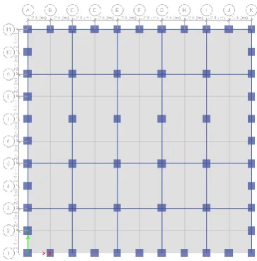
MODLING OF BUILDINGFor this study 30 storied framed structure, framed tube structure and tube-in-tube structure are considered with plan dimension 24m x 24m. The structures are considered to be located in zone IV and designed according to IS 456:2000. The structures are considered to be fixed at the base. The structures are modeled using software ETABS 2016. Models are studied for comparing maximum lateral displacement, maximum story drift, base shear and shear lag.
The data used for modelling of buildings is given in Table I and Table II
Figure 1: Plan of Framed Structure
Figure 2: Plan of Framed Tube Structure
Figure 3: Plan of Tube-in-tube Structure
TABLE I
COMMON DETAILS OF BUILDINGS No. of storey 30 Each storey height 3 m
Thickness of slab 125 mm Grade of concrete M 40
Grade of steel Fe 500 Importance factor 1.5 Response reduction
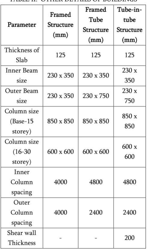
TABLE II. OTHER DETAILS OF BUILDINGS Parameter Framed Structure (mm) Framed Tube Structure (mm) Tube-in-tube Structure (mm) Thickness of
Slab 125 125 125 Inner Beam
size 230 x 350 230 x 350
230 x 350 Outer Beam
size 230 x 350 230 x 750
230 x 750 Column size
(Base-15 storey)
850 x 850 850 x 850 850 x 850
Column size (16-30 storey)
600 x 600 600 x 600 600 x 600
Inner Column
spacing
4000 4800 4800
Outer Column
spacing
4000 2400 2400
Shear wall
Thickness - - 200
The loads considered for the modelling of buildings are given in Table III
TABLE III. LOADING DETAILS
Sr. no. Load type Value (kN/m2)
1 Live load 5 2 Floor finish load 1
A. Time history data
Various time histories were applied on the buildings and the response was checked. Among applied ones, time histories which gave maximum response were selected and listed below:
El Centro
Gazli USSAR
Imperial valley
Santa Monica, California
Sylmar-country hospital
V.
RESULTS AND DISCUSSIONThe structures are analyzed using software ETABS 2016 for five different time history data. Results are compared for maximum lateral displacement, maximum story drift, base shear and axial force distribution in column.
A. Results for Lateral Displacement:
Table IV shows displacement of buildings for different time history.
TABLE IV. COMPARISON OF DISPLACEMENT OF BUILDINGS
Time History Displacement (mm) FS FTS TTS
El Centro 180.85 60.23 40.75
Gazli USSR 178.65 57.73 47.81
Imperial
Valley 270.77 76.96 58.44
Santa Monica 296.85 56.45 52.5
Sylmar
Country 220.36 52.37 47.37
Figure 1: Max. Lateral Displacement of Buildings
From table IV and figure 4 it is observed that FS has large displacements for various time histories. FTS has 67-81 % less displacement compared to FS, TTS has 77-87 % less displacement compared to FS and 7-32 % less displacement compared to FTS for various time histories.
B. Results for Storey Drift:
Table V shows storey drift of buildings for different time history.
TABLE V. COMPARISON OF STOREY DRIFT OF BUILDINGS
Time History Storey Drift (mm) FS FTS TTS
El Centro 9.20 2.69 1.77
Gazli USSR 9.27 3.61 2.59
Imperial
Valley 12.23 3.64 2.55
Santa Monica 12.46 3.23 2.09
Sylmar
Country 9.53 2.43 2.02
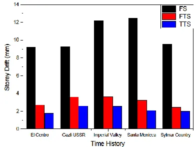
Figure 5 shows the storey drift of the buildings for various time histories
Figure 2: Storey Drift of Buildings
From table V and figure 5 it is observed that FS has large drift for different time histories. FTS has 61-74 % less drift compared to FS, TTS has 72-83 % less drift compared to FS and 17-35 % less drift compared to FTS for various time histories.
C. Results for Base shear:
TABLE VI. COMPARISON OF BASE SHEAR OF BUILDINGS
FS FTS TTS Base Shear (kN) 4234.18 4459.87 4538.16
Figure 6 shows the base shear variation of buildings
Figure 6: Base Shear variation of Buildings
D. Results for Axial Force (Shear Lag):
Though FTS is very good in resisting lateral loads it has considerable degree of shear lag. Shear lag is phenomenon where axial force distribution in periphery columns is uneven.
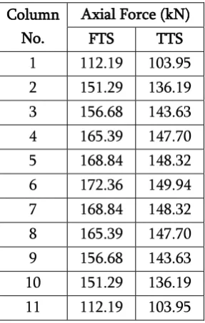
TABLE VII
COMPARISON OF AXIAL FORCE IN PERIPHERY COLUMNS OF BUILDINGS
Column No.
Axial Force (kN) FTS TTS 1 112.19 103.95 2 151.29 136.19 3 156.68 143.63 4 165.39 147.70 5 168.84 148.32 6 172.36 149.94 7 168.84 148.32 8 165.39 147.70 9 156.68 143.63 10 151.29 136.19 11 112.19 103.95
Figure 7 shows the axial force variation for periphery columns of buildings.
Figure 7: Axial Force variation of periphery columns of Buildings
From table VII and figure 7 it is observed that, FTS has uneven distribution of axial forces, so it is affected by shear lag. TTS has slightly even distribution of axial forces in columns. So shear lag is reduced in TTS due to introduction of inner tube (shear wall).
VI.
CONCLUSIONThe analysis of 30 storied framed structure, framed tube structure and tube-in-tube structure for five different time history is carried out. Results for lateral displacement, storey drift, base shear and axial force in columns shows that, tube-in-tube structure is best suitable for resisting lateral loads caused due to earthquake, when compared to framed structure and framed tube structure.
VII.
REFERENCES[1] Han, R. P. S. (1989). “Analysis of framed tube structures of arbitrary sections.” Applied
Mathematical Modelling, 13.
[2] Haji-Kazemi, H., and Company, M. (2002). “Exact method of analysis of shear lag in framed tube structures.” The Structural Design of Tall
Buildings, 11, 375–388.
[3] Kobielak, S., Tatko R., Piekarz R. (2010). “Method for approximate analysis of cracking effect on lateral stiffness of reinforced concrete framed-tube structures.” Archives Of Civil And
Mechanical Engineering, 10.
[4] Lee, K. K., Loo, Y. C., Guan H. (2001). “Simple analysis of framed-tube structures with multiple internal tubes.” Journal of Structural
Engineering, 127(4).
[5] Mahjoub, R., Rahgozar, R., Saffari, H. (2011). “Simple method for analysis of tube frame by consideration of negative shear lag.” Australian
Journal of Basic and Applied Sciences, 5(3),
309-316.
tube.” Structural Engineering and Mechanics, 49 (3), 297-309.
[7] Memari, A. M., Motlagh, A., Y., Scanlon, A. (2000), “Seismic evaluation of an existing reinforced concrete framed tube building based on inelastic dynamic analysis.” Engineering
Structures, 22, 621–637.
[8] Rahgozar, R., Ahmadi, A., R., Sharifi, Y. (2010). “A simple mathematical model for approximate analysis of tall buildings.” Applied
Mathematical Modeling, 34, 2437–2451.
[9] Rahgozar, R., and Sharifi, Y. (2009). “An approximate analysis of combined system of framed tube, shear core and belt truss in high-rise buildings.” The Structural Design of Tall