Active and Reactive Power Control of DFIG for
Wind Energy Conversion Using Back to Back
Converters (PWM Technique)
Mojtaba Shokouhi Nia, Mostafa Bahmani*
Department of Electrical Engineering, Islamic Azad University, Damghan Branch, Damghan, Iran
*Corresponding Author email : [email protected]
Abstract: Wind energy is utilizing the air flow through wind turbines to generate the electrical power and energy. In this paper, we proposed a new method for controlling the stator active or reactive power ripple components under unbalanced grid voltage for wind power generation using doubly-fed induction generators (DFIG) by employing the PWM controller. Direct control strategy is utilized for the stator active and reactive power by selecting appropriate voltage vectors on the rotor side. Simulation results on a 9 MW DFIG system are provided to illustrate the proposed control strategy effectiveness during variations of reactive and active power, converter dc link voltage and rotor speed. The system is simulated by using MATLAB software and the results showed that the achieved strategy make a good control performances of the system.
Keywords:Active and Reactive power, Doubly Fed Induction Generator (DFIG), Wind Turbine, PWM control.
INTRODUCTION
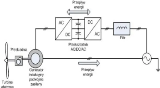
One of the standards for drive option for high-power applications including a limited speed range is doubly fed induction machine connected to an AC/DC/AC converter in the rotor circuit. Power converter in here has a duty to handle the rotor power. Vector-control methods are one of the popular strategies for the independent control of rotor excitation current and torque (Leonhard W, 2001). Jones and Jones have proofed that we can utilize a vector-control strategy for decoupled controlling of the reactive and active power drawn from the supply (Jones, s.r., and Jones, k, 1993). DFIG systems can be employed as a current-fed (naturally commutated) DC-Link converter (Smith, G.A et al, 1981; Uctug, M.Y. et al., 1994) or as a cyclo-converter (Machmoum, M., et al. 1992) in the rotor circuit. T. Brekken and N. Mohan (2003) proposed a DFIG control strategy to reduce torque ripple for unbalanced grid voltage, by not considering the active and reactive power ripple components. H. S. Song and K. Nam (1999) presented a sensational dual current control technique by employing the positive and the negative sequence current components in ac/dc PWM converter systems. Schematic diagram of a DFIG device is shown in the Figure in below.
Figure 1. Schematic diagram of DFIG-based wind generation systems.
DFIG Model
amount is suitable for the generator to use the magnetic fields to convert the rotational energy into electrical energy. The current-voltage equations of the stator and rotor in a d-q synchronously rotating reference frame can be presented as below:
qs
qs s qs ds
d
v
R i
dt
(1)qs ds ds s ds
dt
d
i
R
v
(2)dr r qr qr r qr
dt
d
i
R
v
(
)
(3) qr r dr dr r dr
dt
d
i
R
v
(
)
(4)Where is the synchronous angular frequency, ris the slip angular frequency and Rr and Rs are equivalent
resistances of stator and rotor windings, respectively. The flux equations can be illustrates as below:
qr m qs s
qs
L
i
L
i
(5)dr m ds s
ds
L
i
L
i
(6)qs m qr r
qr
L
i
L
i
(7)ds m dr r
qr
L
i
L
i
(8)m ls
s
L
L
L
(9)m lr
r
L
L
L
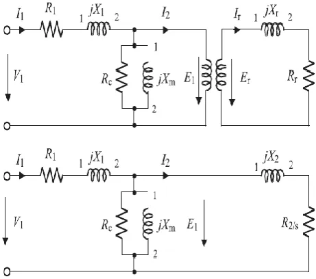
(10)Where L L Lr, s, mare mutual and self inductances of stator and rotor windings, respectively (L. Xu and Y. Wang, 2007).
Figure 2. Equivalent circuit of the popular induction machine
Active and Reactive Power Control System using PWM
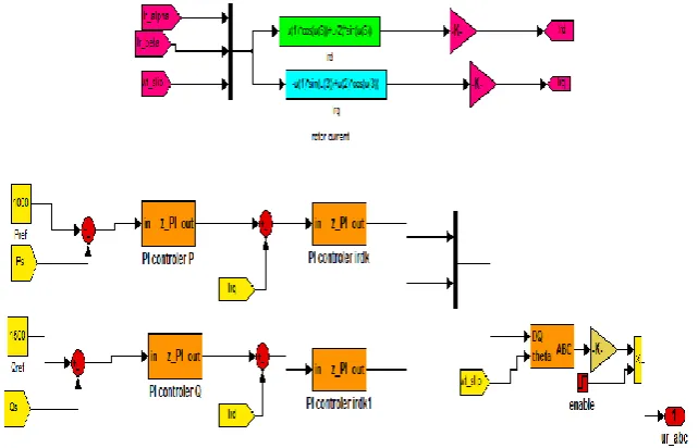
In this method, the voltages and the currents of the 3-phase stator are first converted into the d-q coordinate. After that, the active and the reactive powers are then evaluated. The active and the reactive powers equations are given in below:
( )
(11)
Figure 3. Stator active and reactive powers
By using these achieved active and reactive powers and DC voltage link, the control signal will be produced. For this purpose, a PI controller can be used to achieve the basis value of the Irq and Ird which is
achieved by the error of the real and the desired values of the active and reactive powers. Afterwards, a signal by using the Irq and Ird will be produced in the abc coordinate.
Figure 4. control loop for the DFIG
The reference signal will be made by using the achieved control signal and the DC voltage link where it's difference by a triangle wave will be made the considered PWM for the converter control signal. This means that if the triangular wave's value gets bigger than the reference signal, the output will be 1, otherwise it will be 0.
Figure 6. PWM control wave
Simulation Results
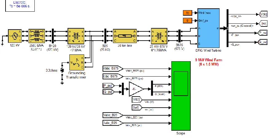
For analyzing the proposed control strategy, computer simulations are performed using Matlab simulink. The analyzed system is selected from the (S. Morimoto et al., 2005). The DFIG used for simulation is rated at 9MW, generator output voltage is constant at 575v, the inductance and the resistances of the stator winding are 0.18pu and 0.023 pu respectively. The inductance and the resistance of the rotor winding are 0.16pu and 0.016pu respectively and the numbers of the magnetic poles are 6 and the inertia moment of the rotor is 0.685.The simulated system is shown in the figure below:
Figure 7. Active and reactive power control system of DFIG by using PWM method
we assumed that a voltage downfall is happened in the network in the time interval 0.03-0.13. Here, the reactive power reference is considered zero and constant wind speed is equal to 10m/sec
The simulation results are given in the below:
Figure 8. the voltage of the network
The injected currents to the network are shown in the figure below. As it can be seen, after error correction, the current is back to the normal situation.
0 0.05 0.1 0.15 0.2 0.25 0.3 0.35 0.4 0.45 0.5 -2
-1 0 1 2
time (sec)
Vg
Figure 9. stator current of the network side
The next figure shows the voltage variations of the DC link.
Figure 10. DC link voltage variations.
Active and reactive power variations during the error are shown in the fig.11. As it can be seen, the system controller causes the active power injection during the error.
Figure 11. active and reactive power variations of the stator output.
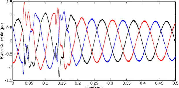
In the fig. 12, the rotor winding current is shown during the error.
Figure 12. 3-phase currents of the rotor winding
0 0.05 0.1 0.15 0.2 0.25 0.3 0.35 0.4 0.45 0.5 -2
-1.5 -1 -0.5 0 0.5 1 1.5
time (sec)
Grid
C
urre
nt
(A)
0 0.05 0.1 0.15 0.2 0.25 0.3 0.35 0.4 0.45 0.5 1120
1140 1160 1180 1200
time(sec)
D
C
Lin
k
Vo
lt
ag
e
(V)
0 0.05 0.1 0.15 0.2 0.25 0.3 0.35 0.4 0.45 0.5 -1.5
-1 -0.5 0 0.5 1 1.5
time(sec)
R
ot
or
C
urre
nt
s
(pu
CONCLUSIONS
In this paper, a new strategy is introduced to control the active and the reactive power s of DFIG based wind plant. The main purpose of this study is to proper inject of power in the maximal situation and to control the overall system. The speed information and the maximum power are simulated by using the MATLAB software. Afterwards, the proper controllers are simulated for the rotor side converters. Simulation are applied on the variable wind speed in the constant and variable network voltage conditions and the results showed that the proposed control strategy reduced the active or reactive power ripples individually. The results showed that the system controller can act in a good manner under the considered conditions.
REFERENCES
H. S. Song and K. Nam, "Dual current control scheme for PWM converter under unbalanced input voltage conditions," IEEE Trans. on Ind. Electron., vol. 46, no.5, pp. 953-959, Oct., 1999.
JONES, S.R., and JONES, K.: ‘Control strategy for sinusoidal supply side convertors’, TEE Colloquium on Developipments in real time controlfbr induction motor drives, Digest 19931024, February 1993
L. Xu and Y. Wang, Dynamic modeling and control of DFIG-based wind turbines under unbalanced network conditions, IEEE Transactions on Power Systems, 22, 314- 323 (2007).
Leonhard W. Control of electrical drives. Springer Science & Business Media; 2001 Aug 10.
Machmoum, M., et al. ., Le Doeuff, R., Sargos, F. M., & Cherkaoui, M. "Steady-state analysis of a doubly fed asynchronous machine supplied by a current-controlled cycloconvertor in the rotor." Electric Power Applications, IEE Proceedings B 139.2 (1992): 114-122.
S. Morimoto, H. Nakayama, M. Sanada, and Y. Takeda, “Sensorless output maximization control for variable-speed wind generation system using IPMSG,” IEEE Trans. Ind. Appl., vol. 41, no. 1, pp.60–67, Jan./Feb. 2005.
SMITH, G.A., NIGIM, K., and SMITH, A.: ‘Wind-energy rccovcry by a static Scherbius induction generator’, IEE Puoc. C, 1981, 128, (6), pp. 317-324
T. Brekken and N. Mohan, "A novel doubly-fed induction wind generator control scheme for reactive power control and torque pulsation compensation under unbalanced grid voltage conditions," IEEE PESC Conf Proc., vol. 2, pp. 760 - 764, 2003.