Missouri University of Science and Technology
Missouri University of Science and Technology
Scholars' Mine
Scholars' Mine
Electrical and Computer Engineering Faculty
Research & Creative Works
Electrical and Computer Engineering
01 Jan 2005
Optimal Control Parameters for a UPFC in a Multimachine Using
Optimal Control Parameters for a UPFC in a Multimachine Using
PSO
PSO
Ganesh K. Venayagamoorthy
Missouri University of Science and Technology
Follow this and additional works at: https://scholarsmine.mst.edu/ele_comeng_facwork Part of the Electrical and Computer Engineering Commons
Recommended Citation
Recommended Citation
G. K. Venayagamoorthy, "Optimal Control Parameters for a UPFC in a Multimachine Using PSO,"
Proceedings of the 13th International Conference on, Intelligent Systems Application to Power Systems, 2005, Institute of Electrical and Electronics Engineers (IEEE), Jan 2005.
The definitive version is available at https://doi.org/10.1109/ISAP.2005.1599312
This Article - Conference proceedings is brought to you for free and open access by Scholars' Mine. It has been accepted for inclusion in Electrical and Computer Engineering Faculty Research & Creative Works by an authorized administrator of Scholars' Mine. This work is protected by U. S. Copyright Law. Unauthorized use including reproduction for redistribution requires the permission of the copyright holder. For more information, please contact [email protected].
Abstract-- The crucial factor affecting the modern power systems today is load flow control. The Unified Power Flow Controller (UPFC) is an effective means for controlling the power flow and can provide damping capability during transient conditions. The UPFC is controlled conventionally using PI controllers. The optimal design of the PI controllers for a UPFC is a challenging task and time consuming using the conventional techniques. This paper presents an approach using Particle Swarm Optimization (PSO) for the design of optimal conventional controllers for a UPFC in a multimachine power system. Simulation results are presented to show the effectiveness of the proposed PSO based approach for the design of optimal conventional controllers for a UPFC in a multimachine power system.
Index Terms-- Multimachine Power System, Unified Power Flow Controller (UPFC), PI controllers, Particle Swarm Optimization
I. INTRODUCTION
ITH the ever-increasing complexities in power systems across the globe and the growing need to provide stable, secure, controlled, economic, and high-quality electric power –especially in today’s deregulated environment – it is envisaged that Flexible AC Transmission System (FACTS) controllers are going to play a critical role in power systems [1]. FACTS devices enhance the stability of the power system both with its fast control characteristics and with its continuous compensating capability. The two main objectives of FACTS technology are to control power flow and increase the transmission capacity over an existing transmission corridor [2].
Gyugyi proposed the Unified Power Flow Controller (UPFC) which is a new generation of FACTS devices in 1991 [3]. It is a device, which can control simultaneously all three parameters of power transmission line (impedance, voltage and phase angle). This device combines together the features of two other FACTS devices: the Static Synchronous Compensator (STATCOM) and the Static Synchronous Series Compensator (SSSC). Practically, these two devices are two Voltage Source Inverters (VSI’s) connected respectively in shunt with the transmission line through a shunt transformer and in series with the transmission line through a series
The support from the National Science Foundation under the grant - CAREER ECS # 0348221 is gratefully acknowledged by the author.
Ganesh K Venayagamoorthy is with the Real-Time Power and Intelligent System Laboratory, Department of Electrical and Computer Engineering, University of Missouri Rolla, MO 65409, USA, (email: [email protected]).
transformer. These are connected to each other by a common DC link, which is a typical storage capacitor.
The shunt inverter is used for voltage regulation at the point of connection, injecting reactive power flow into the line and to balance the real power flow exchanged between the series inverter and the transmission line. Thus, the UPFC can fulfill functions of reactive shunt compensation, active and reactive series compensation and phase shifting. Besides, the UPFC provides a secondary but important function damping control to suppress power system oscillations, thus, improving the transient stability of power system [2].
Despite the various modern controller design techniques for power systems reported in literature [4-7], the power utilities still prefer the conventional PI controllers. This is probably because of the simplicity and ease of tuning the controllers and the lack of confidence in the stability related to some adaptive control, variable structure control, and intelligent control. The design of optimal controllers for the UPFC is a multimodal problem (i.e., there exists more than one local optimum). Hence, local optimization techniques are not suitable for optimal UPFC controller design. Heuristic search based algorithms such as genetic algorithms (GAs), simulated annealing (SA), tabu search algorithm have been applied for PSS design [8-10]. When the parameters being optimized are highly correlated, these heuristic search algorithms do not perform well [11].
A new technique based on swarm intelligence called the particle swarm optimization that emerges and allies itself to evolutionary algorithms has proven to have great potential for single and multi-objective optimization [12-13]. Swarm algorithms differ from evolutionary algorithms importantly in both metaphorical explanation and how it works. What is new with the swarm algorithm is that the individuals persist over time influencing one another’s search of the problem space.
In this paper, particle swarm optimization is used to find the optimal parameters of the UPFC shunt and series VSIs’ conventional PI controls in a multimachine power system. The paper is organized as follows: Section II describes the multimachine power system; Section III describes the UPFC and its controls; Section IV describes particle swarm optimization algorithm; Section V describes the how the PSO is used to determine the optimal parameters of the UPFC shunt and series controls; and finally section VI presents some simulation results with the optimal parameters obtained using the PSO algorithm.
Optimal Control Parameters for a UPFC in a
Multimachine Using PSO
Ganesh K. Venayagamoorthy,
Senior Member, IEEE
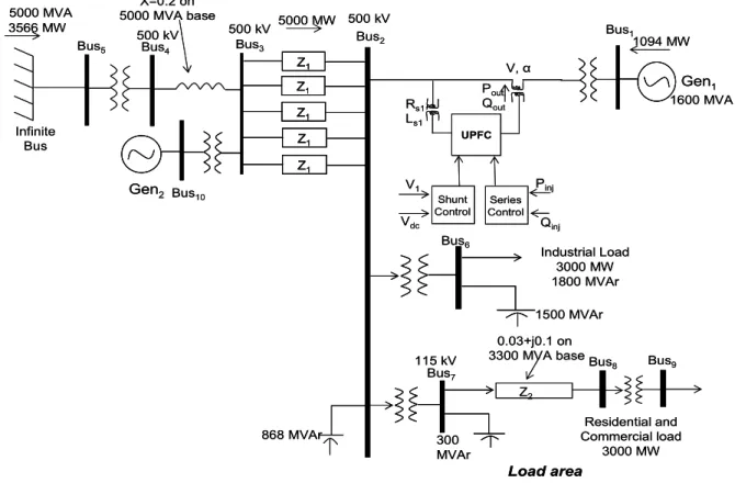
Bus1 Gen1 1094 MW 1600 MVA Z2 Bus6 Bus7 Bus8 Bus9 Industrial Load 3000 MW 1800 MVAr 1500 MVAr 115 kV 0.03+j0.1 on 3300 MVA base 300 MVAr Residential and Commercial load 3000 MW Load area Bus3 Bus4 Bus5 Bus10 Gen2 Bus2 868 MVAr 500 kV 5000 MW 500 kV X=0.2 on 5000 MVA base 500 kV 3566 MW 5000 MVA Infinite Bus V, α Qinj UPFC Shunt Control Series Control Pout, Qout Rs1, Ls1 V1 Vdc Pinj Z1 Z1 Z1 Z1 Z1 Bus1 Gen1 1094 MW 1600 MVA Z2 Bus6 Bus7 Bus8 Bus9 Industrial Load 3000 MW 1800 MVAr 1500 MVAr 115 kV 0.03+j0.1 on 3300 MVA base 300 MVAr Residential and Commercial load 3000 MW Load area Bus3 Bus4 Bus5 Bus10 Gen2 Bus2 868 MVAr 500 kV 5000 MW 500 kV X=0.2 on 5000 MVA base 500 kV 3566 MW 5000 MVA Infinite Bus V, α Qinj UPFC Shunt Control Series Control Pout, Qout Rs1, Ls1 V1 Vdc Pinj Z1 Z1 Z1 Z1 Z1 Z1 Z1 Z1 Z1 Z1
Fig. 1. Multimachine power system with a UPFC installed between buses 1 and 2.
II. MULTI MACHINE POWER SYSTEM
For studying the control of a UPFC in a multimachine power system, the setup shown in Fig.1 is simulated in the PSCAD/EMTDC environment. The power system consists of two synchronous generators Gen1 and Gen2 of ratings
1600MVA and 2200MVA respectively along with exciters and governors; and two loads, one of value P (real power) =3000 MW, Q (reactive power) = 1800 MVAR and the other of value P = 3000 MW, Q = 300 MVAR. The third generator is the infinite bus. The parameters of the system in Fig. 1 are given in [14].
III. UNIFIED POWER FLOW CONTROLLER
Unified power flow controller is a generalized synchronous voltage source, represented at the fundamental frequency by voltage phasor V with controllable magnitude V (0≤ V ≤
Vmax) and angle α (0≤α≤ 2π), in series with the transmission line. The UPFC consists of two voltage-sourced inverters. These back-to-back inverters are operated from a common DC link provided by a DC storage capacitor. This arrangement functions as an ideal ac-to-ac power inverter in which the real power can freely flow in either direction between the ac terminals of the two inverters, and each inverter can independently generate (or absorb) reactive power at its own ac output terminal.
The series inverter provides the main function of the UPFC by injecting a voltage V with controllable magnitude V and phase angle α in series with the line via an insertion transformer. This injected voltage acts essentially as a
synchronous ac voltage source. The transmission line current flows through this voltage source resulting in reactive and active power exchange between it and ac system. The inverter generates the reactive power exchanged at the ac terminal internally. The active power exchanged at the ac terminal is converted into dc power, which appears at the DC link as a positive or negative real power demand.
The basic function of shunt inverter is to supply or absorb the real power demanded by series inverter at the common DC link to support the real power exchange resulting from series voltage injection. This DC link demand of series inverter is converted back to ac by shunt inverter and coupled to the transmission line bus via a shunt-connected transformer. In addition to this the shunt inverter can also generate or absorb controllable reactive power, if it is desired and thereby provides independent shunt reactive compensation for the line. The three main control parameters of UPFC are magnitude (V), angle (α) and shunt reactive current control of real and reactive power can be achieved by injecting series voltage with appropriate magnitude and angle. This injected voltage is transformed into dq reference frame, which is split into Ed and Eq. These coordinates can be used to control the power flow.
The controllers for UPFC shunt and series branch VSIs are described below.
A. Shunt Branch Control
Control of the shunt inverter is achieved by varying the shunt inverter voltage active and reactive components Epd and Epqappropriately. The shunt control consists of regulating the bus voltage at the point of contact of shunt VSI and the
capacitor dc voltage. The shunt controller structure is shown in Fig. 2. The difference between the bus voltage V1 and its reference value V1ref is fed to a PI controller to obtain Epd and the difference between the capacitor voltage Vdc and its reference value Vdcref is fed to another PI controller to obtain Epq. Epd and Epq are then used to generate the modulation index k1 and phase angle α1for the shunt inverter.
Vdcref Vdcerr V1ref V1 Verr Vdc 1 1 1 p sh sh K T s + Shunt Inverter PWM Shunt Inverter PWM 2 2 1 1 1 tan pd pq dc pq pd E E k V E E α − + = = 2 2 1 p sh sh K T s + Epq Epd Σ Σ Σ 3 1 sh T s Vdcref Vdcerr V1ref V1 Verr Vdc 1 1 1 p sh sh K T s + Shunt Inverter PWM Shunt Inverter PWM Shunt Inverter PWM Shunt Inverter PWM 2 2 1 1 1 tan pd pq dc pq pd E E k V E E α − + = = 2 2 1 p sh sh K T s + Epq Epd ΣΣ ΣΣ ΣΣ 3 1 sh T s
Fig. 2. UPFC shunt branch control – PI controllers for the bus voltage and capacitor dc voltage regulation.
B. Series Branch Control
The three-phase line currents at the secondary side of the insertion transformer (series VSI voltage injection onto the line) is decomposed into its direct component, id, and its quadrature component, iq. These actual signals (id and iq)and the reference d-q current signals (id* and iq*) are compared respectively, as shown in Fig. 3. The error signals Iderr and Iqerr are then passed through the PI-regulator to get the output signals Ed and Eq which are then passed through a limiter and are used in the calculation of modulation index k2 and α2.
Idref Σ Σ Id Iqref Iq Iderr Iqerr Shunt Inverter PWM Series Inverter PWM 2 2 2 1 2 tan d q dc q d E E k V E E α − + = = 1 1 1 p se se K T s + Ed Eq 2 2 1 p se se K T s + Idref ΣΣ Σ Id Iqref Iq Iderr Iqerr Shunt Inverter PWM Series Inverter PWM Shunt Inverter PWM Series Inverter PWM 2 2 2 1 2 tan d q dc q d E E k V E E α − + = = 1 1 1 p se se K T s + Ed Eq 2 2 1 p se se K T s +
Fig.3. UPFC series branch control – PI controllers for active and reactive power control.
IV. PARTICLE SWARM OPTIMIZATION
Particle swarm optimization is a form of evolutionary computation technique (a search method based on natural systems) developed by Kennedy and Eberhart [15-17]. PSO like a genetic algorithm (GA) is a population (swarm) based optimization tool. However, unlike in GA, particles/individuals are not eliminated from the population from one generation to the next. One major difference
between particle swarm and traditional evolutionary computation methods is that particles’ velocities are adjusted, while evolutionary individuals’ positions are acted upon; it is as if the “fate” is altered rather than the “state” of the particle swarm individuals [17].
The system initially has a population of random solutions. Each potential solution, called particle, is given a random velocity and is flown through the problem space. The particles have memory and each particle keeps track of previous best position and corresponding fitness. The previous best value is called as pbest. Thus, pbest is related only to a particular particle. It also has another value called gbest, which is the best value of all the particles pbest in the swarm. The basic concept of PSO technique lies in accelerating each particle towards its pbestand the gbest locations at each time step. Acceleration has random weights for both pbestand gbest locations.
Fig. 4 illustrates briefly the concept of PSO, where Pk is current position, Pk+1 is modified position, Vini is initial velocity, Vmod is modified velocity, Vpbest is velocity considering pbest and Vgbest is velocity considering gbest.
(i) Initialize a population (array) of particles with random positions and velocities of d dimensions in the problem space.
(ii) For each particle, evaluate the desired optimization fitness function in d variables.
(iii)Compare particle’s fitness evaluation with particle’s pbest. If current value is better than pbest, then set pbest value equal to the current value and the pbest location equal to the current location in d-dimensional space.
Y X k
P
1 + kP
pbestV
gbestV
modV
iniV
Y X kP
1 + kP
pbestV
gbestV
modV
iniV
Fig. 4 Concept of changing a particle’s position in PSO [18].
(iv)Compare fitness evaluation with the population’s overall previous best. It the current value is better than gbest, then reset gbestto the current particle’s array index and value. (v) Change the velocity and position of the particle according
to (1) and (2) respectively. Vid and Xid represent the velocity and position of ith particle with d dimensions respectively and, rand1 and rand2 are two uniform random functions. ) X G ( rand c ) X P ( rand c V w V id bestid 2 2 id bestid 1 1 id id − × × + − × × + × = (1)
X
id=
X
id+
V
id (2) (vi)Repeat step (ii) until a criterion is met, usually asufficiently good fitness or a maximum number of iterations/epochs.
PSO has many parameters and these are described as follows: w called the inertia weight controls the exploration
and exploitation of the search space because it dynamically adjusts velocity. Local minima are avoided by small local neighborhood, but faster convergence is obtained by larger global neighborhood and in general, global neighborhood is preferred. Synchronous updates are more costly than the asynchronous updates.
Vmaxis the maximum allowable velocity for the particles i.e. in case the velocity of the particle exceeds Vmax then it is reduced to Vmax. Thus, resolution and fitness of search depends on Vmax. If Vmax is too high, then particles will move beyond good solution and if Vmax is too low, then particles will be trapped in local minima. c1 and c2 termed as cognition and social components respectively are the acceleration constants which changes the velocity of a particle towards pbest and gbest (generally somewhere between pbest and gbest). Velocity determines the tension in the system. A swarm of particles can be used locally or globally in a search space. In the local version of the PSO, the gbest is replaced by the lbest and the entire procedure is same.
V. DESIGN OF OPTIMAL CONTROLLER PARAMETERS
USING PSO
In the UPFC, there are two proportional gains (Ksh1 and Ksh2) and three integral time constants (Tsh1, Tsh2 and Tsh3) in the shunt VSI controls; and there are two proportional gains (Kse1 and Kse2) and two integral time constants (Tse1 and Tse2) in the series VSI controls. The challenge is to determine all these four gains and five time constants for the UPFC to provide optimal damping during transient conditions such as three phase faults. In order to do this for the power system in Fig. 1, the speed deviation of generators Gen1 and Gen2 are
used as the measure of performance of the shunt and series VSI controls.
To arrive at the nine optimal parameters using the particle swarm optimization, five PSO particles are selected each providing a stable dynamic and transient UPFC control. The PSO algorithm minimizes the following cost function.
(
)
(
)
(
)
20000 2 2 1 2 0 ( ) ( ) t Cost ω t ω t = =∑
∆ + ∆ (3) Where ∆ω1 and ∆ω2 are the speed deviations of generators Gen1 and Gen2 respectively, t represents the simulation timesteps in PSCAD. The cost is calculated in the first two seconds of the fault.
VI. SIMULATION RESULTS
The multimachine power system in Fig. 1 has the operating points for Gen1: P1 = 1094 MW, Q1 = -94 MVAR and Gen2: P2 = 1500 MW, Q2 = 0 MVAR. At this operating point, the nine combined parameters of the UPFC shunt and series branch controllers are optimized for transient stability using the PSO algorithm. The five PSO particles initial settings for a given run are shown in Table I. The PSO parameters used in the simulation are w = 0.8 and c1 = c2 = 2. After ten iterations with the PSO algorithm, the optimal parameters (gbest) are found and shown in the last row of Table I. The PSO process was carried out over 20 trial runs. Overall, parameters close to the
optimal values in Table I are obtained on the various trial runs. This observation is coherent with literature [19].
TABLEI
PSO PARTICLES’ INITIAL PARAMETERS AND THE FINAL OPTIMAL PARAMETERS DURING ONE OF THE TRIAL RUNS
0.01 0.01 0.1 Optimal Parameters 0.1 1 0.01 1 2 0.04 0.5 0.01 1.0 5 0.1 4.5 0.8 1 2 0.04 0.5 0.01 1.0 4 0.1 4.5 0.1 3.5 2 0.04 0.5 0.01 1.0 3 0.1 4.5 0.1 3.5 0.5 0.04 0.5 0.01 1.0 2 0.1 4.5 0.1 3.5 0.5 0.04 0.8 0.01 1.0 1 Tse2 Pse2 Tse1 Pse1 Tsh3 Tsh2 Psh2 Tsh1 Psh1 Particles 4.02 0.59 1.0 0.01 1.05 0.01 Optimal Parameters 0.1 1 0.01 1 2 0.04 0.5 0.01 1.0 5 0.1 4.5 0.8 1 2 0.04 0.5 0.01 1.0 4 0.1 4.5 0.1 3.5 2 0.04 0.5 0.01 1.0 3 0.1 4.5 0.1 3.5 0.5 0.04 0.5 0.01 1.0 2 0.1 4.5 0.1 3.5 0.5 0.04 0.8 0.01 1.0 1 Tse2 Pse2 Tse1 Pse1 Tsh3 Tsh2 Psh2 Tsh1 Psh1 Particles 2.72 0.01 0.01 0.1 Optimal Parameters 0.1 1 0.01 1 2 0.04 0.5 0.01 1.0 5 0.1 4.5 0.8 1 2 0.04 0.5 0.01 1.0 4 0.1 4.5 0.1 3.5 2 0.04 0.5 0.01 1.0 3 0.1 4.5 0.1 3.5 0.5 0.04 0.5 0.01 1.0 2 0.1 4.5 0.1 3.5 0.5 0.04 0.8 0.01 1.0 1 Tse2 Pse2 Tse1 Pse1 Tsh3 Tsh2 Psh2 Tsh1 Psh1 Particles 4.02 0.59 1.0 0.01 1.05 0.01 Optimal Parameters 0.1 1 0.01 1 2 0.04 0.5 0.01 1.0 5 0.1 4.5 0.8 1 2 0.04 0.5 0.01 1.0 4 0.1 4.5 0.1 3.5 2 0.04 0.5 0.01 1.0 3 0.1 4.5 0.1 3.5 0.5 0.04 0.5 0.01 1.0 2 0.1 4.5 0.1 3.5 0.5 0.04 0.8 0.01 1.0 1 Tse2 Pse2 Tse1 Pse1 Tsh3 Tsh2 Psh2 Tsh1 Psh1 Particles 2.72
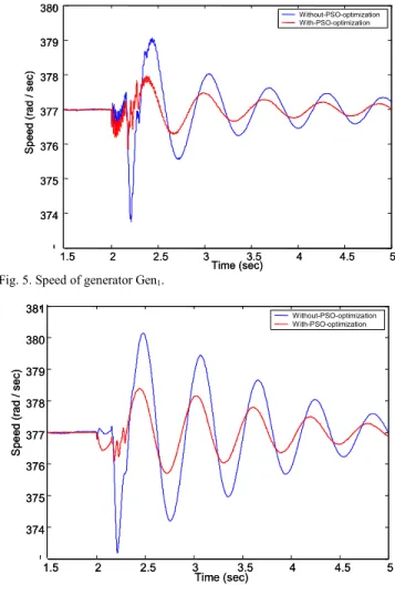
Figs. 5 and 6 compare the speed of Gen1 and Gen2
respectively, obtained with the parameters of particle 1 and with that obtained from the optimal parameters determined by PSO for 150 ms three phase short circuit applied at bus 4.
1.5 2 2.5 3 3.5 4 4.5 5 374 375 376 377 378 379 380 Time (sec) Sp eed ( rad / s ec) Without-PSO-optimization With-PSO-optimization 1.5 2 2.5 3 3.5 4 4.5 5 374 375 376 377 378 379 380 Time (sec) Sp eed ( rad / s ec) Without-PSO-optimization With-PSO-optimization
Fig. 5. Speed of generator Gen1.
1.5 2 2.5 3 3.5 4 4.5 5 374 375 376 377 378 379 380 381 Time (sec) S pee d ( rad / s ec ) Without-PSO-optimization With-PSO-optimization 1.5 2 2.5 3 3.5 4 4.5 5 374 375 376 377 378 379 380 381 Time (sec) S pee d ( rad / s ec ) Without-PSO-optimization With-PSO-optimization
Fig. 6. Speed of generator Gen2.
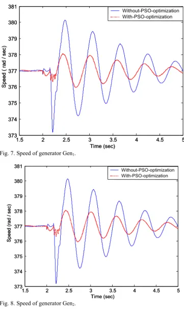
The speed response during a 150 ms three phase short circuit applied at bus 4 obtained with the parameters of particle 5 and with that obtained from the optimal parameters
(gbest) determined by PSO are shown in Figs. 7 and 8 for generators Gen1 and Gen2 respectively. In both cases, the
controllers with optimal parameters determined by the PSO give better damping of the speed deviations of the generators. This performance was achieved with the cost function given in (3). The objective function can be modified to include setting time.
The PSO based UPFC controller parameter tuning for large power systems in real-time can be based on snapshots of the transient performance of power system under some disturbance and running the PSO optimization on a fast DSP processor. Every time the operating conditions change, an optimization of PI controllers’ parameters may be necessary.
1.5 2 2.5 3 3.5 4 4.5 5 373 374 375 376 377 378 379 380 381 Time (sec) S peed ( r ad / s ec ) Without-PSO-optimization With-PSO-optimization 1.5 2 2.5 3 3.5 4 4.5 5 373 374 375 376 377 378 379 380 381 Time (sec) S peed ( r ad / s ec ) Without-PSO-optimization With-PSO-optimization
Fig. 7. Speed of generator Gen1.
1.5 2 2.5 3 3.5 4 4.5 5 373 374 375 376 377 378 379 380 381 Time (sec) S pee d ( rad / sec) Without-PSO-optimization With-PSO-optimization 1.5 2 2.5 3 3.5 4 4.5 5 373 374 375 376 377 378 379 380 381 Time (sec) S pee d ( rad / sec) Without-PSO-optimization With-PSO-optimization
Fig. 8. Speed of generator Gen2.
VII. CONCLUSION
This paper has shown based on some preliminary studies that particle swarm optimization can be applied to obtain the optimal parameters for the unified power flow controller shunt and series voltage source inverter PI controls. It is anticipated that the cost function can be modified further to include other constraints such as settling time and/or rise time in addition to area under a curve. This concept can be extended to include in
the optimization of the controller parameters other UPFC functions such as to maximize reactive and real power compensation, minimize voltage deviation at the shunt bus for multiple operating points and disturbances. Future work also involves benchmarking the PI controller parameters obtained by PSO with those from other methods.
VIII. REFERENCES
[1] R. M. Mathur and R. K. Varma., Thyristor-Based FACTS Controllers
for Electrical Transmission Systems, IEEE Press and John Wiley &
Sons, Inc, ISBN 0-471-29858-1.
[2] L. Chunlei, S. Hongbo and D. C. Yu, , “A novel method of power flow analysis with unified power flow controller (UPFC)”, IEEE Power
Engineering Society Winter Meeting, vol. 4, pp. 2800 -2805, 2000.
[3] N. G. Hingorani and L. Gyugyi, Understanding FACTS Concepts and
Technology of Flexible AC Transmission Systems, ISBN 0-7803-3455-8,
1999.
[4] G. K. Venayagamoorthy and R. G Harley, "Two separate continually online-trained neurocontrollers for excitation and turbine control of a turbogenerator", IEEE Transactions on Industry Applications, vol. 38, no. 3, May/June 2002, pp. 887 -893.
[5] P. K. Dash, S. Mishra and G. Panda, “A radial basis function neural network controller for UPFC”, IEEE Transactions on Power Systems, vol. 15, no.. 4, 2000, pp. 1293 - 1299.
[6] G. K. Venayagamoorthy, R. G Harley and D. C. Wunsch, “Implementation of Adaptive Critic Based Neurocontrollers for Turbogenerators in a Multimachine Power System”, IEEE Transactions
on Neural Networks, vol. 14, no. 5, September 2003, pp. 1047 - 1064.
[7] J. W. Park, R. G. Harley and G. K. Venayagamoorthy, "New Internal Optimal Neurocontrol for a Series FACTS Device in a Power Transmission Line", Neural Networks, vol. 16, no. 5-6, July 2003, pp. 881-890.
[8] Y. L. Abdel-Magid, M. A. Abido, S. Al-Baiyat and A. H. Mantawy, “Simultaneous stabilization of multi machine power systems via genetic algorithms,” IEEE Trans. Power system, pp. 1428-1439, 1999.
[9] M. A. Abido, “A novel approach to conventional power system stabilizer design using tabu search,” Int. Journal Electrical Power
Energy, pp.443-454, 1999.
[10] M. A. Abido, “Robust design of multimachine power system stabilizers using simulated annealing”, IEEE Trans. Energy Conversion, vol. 15, pp. 297-304, Sept. 2000.
[11] D. B. Fogel, Evolutionary Computation Toward a New Philosophy of
Machine Intelligence: New York: IEEE, 1995.
[12] A Coello Coello Carlos and M.S Lechuga, “MOPSO: A proposal for multiple objective particle swarm optimization,” Proceedings of
International Conference on Evolutionary Computation, pp. 1051-1056.
2002.
[13] V.G Gudise and G.K Venayagamoorthy, "Comparison of particle swarm optimization and backpropagation as training algorithms for neural networks," IEEE Swarm Intelligence Symposium, pp.110-117, April, 2003.
[14] C. W. Taylor, N. J. Balu, and D. Maratukulam, Power System Control
and Stability, McGraw-Hill companies, EPRI Power System engineering
Series, ISBN 0070631840, 1993.
[15] James Kennedy and R. Eberhart, "Particle swarm optimization", IEEE
International Conf. on Neural Networks, Perth, Australia. Vol. 4, pp.
1942–1948. Dec 1995.
[16] Y. Shi and R. Eberhart, "Empirical study of particle swarm optimization", Proceedings of the 1999 Congress on Evolutionary
Computation, CEC 99, Vol. 3, 1999.
[17] J. Kennedy, R. C. Eberhart and Y. Shi, Swarm Intelligence, Morgan Kaufmann Publishers, 2001.
[18] H. Yoshida, Y. Fukuyama, S. Takayama and Y. Nakanishi., “A particle swarm optimization for reactive power and voltage control in electric power systems considering voltage security assessment.”Proceedings of
the IEEE SMC '99 Conf.. Vol. 6, pp. 497 -502, 1999.
[19] S. Doctor, G.K. Venayagamoorthy, V.G.Gudise, “Optimal PSO for Collective Robotic Search Applications”, IEEE Congress on
Evolutionary Computation, Portland, OR, USA, June 20 – 23, 2004, pp.
IX. BIOGRAPHIES
Ganesh Kumar Venayagamoorthy (M’97, SM’02) received the B.Eng. (Honors) degree with a first class honors in Electrical and Electronics Engineering from the Abubakar Tafawa Balewa University, Bauchi, Nigeria, and the MScEng and PhD degrees in Electrical Engineering from the University of Natal, Durban, South Africa, in March 1994, April 1999 and February 2002, respectively. He was a Senior Lecturer at the Durban Institute of Technology, South Africa prior to joining the University of Missouri-Rolla (UMR), USA as an Assistant Professor in the Department of Electrical and Computer Engineering in May 2002. He is the Director of the Real-Time Power and Intelligent Systems Laboratory at UMR. His research interests are in computational intelligence, power systems, evolvable hardware and signal processing. Dr. Venayagamoorthy has attracted in excess of $ 1 million in research funding from external sources since joining UMR. He has published over 130 papers in refereed journals and international conferences. Dr. Venayagamoorthy is the 2005 IEEE Industry Application Society (IAS) Outstanding Young Member award recipient, a 2004 NSF CAREER award recipient, the 2004 IEEE St. Louis Section Outstanding Young Engineer, the 2003 International Neural Network Society (INNS) Young Investigator award recipient, a 2001 recipient of the IEEE Computational Intelligence Society (CIS) W. J. Karplus summer research grant and the recipient of five prize papers with the IEEE IAS and IEEE CIS. He is an Associate Editor of the IEEE Transactions on Neural Networks. He is a Senior Member of the South African Institute of Electrical Engineers, a Member of INNS and the American Society for Engineering Education. He is currently the IEEE St. Louis CIS and IAS Chapter Chair, theChair of the task force on Intelligent Control Systems and the Secretary of the Intelligent Systems subcommittee of IEEE Power Engineering Society.