91
Prototype System Control Car Garage Based Microcontroller
ATMEGA 8535
Sumardi Sadi
Lecturer of the Faculty of Engineering, University of Muhammadiyah Tangerang Jl. Perintis Kemerdekaan I No. 33 Cikokol Kota Tangerang-Banten -Indonesia
Email : [email protected] Abstract
In this study have designed a prototype of a microcontroller-based control car garage ATMEGA 8535. The workings of this car garage can be controlled in three ways. First by using the remote control, both by means of pressing the keypad, the third by using infrared sensors. The first is the use of remote control, remote control that has been made to control the garage door to open and close the car from a maximum distance of 30 meters. The second is the use of control keypad, keypad is used to control the opening and closing car garage in close proximity so that the user can embroider the keypad button corresponding to the data / bits that have been specified. The third is the use of control infrared sensors, infrared sensors can control car garage open and close automatically to the car objects directly.
The remote control as the control system works by encoding the data bits / binary sent and received microcontroller ATMEGA 8535 after passing the lopping on the microcontroller. While the door sensor control system uses an infrared LED and photodiode transceiver as receiver for detecting cars that will exit / entry garage, so when detected car passing through the infrared sensor, the control system will open car garage. In addition to using the remote control system such as control, keypad and infrared sensors, controllers car garage is a password, so that car garage open and close system can still be used even if not using the remote.
Keyword : ATmega8535 microcontroller, remote control, keypad, infrared sensors, car garage, infra red LED, photodiode.
Introduction
Developments in science and technology has increased very rapidly. This situation impact on all areas of human life. One is the industrial field. A wide variety of industry is growing rapidly along with the demands of the development of science and technology are so advanced both heavy industry and light industry. Everyone who has a personal vehicle certainly make every effort to keep the vehicle has. Start of manually applying security system in the form of a padlock, until the safety system is automated. Specifically for each user type four-wheeled private vehicles namely cars, the owner tried to keep his vehicle when he was in the house by adding additional buildings such as a garage at home. The garage is a place to store the car in order to avoid theft or to protect the car against the weather hot sun, rain or dew at night so as to avoid the car containing the acid dew that age of the vehicle can be longer because it can hinder the process of rust on the car body or the parts that are exposed to moisture and water. Garage size depends on the size of the vehicle.
One of the routines is often done is open the closed door of the garage, the garage door opening and closing process is possible for some people more easily done manually by pulling or sliding the garage door without having to use the automated system or use a remote control system, but on the other hand there are a lot of trouble if by the time we have to open and close the door in a state does not have much time, rain, or in a state that does not allow us to draw / shift the garage door. We also longer take the time if you have to get down from the vehicle to open the garage door when they want to enter the vehicle. With the garage door opening systems remotely is expected to complement the human need for facilities, comfort and security at the garage door.
Literature Review
2.1 Microcontroller ATmega8535
The microcontroller is a programmable IC repeatedly, either written or deleted (Agus bejo, 2007). Typically used for automatic and manual control on electronic devices.
92 `
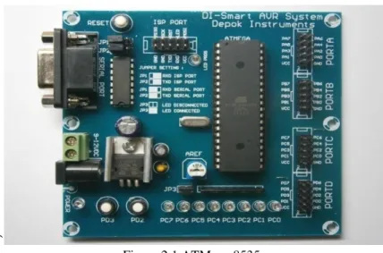
Figure 2.1 ATMega 8535 Source : Basic of Microcontroller 2010
In recent years, the microcontroller is very widely used, especially in controlling the robot. Along with the development of electronics, microcontroller made more compact with the programming language that is also changed. One is the AVR microcontroller (Alf and Vegard's RISC processor) ATmega8535 using RISC technology (Reduce Instruction Set Computing) which programs run faster because it only takes one clock cycle to execute an instruction program. In general, the AVR can be grouped into 4 classes, ATtiny, family AT90Sxx, ATmega family, and AT86RFxx. Basically what distinguishes each class is memory, peripherals, and function. In terms of architecture and instruction are used, they can be said to be almost the same.
ATmega8535 AVR microcontroller features a fairly complete. ATmega8535 AVR microcontroller is equipped with an internal ADC, internal EEPROM, Timer / Counter, PWM, analog comparator, etc. So with complete facilities allows us to learn AVR microcontroller family with easy and efficient, and can develop creativity using ATmega8535 microcontroller.
Features that are owned by the microcontroller ATmega8535 is as follows: 1. Channel I / O as many as 32 pieces, ie port A, port B, port C, and port D. 2. The internal ADC many as 8 channels.
3. Three Timer / Counter with benchmarking capabilities. 4. The CPU consists of 32 registers.
5. 512 bytes SRAM.
6. Flash memory is 8 kb with the ability to Read While Write. 7. Port SPI interface
8. 512 bytes EEPROM can be programmed while operating. 9. Interface analog comparator.
10. Port USART for serial communications.
11. System 8-bit RISC-based microprocessor with a maximum speed of 16 MHz. 12. And others.
93
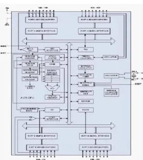
Figure 2.2 Functional Block Diagram ATMega8535 Source : Basic of Microcontroller 2010
2.2 DC motors
Figure 2.3 DC motors
Source: Prototype Design of Control Gate and Garage Using Modulation FSK (Frequency Shift Keying)
DC motor is a motor of which is controlled by the direct current (DC). DC motors require a supply voltage to the coil in the direction of the terrain to be converted into mechanical energy. Field coil in a DC motor called the stator (the part that does not rotate) and the rotor coil called the anchor (rotating parts). If there is a round in the anchor coil in the magnetic field, then there will be a voltage (EMF) changing direction at every half rotation, so an alternating voltage. The working principle of the direct current voltage is the reverse phase of the wave which has a positive value by using a commutator, so current that reverses direction with the anchor coil rotates in a magnetic field. The simplest form of a motor having a winding coil that can rotate freely between the poles of a permanent magnet.
94 2.3 DC motor driver L293D
Figure 2.4 IC L293D
Source: STMikroelektronics Datasheet L293D / L293Dd, 2003
Figure 2.5 DC motor driver on the circuit
Source: Prototype Design of Control Gate and Garage Using Modulation FSK (Frequency Shift Keying) Drivers of motor is used to drive a DC motor using microcontroller. Current that can be accepted or issued by the microcontroller is very small (in milliamps) so that the microcontroller can drive a DC motor required a motor driver circuit that is capable of flowing currents up to several amperes. DC motor driver circuit may include a series of transistors, relays, or IC (Integrated Circuit). Driver circuit that is commonly used is the IC L293D. IC L293D contains 4-channel driver with a current capability of 600mA per channel. IC L293D working voltage of 6 volts to 36 volts and no recurring impulse current of 1.2 amperes maximum. L293D IC pin configuration is shown in Figure 2.4.
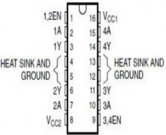
Figure 2.6. Pin Configuration IC L293D
source : STMikroelektronics DatasheetL293D/ L293Dd, 2003
L293D driver IC which has the ability to drive a DC motor 2A current and maximum voltage of 40 Volts DC to the canals. Enable pin A and B for controlling the path or speed motors, pin Input 1 to 4 to control the direction of rotation. Enable pin VCC 5 volt given to full speed and Pulse Width Modulation (PWM) for the rotational speed varies depending on the level of highnya.
95
Figure 2.7 Illustration of Pulse Width Modulation
Source: Prototype Design of Control Gate and Garage Using Modulation FSK (Frequency Shift Keying) From Figure 2.6 can be explained if desired full speed then given 5 Volt constant, if desired speed varies the pulse width given highs and lows of his varied. One period of the pulse has the same time so that in the example above, the motor speed will change from half full speed to near full speed. Typically used pulse width within a few milliseconds for example 2 ms. In L293D chip, to control the direction of rotation of the motor used method of the combination of H-bridge transistors, so the current flows such methods kemotor polarity can be set to provide the logic to transistor Q1 to Q4. The arrangement is such truth table, high condition for all inputs is not permitted because it would lead to all active and will damage the transistor transistor because it automatically flows from the collector of Q1 and Q2 directly flowing into Q2 Q3 san so very large currents without the burden of a DC motor.
2.4 SPC IR TRANSCEIVER
Smart Peripheral Controller / SPC INFRARED TRANSCEIVER is a tool sender and receiver data via infrared ray media with 4 common protocol used is SONY, PANASONIC, PHILIPS, and Raw Data. To communicate with SPC supplied INFRARED TRANSCEIVER 3 forwarding of data communication interface that allows users to select the desired interface. Examples of applications of SPC INFRARED TRANSCEIVER is for wireless data exchange (wireless communication), remote transmitter, remote receiver, remote control data reader, and so on.
Figure 2.8 Sensor Infrared Transceiver Source: Manual SPC IR TRANSCEIVER
2.5 IR Sensor Detector
IR Sensor Detector is a sensor that works when there is a detected object in the way. In its application, the IR Sensor Detector in the form of an infrared LED as a transmitter and a photodiode as Reciver.
2.5.1 LED Infrared
Infrared is electromagnetic radiation of a wavelength longer than visible light, but shorter than radio waves radiation. One type of infrared sensors that use a combination of infrared LED as a transmitter and a phototransistor as the receiver. LED is a semiconductor material that emits incoherent monochromatic light when given a forward voltage. LED development began with infrared instruments made with galliumarsenide. Essentially infrared light is electromagnetic radiation of a wavelength longer than visible light, but shorter than radio wave radiation, in other words infra is the color of visible light with the longest wave, which is about 700 nm to 1 mm.
96
Figure 2.9 LED infrared
Source : Prototype Design of Control Gate and Garage Using Modulation FSK (Frequency Shift Keying)
2.5.2 Photodioda
LED light arise as a result of the merger of electrons and holes at the junction between the two types of semiconductor in which each merger is accompanied by the release of energy. On the use of infrared LEDs can be activated with a DC voltage for transmission or proximity sensor, and with teganganAC (30-40 KHz) for transmission or remote sensor.
Figure 2.10 Photodiode and LED Infrared
Source : Prototype Design of Control Gate and Garage Using Modulation FSK (Frequency Shift Keying) Photodiode is a type of diode that the resistance change when the light falling on the diode fluctuate intensity. In a very large dark prisoner value until practically no current is flowing. The stronger the light falling on the diode, the smaller the value of prisoners, so the greater the current flowing. If the pn junction photodiode reverse voltage is irradiated, then the flow will vary linearly with the increase of light flux imposed at the junction. Photodiode made of semiconductor materials. Usually used is silicon (Si) or gallium arsenide (GaAs), and others including indium antimonide (InSb), indium arsenide (InAs), lead selenide (PbSe), and tin sulfide (PBS). These materials absorb light through the characteristic wavelength range, for example: 250 nm to 1100 nm for silicon, and 800 nm to 2.0 lm for GaAs. Photodiode is a type of diode that serves to detect light. Unlike the conventional diode, electronics components, this will convert light into electric current. Light which can be detected by a photodiode is ranging from infrared light, visible light, ultra-violet to X-rays. Photodiode applications ranging from vehicles on public roads counter automatically, the camera's light meter as well as some of the equipment in the medical field.
Photodiode is used as a component detecting the presence or absence of light and can be used to form an accurate measuring instrument that can detect light intensity under 1PW / cm2 until the intensity above 10 mW / cm2. Photodiode has a low resistance in the forward bias conditions, we can take advantage of this photodiode reverse bias condition in which the resistance of the photodiode will decrease with the intensity of incoming light. This component has a better sensitivity compared to diodapeka light. This is because electrons generated by photons of light at this junction is injected at the base and reinforced at the collector. However, the response time of the photo transistor will generally slower than the light-sensitive diodes. If the photo diode is not exposed to light, then there is no current flowing to the comparator circuit, if the photodiode is exposed to light, the photodiode will be as stress, so Vcc and photodiode arranged series, consequently there is current flowing to the comparator circuit.
97 2.6 Keypad
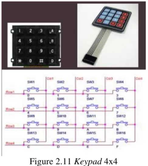
Keypad required to interact with the system at the time of setting the set-point of a feedback control at the time the program is still running. Actually each program has a different way to interact with the system. Even for each programming keypad can be hardwere different. This is due to different purposes. 4x4 keypad is more often used by programming. Besides hardwerenya easy, softwerenya also not difficult. Basically keypad 4x4 is 16 push-buttons are arranged in Matrixs.
Figure 2.11 Keypad 4x4
Source: Access Function Keypad For AVR Microcontroller With the C language (code vision avr)
2.7 LCD
Figure 2.12. LCD (Liquid Crystal Display)
Source: Proteus Professional Module for Digital Simulation and Microcontroller circuit
LCD (Liquid Crystal Display) is a form of liquid crystal that will change color when subjected to stress him. Display form 5 x 7 dot matrix, so the fonts that can be displayed will be more and better resolution compared to seven segment. Input is needed to control this module form termutipleks data bus 25 with 3-bit address bus and control signals. LCD LCD used is of type M1632, where the LCD image is shown in Figure 2.10.
Figure 2.13. LCD M1632
Source: Arduino Uno microcontroller module Train To Control Room Temperature Using Temperature Sensor, Fan and Liquid Crystal Display
M1632 LCD type, has the following characteristics:
98 character dot matrix display with 5 x 7.
b) The character generator ROM with 192 types of characters. c) The character generator RAM with 8 types of character.
d) Equipped with an additional function: display clear and cursor home,
thedisplay on / off, cursor on / off, display character blink, cursor shift and display shift. e) The power supply +5 volts.
3. PROTOTYPE DESIGN TOOLS
In the design of this automatic garage simulation, will be divided into 3 parts: 1. The design of mechanical
2. Design Hardware Design Software
3.1 Design of Mechanical
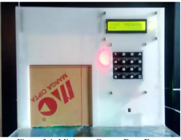
In its design, made miniature garage for ease of present. With a height of 22 cm and a length of 30 cm. However, this tool can be used as a simulation of the actual tool.
Figure 3.1 Miniature Garage Door Front
Figure 3.2 Miniature Garage Door Looks From Within and Components 3.2 Design Hardware
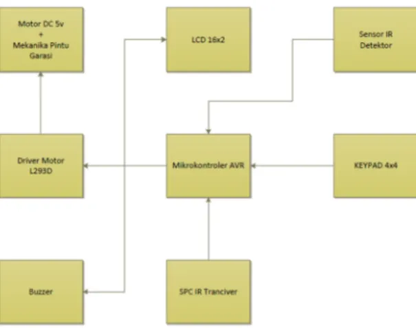
In this design using a microcontroller as the central control components to drive the replica garage. Here's a picture block diagram of a system that will be realized.
99
Figure 3.3 Block Diagram Overall
In the block diagram above can be explained that the garage working system controller uses three conditions. A. If the car out of the garage will fit through the sensors installed in the garage and the garage will open automatically.
B. If the car will go into the garage by pressing the remote control.
C. If the car will go in the garage is not using the remote, then the supplied keypad to enter paswort. 3.3 Work System
The way the system works garage based block diagram Figure 3.1 are as follows:
1. The entire performance of the system is controlled by a controller that works in accordance with the instructions set by the software.
2. When the system is activated, the LCD screen will show an info about the alert status of the sensor light is at a value <230dan on value> 950 door will open when a car passes a sensor located in the garage and out through the gate, and will close if the car actually passes through the sensor. For stuff that does not want such an object, animal or human that passes the sensor. Then the sensor in the setting for reading movement through 2 times. 3. If the car from the outside want to get into the garage using the remote control, then press the button and the car into the garage. To close the garage simply press the remote control back.
4. If something unexpected happens on the remote (the case of loss or misplaced remote), supplied keypad to enter a password. If the input password is correct, then the door will open and close the garage enough to pass through the sensor, the garage will be closed. But if it encountered an error in entering the password for 3 times the alarm / buzzer will sound.
3.3.1 Hardware Specifications
To create a miniature automatic garage needed some components and tools also supporting projects that can be made automatic garage.
3.3.2. ATmega8535 microcontroller circuit
Of the microcontroller which will be used in this study is a microcontroller family manufactured by Atmel ATmega, namely ATmega8535. ATmega8535 has been equipped with features that can be utilized in the development of applications on akkhir this task, among others:
1. Has the internal ADC facility that can be used to speed data conversion of 125µs at a resolution of 8-bit bit. 2. It has a timer that has been equipped with the ability to generate a PWM signal.
3. It has 3 timers (two 8-bit timers and one 16-bit timer) so that in addition to generate the PWM signal, there is still another timer to make the time slots in the interest of the development of application software.
ATmega8535 microcontroller circuit in this study will be working on the system clock of 8 MHz. The system clock is generated by a 47 MHz crystal oscillator 8 is equipped with two decoupling capacitors, each for 22 pF to stabilize the clock frequency. AVCC pin, analog voltage, the voltage source connected to VCC through a low-pass filter low-passive. AVCC will be used as the internal reference voltage to the ADC. Low-low-pass filter connected to AVCC intended that the analog supply ripple at AVCC pin small so that the internal ADC will have a high degree of precision.
100
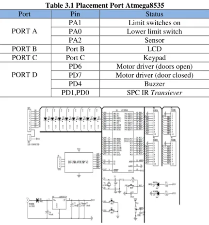
Table 3.1 Placement Port Atmega8535
Port Pin Status
PORT A
PA1 Limit switches on PA0 Lower limit switch
PA2 Sensor
PORT B Port B LCD
PORT C Port C Keypad
PORT D
PD6 Motor driver (doors open) PD7 Motor driver (door closed)
PD4 Buzzer
PD1,PD0 SPC IR Transiever
Figure 3.4 The series microcontroller ATmega8535 Source: Basic of microcontroller 2010 1.3.2. Keypad
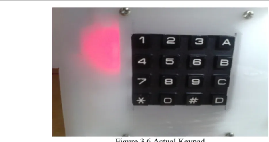
Keypad function for filling passwords, and for replacement of passwords can also be done using the keypad without changing the data that is in mikokontroler. In the circuit shown in Figure 3.4 keypad entry into mikokontroler.
101
Figure 3.6 Actual Keypad 1.3.3 LCD
LCD is used to display data from the keypad password given mikokontroler through programs created. LCD will display the status of the (S) which is a light intensity of the sensor that is in the garage, (R) is a 0/1 status which means the system using a remote opening and closing of the garage, and also to display the hidden passwords and use an asterisk (*) in order to password secrecy maintained. Figure 3.5 is a series of LCD
Figure 3.7 LCD circuit
Source: Quick Start-IO DT 4x4 Keypad
Figure 3.8 Actual LCD 1.3.3 Motor Driver
102
Figure 3.9 The circuit Motor Driver L293D
Figure 3.10 Actual L293D motor driver 3.3.5 SPC IR TRANSCEIVER
An infrared sensor that serves to open or close the garage with remote control. The following schematic drawing of SPC IR TRANSCEIVER.
Figure 3.11 Schematic circuit SPC IR TRANSCEIVER Source: Manual SPC IR TRANSCEIVER
103
Figure 3.12 Actual SPC IR TRANSCEIVER 3.3.6 Sensor Detector
The detector sensor functions as a presence detector. Here to be in detection is the car that will come out or go into the garage, where the use of these sensors are used so that the car can enter and do not overwrite the current car garage will be closed. Yamg detector sensor is used in this design uses an IR LED and photodiode as the receiver as a transceiver.
.
Figure 3.13 Schematic circuit Sensor Detector
Figure 3.14 Actual Sensor Detector 1.2 Design and Realization of Software
Design and realization of software made to set performance AVR microcontroller 8535, where the microcontroller AVR 8535 is a subsystem of brain pengandali. The software on the microcontroller serves to control the entire subsystem.
3.4.1 Software specification
104 a. Designed software created with the C language
b. The program of courses that are made using only instructions AVR microcontroller 8535.
c. Software used to write the program is CodeVision AVR. 3.4.2 Flowchart Software
Software algorithms made to simplify the programming of the entire system. Below is a flow diagram made of each system state is used in the manufacture of replica garage.
3.4.2.1 Diagram Alir sensor Detektor Explanation detector sensor is a flow diagram:
• When will the car out of the garage and passes the sensor, then the input data from the sensors will be processed two times in Luping by the microcontroller and open the garage door.
• When the car passes the sensor, the garage will be closed with delay for 2 seconds.
• But if there is something that passes through the sensor unless the car and the input data is only read by mikrokontoler only 1 time Luping eat garage will not open.
3.4.2.2 Flowchart Remote Control
Explanation flow diagram of remote control are:
In this remote control input data of keystrokes will be processed by the microcontroller and transmit binary data to command opens the gate and garage closed in accordance with the emphasis on the remote.
3.4.3.2 Flowchart Keypad
Explanation of the keypad is a flow diagram:
• using a 4-digit password and using the default rate is 1234. In entering the correct password then the garage will be open.
• And the garage will be closed when the car passes the sensor located in the garage.
• Enter the password data is read microcontroller has an error, it will be three times the limit of password input. But in 3-time passwords continue to experience errors or buzzer alarm will sound.
4. TESTING AND ANALYSIS 4.1 Microcontroller circuit testing
This circuit is the brain of the whole series. All existing circuit controlled by a series of input output this microcontroller. Mini system used IC ATMEGA 8535 with a program of reasons can be removed repeatedly - again.
Figure 4.1 Testing The Microcontroller
105
mikrokontoler ready for use. After that then made according to the need for automatic doors in one direction. Port - the port used for limit switch Porta, LDR sensors and LEDs, PortB for LCD, for Keypad PORTC and PORTD to the receiver, motor driver, and buzzer.
4.2 The test circuit DC Motor
DC motor circuit testing is done by making a simple program to turn the motor. Is to provide an input of 0 or 1 on the IC L293D of the microcontroller. If the motor can rotate mean this circuit to function properly. In this circuit the input IC L293D associated with PORTD (PD6, PD7, AVV, GND), and its output is connected to the DC motor.
Table 4.1 Truth Series of Motor Dc
Mikrokontroler Input Door Tension
PortD.6 1 0 open the garage 4,5 V
PortD.7 0 1 Closing the garage 5,7 V
By looking at the results of the above table shows that the series DC motor function and can be used. 4.3 IR sensor testing and Photodioda
In testing infrared sensors and photodiode was conducted by placing objects that may block the beam of infra-red as the tranciever. So that the infrainfra-red light output of the photodiode as the receiver can be distinguished by the time the condition is blocked and not blocked.
Figure 4.2 Passing Car When Exit Sensor Table 4.2 Output Sensor LDR Against Light Intensity The Light Output Condition Logic
Blocked 951 1 (High)
Not blocked ± 290 0 (Low)
In circumstances not blocked object, the infrared light will give the value programmed steep 290 dimikrokontroler and appears on the LCD screen. If an object blocking the IR sensor is placed and then the steep grades will increase to> 950 and the garage door will open. Once the objects are not blocking the IR sensor microcontroller calculates for 2 second to close the garage door.
106 4.4 Testing SPC IR Transceiver
In Transceiver IR sensor testing is done by knowing the distance remote signal to the sensor Infra Red tranciever.
Table 4.3 Truth Against IR Remote Transceiver
Distance Signal
5 meters Ok
10 meters Ok
20 meters Ok
30 meters Ok
Om the truth table above shows that the signal at a distance of 30 meters are able to open or close the garage door. And to position the remote can 360º in use, with a note there is no obstacle that reflects the light on the remote IR.
4.5 Testing Keypad and LCD
Since both of these components relate the tool to analyze by looking at whether the emphasis on the keypad there are problems that can make an error in the reading on the LCD.
Figure 4.3 LCD and Keypad
Both of these components can work well as a program that is given to the appropriate microcontroller.
Conclusion
Both of these components can work well as a program that is given to After going through the testing process and the data obtained from the test results, it can be concluded that:
1. From the experimental results on the instrument, to the sensor from the inside which consists of an infrared LED and photodiode can be used optimally. However, the sensor from the outside still can not be used. And for the infrared rays of light no other constraints affecting the receiver.
2. To open the motor in its development, there are still shortcomings as munutupnya door is still too fast. 3. For the remote can be used in any condition with the furthest distance ± 30 meters and 360º.
4. Open and close the garage door system can work in accordance with the algorithm embedded in the microcontroller.
References
Aang Sukendar, Martinus and Novri Tanti, 2003, Making System Automation for Machine Work Mechanism Settings Print Crackers Using Atmega Microcontroller, Journal FEMAVo. 1 No. January 1.
Ibn Nadir, Sri Ratna Sulistiyati, Agus Trisanto, 2014, Design of Model Garage with RFID-Based Microcontroller Applications, Department of Electrical Engineering, University of Lampung, Bandar Lampung, ELECTRICIAN - Journal of Electrical Engineering and Technology, Volume 8, No. 2 May.
Atmel 2010, Atmega8535 Datasheet Rev. 2466T-AVR-07/10, Publishers Atmel
Agus Bejo, 2008, C & AVR Secret Facility Language C in Microcontroller ATMega8535. Graha Science, Yogyakarta.
Saeful Ervin, 2011, Prototype Design of Control Gate and Garage Using Modulation FSK (Frequency Shift Keying), Indonesian Computer University (Thesis)
107
Budiharto Widodo, 2010, Robotics Theory + Implementation, Publisher ANDI, Yogyakarta.
Budiharto Widodo, Firman Sigit, 2010, Digital Electronics and Microprocessors, Publisher ANDI, Yogyakarta Polytechnic Caltex Riau 2011, Proteus Professional & Simulation Module Code Vision AVR, Riau
Community Service Program, 2013, Proteus Professional Module For Digital Simulation and Microcontroller circuit, State University of Yogyakarta, Yogyakarta
Rudiyana, 2010, Visualization Message Behind Vehicle Using Microcontroller, Indonesian Computer University (Thesis)
Deddy Susilo, 2010, 48 Hour Peel Completed MCS51 and AVR Microcontroller, Publisher ANDI, Yogyakarta Drafting Team of the Faculty of Engineering, 2013, Guidelines for Research Thesis, University of Muhammadiyah Tangerang