1875-3892 © 2013 The Authors. Published by Elsevier B.V.
Selection and peer-review under responsibility of the Chinese Heat Treatment Society doi: 10.1016/j.phpro.2013.11.040
Physics Procedia 50 ( 2013 ) 253 – 260
ScienceDirect
International Federation for Heat Treatment and Surface Engineering 20th Congress
Beijing, China, 23-25 October 2012
Microstructure and technology research of in-situ synthesis
TiN-TiB2/Ni Composite Coating by argon arc cladding
Junsheng Meng
a, b, Zesheng Ji
a*aSchool of Materials Science & Engineering, Harbin University of Science and Technology, Harbin 150040, China bSchool of Materials Science & Engineering, Heilongjiang Institute of Science and Technology, Harbin 150027, China
Abstract
An in situ synthesis method was developed to produce an Ni alloy composite coating reinforced by in situ reacted TiN and TiB2 particles, using argon arc cladding (AAC) with different mass fractions of Ni60 and Ti+BN powders on a 16Mn steel substrate. The microstructure, micro-hardness and wear resistance were investigated using SEM, XRD, Micro-hardness Tester, and Friction and Wear Tester, respectively. The result showed that the main phases of coating were TiNTiB2(Fe,Cr)23C6 and-Ni. Excellent bonding between the coating and the 16Mn steel substrate is uniform, continuous and almost defect-free and the particles were gradient distributed in the clad coating. The microstructure is different from the outside to the inside in the clad coating. The microhardness showed a gradient variation, with the highest value of 1400HV0.2 and the wear properties of the coating are also improved at the room temperature under normal atmosphere conditions.
© 2013 The Authors. Published by Elsevier B.V.
Selection and peer-review under responsibility of the Chinese Heat Treatment Society.
Keywords: argon arc cladding; In situ synthesis; TiN-TiB2; microstructure; wear
1. Introduction
During the last decade, in-situ synthesized metal matrix composites(MMCs) with steel matrix and ceramic particle reinforcement are candidates for structural application in wear-resistant materials and high temperature oxidation resistance materials [1-4]. In comparison to traditionally fabricated materials, in-situ synthesized MMCs has advantages such as uniform distribution of reinforcement finer reinforcement particle size, clear interface and thermodynamically [5].
* Corresponding author. Tel.: +86-451-88036695; fax: +86-451-88036219.
E-mail address:[email protected]
© 2013 The Authors. Published by Elsevier B.V.
Selection and peer-review under responsibility of the Chinese Heat Treatment Society
Open access under CC BY-NC-ND license.
Among various ceramic particulates, refractory materials TiB2 and TiN possess many desirable properties, TiB2 has a high hardness(3400HV), high melting point(3225), high modulus, relatively low specific gravity and electrical conductivity, etc. However, it has shortcomings that restrict its widespread use for advanced structural applications, such as, its poor oxidation resistance, poor deformability and poor corrosion resistance[6-9]. The addition of TiN can make TiB2 have a great applications because of its high thermal conductivity, good resistance to oxidation and excellent corrosion resistance against various acid solutions[10].
Various coatings deposition techniques, such as PVD, CVD, SHS, plasma spraying and laser cladding have been used to improve the wear-resistance, corrosion-resistance of surface of steels[11-14]. However, Gas Tungsten Arc (GTA) cladding is an especially promising technique for fabricating the coating of particulate reinforced metal matrix composites in recent years [15,16]. Also known as Gas Tungsten Arc (GTA) cladding is an arc welding process. During the process, the heating is accomplished by a nonconsumable tungsten electrode. The sample and cladding zone is protected from atmospheric contamination by argon gas. Compared with these techniques, GTA cladding has advantages such as high productivity and low cost, easy to operate and popularize, eliminating the requirement of complex equipment for producing the ceramic reinforced composites. So GTA cladding has a potential to be used for surface reinforcement technique.
However, little work has been done on the TiB2-TiN/Fe composite prepared by GTA cladding technique. Therefore, in the present work, an attempt has been made to study the TiB2-TiN reinforced Fe matrix composites in situ by GTA cladding technique. The reaction of BN with Ti may lead to the formation of TiB2 and TiN reinforcements during cladding. It is the aim of work to in situ synthesize TiB2-TiN/Fe composite coatings by GTA cladding of pre-placed BN+Ti+Fe powers onto substrate and promote its commercial application.
2. Experimental Procedures 1.1. Raw materials
A 16Mn steel plate was used as the substrate material with dimensions of
40mm×20mm×10mm pieces by electro-discharge machining (EDM) method. The chemical
composition (in wt.%) is listed in Table 1. The surface of the samples were polished with emery paper, then
thoroughly washed in acetone and rinsed with alcohol to remove any surface contaminants. Powers of titanium (99.5 purity, ~8Mm) , BN (99.0purity, 50~70Mm) and nickel based alloy(~20Mm) powder were used as the raw material for the coatings. The composition of nickel based alloy powder is listed in Table 2.The Ti and BN powders were combined in the desired molar ratio (Ti:BN=3:2). The titanium-boron nitride powder was 20 wt.%. The mixture was glued on the 16Mn steel plate surface with a PVA glue. The thickness of the preplaced layer was controlled to 1.2mm. The samples were firstly put in the ventilated place at the room temperature for 24 hours and then dried at 250°C for about 2 hours by means of Vacuum Dryness Oven.
Table1. Composition of 16Mn steel
Elements C Si Mn Fe
Wt.% 0.14-0.22 0.12-0.30 0.4-0.65 Bal.
Table2. Composition of nickel based alloy
Elements Cr Si B C Ni
Wt.% 7-18% 3.5-5.5% 3.0-4.5% 0.5-1.0% Bal.
1.2. The cladding prossing
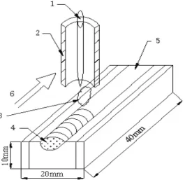
GTA cladding was carried out on a MW3000 Digital Tungsten Inert Gas welding machine which is presented in Fig. 1. A tungsten electrode of 2.0mm diameter was used to produce a stable arc. The GTA cladding parameters were: Current=120A, Voltage=14V, Argon flow rate= 9L/min, and Welding speed=5mm/s.Files should be in MS
Word format only and should be formatted for direct printing. Figures and tables should be embedded and not supplied separately. Please make sure that you use as much as possible normal fonts in your documents. Special fonts, such as fonts used in the Far East (Japanese, Chinese, Korean, etc.) may cause problems during processing. To avoid unnecessary errors you are strongly advised to use the ‘spellchecker’ function of MS Word. Follow this order when typing manuscripts: Title, Authors, Affiliations, Abstract, Keywords, Main text (including figures and tables), Acknowledgements, References, Appendix. Collate acknowledgements in a separate section at the end of the article and do not include them on the title page, as a footnote to the title or otherwise.
Fig. 1. Schematic representation of the GTA cladding (1. electrode; 2. injecting nozzle; 3. shielding gas (Ar); 4. fusion zone; 5. cladding materials; 6.welding direction)
1.3. Coatings characterization
The crystallization phases of the coating was analyzed by X-ray powder diffraction (XRD, D/MAX2200), using CuKSgenerated at 40kV and 30mA as the radiation source, the scanning rate was 2º/min and the scanning angles ranged from 10º to 90º.The microstructure, composition and particulates distributions morphology study of coating samples, after wear tests, were conducted by scanning electron microscopy (SEM, MX-2600FE).
1.4. Construction of references
The microhardness of coating along the depth of the cross-section was measured by a MHV2000 microhardness tester. A MMS-2A type friction and wear tester was used to measure the wear resistance of the specimens. The wear experiments without lubrication were done normal atmosphere conditions and at the room temperature. The sample was machined to block with the size of 20mm×5mm×5mm. A GCr15 steel with the hardness of HRC60 was used as the friction counterpart. The wear conditions were a normal load of 200N, a sliding speed of 200r/min. The wear volume was calculated using the following formula[17]:V=Bb3/12r(mm3), whereBis the width of the sample (mm), bis the width of the wear trail (mm) andris the outer radius of the wear ring (mm).
3. Results
1.5. XRD analysis
The XRD pattern of the cladding layer is shown in Fig. 2. The diffraction results were compared with the results published by the Joint Committee on Powder Diffraction Standards (JCPDS). After the Gas Tungsten Arc (GTA) cladding, it was noted that there wereU-Ni, TiB2, TiN, (Fe,Cr)23C6 and Cr2B in the coating. This phase constituent
was beneficial to increase the micro-hardness and wear resistance of the coating. Moreover, this phase constituent indicated that TiB2 and TiN can be synthesized in situ by the reaction between Ti and BN during the Gas Tungsten Arc (GTA) cladding process. The reactions occur as follows[10]:
(1)
According to Eq. (1), when the Ti/BN=3/2(i.e., x=0), a stoichiometric nitride phase TiN could be obtained. For Ti/BN <3/2, TiB intermediate phase and residual Ti are detected, and for Ti/BN >3/2, BN might react with TiN to produce TiB2and N2[18].
According to thermodynamic data for the Ti/BN=3/2 reaction reported in the literature[18], the enthalpy of reaction (1) at standard condition is H0298=452kJ/mol and the free enthalpy isG0=-383 kJ/mol at 1800. It can be seen that the reactions are exothermic and highly favorable.
1.6. SEM analysis
A cross-sectional view of the Gas Tungsten Arc (GTA) cladding is shown in Fig. 3. From the cross-sectional view, the coating was defect-free, without any pores and cracks. It can be found that there is a white band between the coating and the substrate, it is indicated that there is a metallurgical combination between the coating and the substrate.
Fig.2. X-ray diffraction diagrams of the GTA composite coatings
Fig.3. Micrograph showing cross-section morphology of the GTA composite coating
The coating could be divided into three regions, the cladding zone (CZ), transition zone (TZ) and heat affected zone (HAZ).The formed particulates mostly centralize in CZ, less ones in TZ and HAZ is in the substrate. We
20 40 60 80 100 0 200 400 600 800 -Ni TiB2 TiN (Fe,Cr)23C6 Cr2B Intensity (a .u ) 2Theta(degree) coating substrate Interface 200m x TiN TiB x BN x Ti x 1 2 2 1 ) 1 ( 2 3
separate CZ into three parts owing to the different distribution of particulates in the composite coating. SEM micrographs of the GTA coating were shown in Fig. 4. Figures 4a, b and c exhibit the particulate distribution in the top part, middle and bottom of the TZ, respectively. A lot of rectangular or hexagonal prism shapes phases are homogenously distributed in the top of composite coating, the appearances of which are TiB2 particulates due to its hexagonal crystal structure. (Fig.4a) Generally, in the molten pool the liquid temperature gradient decreases rapidly from the maximum to the minimum, while the solidification rate increases from the minimum to the maximum from the molten pool bottom to its top. The density of TiB2 (4.25 g/cm-3) and TiN (5.43 g/cm-3) are much lower than nickelbased alloy. In GTA processing, the in situ formed TiB2 particles will interact with advancing solid-liquid interface and TiB2 particles will float upward in the molten pool. With the distance from top surface increasing, the amount of near-spherical shaped TiN particulates augments remarkably in the middle. There are only less TiN particulates and carbide till the bottom of the coating in TZ.
Fig.4 SEM micrographs of coating in coating zone (CZ) (a) the top part; (b) the middle one; (c)the bottom one
1.7. Micro-hardness and wear
The micro-hardness of sample as a function of the distance from the top of TiB2-TiN particulates reinforced Ni-based surface composite coating was measured as shown in Fig.5. From Fig.5, it can be found that the micro-hardness of the composite coating gradually decrease with the distance leaving the surface coating. Also, it was found that the micro-hardness of the coating zone was in the range of 1100-1380 HV0.2, which was ~5-7 times higher than of the 16Mn steel substrate. It can be concluded that presence of TiB2 and TiN particulates has a significant improvement in the hardness of the composite coating. The transition zone is harder than substrate due to alloy elements (such as Ni, Cr) were engulfed during the solidification causing the solution strengthening .
TiB2 a 20m b TiN 20m c (Fe,Cr)23C6 20m %-Ni
Fig.5. Microhardness distribution within the coating
Fig.6 shows the wear volume of composite coatings and 16Mn steel substrate. It is clear that wear volume of coatings is smaller than that of 16Mn steel. This is reason that due to there are many in situ TiB2 and TiN particulates , which are dispersively distributed in the coating, resulting in dispersion strengthening, and GTAC has rapid cooling rate, arousing cryptomere strengthening.
Fig.6. Wear volume of the composite coating and 16Mn steel substrate
The typical worn surface morphologies of the 16Mn steel base and the composites coating are shown in Fig. 7. As can be seen, there are a lot of deep and wide grooves on the worn surface of the 16Mn steel matrix, as the hard inclusion in GCr15 steel plough across the relatively softer substrate, remove and push the material to the sides caused the obvious scratch grooves on the worn surface. The 16Mn steel matrix will began to its hardness due to the frictional heat caused extremely high local temperature. Simultaneously, it caused adhesion of the matrix materials to the slip ring surface. (Fig.7a). However, the worn surface of the composites coating was relatively smooth showing some signs of slight peeling and shallow scratch groove, attributed to mild abrasive wear at room temperature (Fig. 7b). As can be seen, there is no severe pullout or adhesion of the particulates from the surface was observed and this shows that strong interface bonding and good compatibility between the in situ synthesized particulates and the 16Mn steel matrix. This is due to the TiB2 and TiN greatly increased the strength and hardness of the coating so it could retard the defects from being formed in the subsurface strong interfacial bond, and compared with the formation of pure TiB2, the TiN can further improvement stability at high temperature. As a result, the GTA coating shows exceptional wear resistance.
0.0 0.5 1.0 1.5 2.0 0 200 400 600 800 1000 1200 1400 1600 TZ HAZ
Distance from surface of the coating/mm
Mi cr ohar dnes s/ H V 0. 2 Substrate Coating 10 20 30 40 50 60 0 5 10 15 20 25 30 35 40 45 We ar v ol um e ( m m 3)
Wear time (min) 16Mn steel substrate composite coating
Fig.7 SEM micrographs of worn surfaces of 16Mn steel substrate(a) and GTA composite coating(b) samples under load of 200N and speed of 200 rpm.
4. Conclusion
GTA cladding technique has been successfully used to synthesis of TiB2-TiN reinforced Ni matrix composite in using titanium and titanium nitride (Ti/BN=0.67) and Ni powders (70%) as the raw materials. The microstructure of the coating is mainly composed of U-Ni, TiB2, TiN, (Fe,Cr)23C6 and Cr2B. The gained TiB2 in the composite exhibits rectangular or hexagonal prism shapes, while TiN gives the shape of near-spherical. The cladding zone of composite coating consist of three distinct regions: the TiB2 distribution in the top zone, the TiN in the middle zone and the transition zone. The highest micro-hardness is about 1400HV and six times as high as the substrate. Wear test shows that the wear resistance of the coating is much higher than 16Mn steel substrate. The main wearing mechanisms of the GTA cladding coating is micro-cutting.
Acknowledgements
This research is supported by Scientific Research Fund of Heilongjiang Provincial Education Department (No.11551419) and Key Project of and Technology Department of Heilongjiang Province of China. (No.12511469).
References
[1] Van der Geer J, Hanraads JAJ, Lupton RA. The art of writing a scientific article.J Sci Commun2000;163:51–9.
[2] Strunk Jr W, White EB.The elements of style. 3rd ed. New York: Macmillan; 1979.
[3] Mettam GR, Adams LB. How to prepare an electronic version of your article. In: Jones BS, Smith RZ, editors.Introduction to the
electronic age, New York: E-Publishing Inc; 1999, p. 281–304
[1] T jong S C, Ma Z Y. Microst ructural and mechanical characteristics of in situ metal matrix composites.Mater Sci Eng A, 2000, 29:
49-113.
[2] Z. Sadeghian, M. H. Enayati, P. Beiss. Characterisation of in situ Al-TiB2nanocomposite powder synthesised by mechanical alloying.
Power Metallurgy, 2011, 54: 46-49
[3] Akhtar Farid, S. J. Guo, F. E. Cui, P. Z. Feng, Lin T. TiB2and TiC stainless steel matrix composites.Mater Lett, 2007, 61: 189.
[4] Kumar S, Chakraborty M, Sarma V.S, Murty B.S. Tensile and wear behaviour of in situ Al-7Si/TiB2 particulate composites.Wear,
2008,265: 134.
[5] B. H. Li, Y. Liu, L. He, H. Cao, S. Gao, J. Li. Fabrication of in situ TiB2reinforced steel matrix composite by vacuum induction melting
and its microstructure and tensile properties.INT J CAST METAL RES, 2010, 23: 211-215.
[6] A Kulpa, T. Troczynski, J. Am. Ceram. Soc.. 79 (1996) 518-606. [7] J. Ramberg, C. Wolfe, W. Williams, J. Am. Ceram. Soc.. 68 (1985) 78-84.
100m a
100m b
[8] R. Tomoshige, A. Murayama, T. Masushita, J. Am. Ceram. Soc..80 (1997) 761.
[9] K. Wang, V. D. Krstic. Reaction sintering of TiN-TiB2 ceramics.Acta Mater, 2003; 51:1809.
[10] L. Zhan, P. Shen, C. J. Chuan. Effect of BN/Ti ratio on the reaction synthesis of TiB2-TiNx ceramics.INT J MOD PHYS B., 2009, 23:
1172-1178.
[11] Rie K T, Pfohl C., Lee S.H., Kang C.S. Development of zirconium and boron containing coatings for the application on aluminium diecasting tools by means of MO-PACVD. Surf Coat Technol, 1997, 97: 425- 436.
[12] Rother B, Kappl H , Pfeifer- Schaller I, Ebersbach, G., Jehn, H. A.. Property distribution on three-dimensionally shaped PVD-coated
samples.Surf Coat Technol, 1997, 97: 200-205.
[13] B. S. Du, Z. D. ZOU, X. H. Wang, Q. M. Li. In situ synthesis of TiC-TiB2 reinforced FeCrSiB composite coating by laser cladding. Surface Review & Letters, 2007, 14: 315-319.
[14] Lepakova, O. K., Raskolenko, L. G., Yu. M. Maksimov.. Self-propagating high-temperature synthesis of composite material TiB2-Fe.J
Mater Sci., 2004, 393: 3723-3732.
[15] X.H. Wang, S.L. Song, Z.D. Zou, S.Y. Qu. Fabricating TiC particles reinforced Fe-based composite coatings produced by GTAW
multi-layers melting process.Mater. Sci. Eng. A, 2006, 441: 60-67.
[16] Soner Buytoz, Mustafa Ulutan. In situ synthesis of SiC reinforced MMC surface on AISI 304 stainless steel by TIG surface alloying. Surf.Coat.Technol, 2006, 200: 3698-3704.
[17] X. H. Wang, Z. D. Zou, S. L. Song, S. Y. Qu. Microstructure and wear properties of in situ TiC/FeCrBSi composite coating prepared by
gas tungsten arc welding.Wear, 2006, 260: 705-710.
[18] G. J. Zhang, M. Ando, J. F. Yang, T. Ohji, S. Kanzaki. Boron carbide and nitride as reactants for in situ synthesis of boride-containing ceramic composites. J Eur. Ceram. Soc., 2004, 24: 171-178.